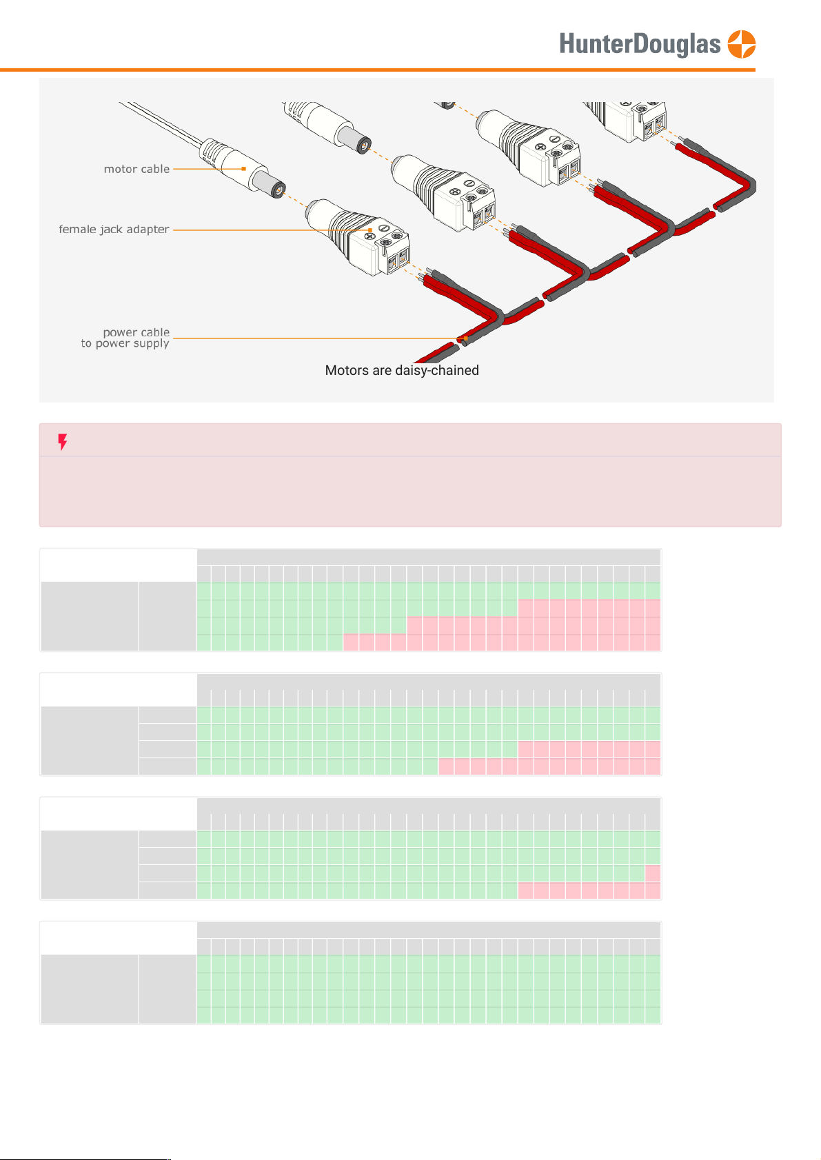
Motors are daisy-chained
Depending on the motor count per chain and used wire surface/diameter,
a maximum cable length per chain is allowed
See table below for more information.
wire area: 0.5mm² wire length [m.]
1 2 3 4 5 6 7 8 9 101112131415161718192021222324252627282930
# motors 1 0.1 0.1 0.2 0.3 0.4 0.4 0.5 0.6 0.6 0.7 0.8 0.8 0.9 1 1.1 1.1 1.2 1.3 1.3 1.4 1.5 1.5 1.6 1.7 1.8 1.8 1.9 2 2 2.1
20.1 0.3 0.4 0.6 0.7 0.8 1 1.1 1.3 1.4 1.5 1.7 1.8 2 2.1 2.2 2.4 2.5 2.7 2.8 2.9 3.1 3.2 3.4 3.5 3.6 3.8 3.9 4.1 4.2
30.2 0.4 0.6 0.8 1.1 1.3 1.5 1.7 1.9 2.1 2.3 2.5 2.7 2.9 3.2 3.4 3.6 3.8 4 4.2 4.4 4.6 4.8 5 5.3 5.5 5.7 5.9 6.1 6.3
40.3 0.6 0.8 1.1 1.4 1.7 2 2.2 2.5 2.8 3.1 3.4 3.6 3.9 4.2 4.5 4.8 5 5.3 5.6 5.9 6.2 6.4 6.7 7 7.3 7.6 7.8 8.1 8.4
wire area: 0.75mm² wire length [m.]
1 2 3 4 5 6 7 8 9 101112131415161718192021222324252627282930
# motors 1 0 0.1 0.1 0.2 0.2 0.3 0.3 0.4 0.4 0.5 0.5 0.6 0.6 0.7 0.7 0.7 0.8 0.8 0.9 0.9 1 1 1.1 1.1 1.2 1.2 1.3 1.3 1.4 1.4
20.1 0.2 0.3 0.4 0.5 0.6 0.7 0.7 0.8 0.9 1 1.1 1.2 1.3 1.4 1.5 1.6 1.7 1.8 1.9 2 2.1 2.1 2.2 2.3 2.4 2.5 2.6 2.7 2.8
30.1 0.3 0.4 0.6 0.7 0.8 1 1.1 1.3 1.4 1.5 1.7 1.8 2 2.1 2.2 2.4 2.5 2.7 2.8 2.9 3.1 3.2 3.4 3.5 3.6 3.8 3.9 4.1 4.2
40.2 0.4 0.6 0.7 0.9 1.1 1.3 1.5 1.7 1.9 2.1 2.2 2.4 2.6 2.8 3 3.2 3.4 3.5 3.7 3.9 4.1 4.3 4.5 4.7 4.9 5 5.2 5.4 5.6
wire area: 1.0mm² wire length [m.]
1 2 3 4 5 6 7 8 9 101112131415161718192021222324252627282930
# motors 1 0 0.1 0.1 0.1 0.2 0.2 0.2 0.3 0.3 0.4 0.4 0.4 0.5 0.5 0.5 0.6 0.6 0.6 0.7 0.7 0.7 0.8 0.8 0.8 0.9 0.9 0.9 1 1 1.1
20.1 0.1 0.2 0.3 0.4 0.4 0.5 0.6 0.6 0.7 0.8 0.8 0.9 1 1.1 1.1 1.2 1.3 1.3 1.4 1.5 1.5 1.6 1.7 1.8 1.8 1.9 2 2 2.1
30.1 0.2 0.3 0.4 0.5 0.6 0.7 0.8 0.9 1.1 1.2 1.3 1.4 1.5 1.6 1.7 1.8 1.9 2 2.1 2.2 2.3 2.4 2.5 2.6 2.7 2.8 2.9 3 3.2
40.1 0.3 0.4 0.6 0.7 0.8 1 1.1 1.3 1.4 1.5 1.7 1.8 2 2.1 2.2 2.4 2.5 2.7 2.8 2.9 3.1 3.2 3.4 3.5 3.6 3.8 3.9 4.1 4.2
wire area: 1.5mm² wire length [m.]
1 2 3 4 5 6 7 8 9 101112131415161718192021222324252627282930
# motors 1 0 0 0.1 0.1 0.1 0.1 0.2 0.2 0.2 0.2 0.3 0.3 0.3 0.3 0.4 0.4 0.4 0.4 0.4 0.5 0.5 0.5 0.5 0.6 0.6 0.6 0.6 0.7 0.7 0.7
20 0.1 0.1 0.2 0.2 0.3 0.3 0.4 0.4 0.5 0.5 0.6 0.6 0.7 0.7 0.7 0.8 0.8 0.9 0.9 1 1 1.1 1.1 1.2 1.2 1.3 1.3 1.4 1.4
30.1 0.1 0.2 0.3 0.4 0.4 0.5 0.6 0.6 0.7 0.8 0.8 0.9 1 1.1 1.1 1.2 1.3 1.3 1.4 1.5 1.5 1.6 1.7 1.8 1.8 1.9 2 2 2.1
40.1 0.2 0.3 0.4 0.5 0.6 0.7 0.7 0.8 0.9 1 1.1 1.2 1.3 1.4 1.5 1.6 1.7 1.8 1.9 2 2.1 2.1 2.2 2.3 2.4 2.5 2.6 2.7 2.8
MANUAL
Page 7 of 13 version: 1.0