Huntleigh IRT10 User manual

Wireless Tympanic
Thermometer
IRT10

3
Table of Contents
Contents
1. General Safety Information................................................5
1.1 Warnings / Cautions ............................................................................................. 5
2. Introduction ........................................................................6
2.1 Features of the IRT10 Wireless Themometer................................................ 6
2.2 Intended Use.................................................................................................. 7
2.2 Contraindications ........................................................................................... 7
2.4 About This Manual ......................................................................................... 7
3. Description of Controls, Indicators, Symbols and
Displays ..............................................................................8
3.5 Thermometer Controls and Display .............................................................. 8
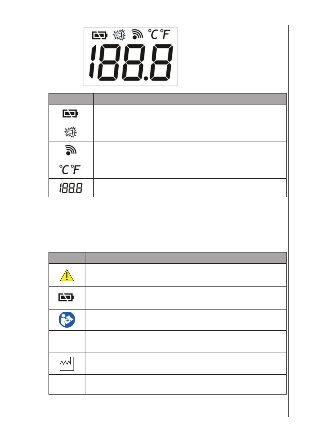
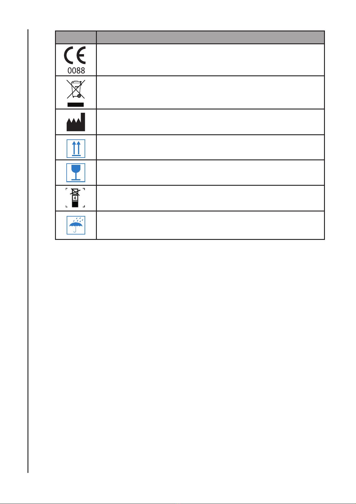
3.2 Description of Symbols / Indicators................................................................ 9
4. Setup...................................................................................11
4.1 Unpacking and Inspection.............................................................................. 11
4.2 List of Components ........................................................................................ 11
4.3 Connecting the Thermometer to the host ...................................................... 11
4.4 Installing the Batteries.................................................................................... 12
4.5 Pairing the Thermometer and Main Unit ........................................................ 12
5. Using the Thermometer .....................................................13
5.1 Temperature Measurement............................................................................ 13
6. Care & Cleaning..................................................................15
6.1 General .......................................................................................................... 15
6.2 Returning the IRT10 Thermometer and System Components....................... 15
6.3 Service ........................................................................................................... 15
6.4 Periodic Safety Checks.................................................................................. 15
7. Troubleshooting..................................................................16
7.1 General .......................................................................................................... 16
7.2 Obtaining Technical Assistance ..................................................................... 16
8. Electromagnetic Compatibility ..........................................17
9. Specifications .....................................................................21
9.1 Equipment Classification ............................................................................... 21
9.2 Standards....................................................................................................... 21
9.3 General .......................................................................................................... 21
9.4 Environmental ................................................................................................ 22
9.5 Measurement Parameters ............................................................................. 22
10. Warranty & Service ..........................................................23
10.1 Service Returns ............................................................................................. 23

4
Table of Contents
Notice
This document contains proprietary information that is protected by copyright. All Rights
Reserved. Reproduction, adaptation, or translation without prior written permission is prohibited,
except as allowed under the copyright laws.
Warranty
The information contained in this document is subject to change without notice.
Huntleigh Healthcare Ltd makes no warranty of any kind with regard to this material, including,
but not limited to, the implied warranties or merchantability and fitness for a particular purpose.
Huntleigh Healthcare Ltd shall not be liable for errors contained herein or for incidental or
consequential damages in connection with the furnishing, performance, or use of this material.
Revision History
The documentation part number and revision number indicate its current edition. The revision
number changes when a new edition is printed in accordance with the revision history of the
documentation. Minor corrections and updates which are incorporated at reprint do not cause
the revision number to change. The document part number changes when extensive technical
changes are incorporated.
© Huntleigh Healthcare Ltd
All rights reserved
The IRT10 is in conformity with the Medical Devices Directive 93/42/EEC as
amended by 2007/47/EC and has been subject to the conformity assurance
procedures laid down by the Council Directive.
Manufactured in the UK by Huntleigh Healthcare Ltd.
As part of the ongoing development programme the company reserves the right
to modify specifications and materials without notice.
Smartsigns®and Huntleigh are registered trademarks of Huntleigh Technology
Ltd.
© Huntleigh Healthcare Ltd. 2017

5
1. General Safety Information
This section contains important safety information related to general use of the IRT10
wireless thermometer. Other important safety information appears throughout the manual
Important! Before using this equipment, please study this manual carefully and
familiarise yourself with the controls, display features and operating techniques.
Ensure each user fully understands the safety and operation of the unit, as
misuse may cause damage to the unit or injury to the user or patient.
1.1 Warnings / Cautions
General warning / caution Refer to Instructions for Use
WARNING: Check the equipment prior to use and ensure its safe and
proper use.
WARNING: Before use, carefully read directions for use, including all
warnings, cautions, and instructions.
WARNING: If the battery shows any signs of damage, leakage, or
cracking, it must be replaced immediately, by a qualified service person,
and only with a battery approved by the manufacturer.
WARNING: The monitor is intended only as an adjunct in patient
assessment. It must be used in conjunction with clinical signs and
symptoms.
WARNING: It is possible that any radio frequency transmitting
equipment and other sources of electrical noise such as cellular
phones, due to close proximity or strength of a source, may result in
disruption of performance.
CAUTION: U.S. Federal law restricts this device to sale by or on the
order of a licensed healthcare practitioner.
General Safety Information

6
2. Introduction
WARNING: The Wireless Tympanic Thermometer is intended only as an
adjunct in patient assessment. It must be used in conjunction with clinical
signs and symptoms.
This manual contains information about the Wireless Tympanic Thermometer (Order
code: IRT10).
It is available as an option for the SC300 SPOT CHECK Vital Signs Monitor.
2.1 Features of the IRT10 Wireless Themometer
Physical
The IRT10 wireless tympanic thermometer is a clinical grade hand held thermometer
indicated for the intermittent measurment of body temperature in patients of all ages.
Electrical
The Thermometer is powered by two AAA dry cells.
Display
The Thermometer presents the following information on the integrated display:
• Battery status
• Lens cover indicator
• Wireless pairing status
• Temperature measurment
• Measurement scale °C or °F
General Safety Information

7
2.2 Intended Use
The Thermometer is intended for use by trained healthcare professionals in healthcare
settings to measure human body temperature in patients of all ages.
It uses an infra red technique to measure the amount of infrared energy reflected from the
tympanic membrane.
2.2 Contraindications
The Thermometer should not be used if the following situations are present:
Do not use the thermometer if there is any blood or drainage in the ear canal.
Do not use the thermometer if the patient presents with inflamatory condition of the ear
canal.
Do not use the thermometer if the ear canal is blocked with cerumen.
Do not use the thermometer if ear drops or medication has been applied to the ear
2.4 About This Manual
Read the entire manual including the Safety Information section, before you operate the
monitor.
General Safety Information

8
3. Description of Controls, Indicators,
Symbols and Displays
3.5 Thermometer Controls and Display
1
2
3
4
5
6
1 Temperature probe status indicator
2 Start measurment
3 Display
4 Infra red sensor
5 Lens ejector
6 Battery compartment
Introduction

9
Key Function / Display
Battery status
Lens filter status
Wireless status
Scale ºC or ºF
Measurement
3.2 Description of Symbols/ Indicators
The symbols and Indicators are described as follows:
Symbols Description
Attention, consult accompanying documents.
Battery charging indicator lamp
Refer to instructions for use
IPX1 Protection against vertically falling water drops
Date of manufacture
SN Serial number
Introduction

10
Symbols Description
Conformité Européenne Complies with medical device directive 93/42/
EEC
Disposal instructions
Manufacturer
This way Up
Fragile – Handle with care
Limit of stacking layers
Keep dry
Description of Controls, Indicators, Symbols and Displays

11
4. Setup
WARNING: The IRT10 Wireless Thermometer is a prescription device and is
to be operated by qualified personnel only. It is designed for use by medical
clinicians.
WARNING: Discarded battery may explode during incineration. Follow local
government ordinances and recycle instructions regarding disposal or recycling
of device components, including batteries. Do not dispose of batteries in refuse
containers.
4.1 Unpacking and Inspection
The Thermometer is shipped in one carton. Examine the carton carefully for evidence
of damage. Contact Huntleigh Healthcare Ltd Service Department immediately if any
damage is discovered. Return all packing material and Thermometer. Refer to the
Maintenance section for instructions on returning damaged items.
4.2 List of Components
Quantity Item Quantity Item
1 Thermometer 1 Lens covers
2 AAA dry cells 1 Cradle
4.3 Connecting the Thermometer to the host
To facilite ease of use, the Thermometer can be fitted to the SC300 using the cradle
supplied.
Description of Controls, Indicators, Symbols and Displays

12
4.4 Installing the Batteries
WARNING: Dispose of Battery in accordance with local requirements and
regulation. Follow local instructions regarding disposal or recycling of
batteries.
CAUTION: Measured or displayed data may not be assured in the low
battery or the critical low battery condition.
CAUTION: Discarded battery may explode during incineration. Recycle
used batteries properly. Do not dispose of batteries in refuse containers.
Remove the battery cover to expose
the battery compartment
Place new batteries into compartment
paying attention to the polarity, close the
compartment ensuring it snaps into place.
The system is ready for use
4.5 Pairing the Thermometer and Main Unit
1. Make sure the main unit and ear thermometer are both switched OFF.
2. Press and hold the “ejector key” on the thermometer and switch it ON.
3. The thermometer display will alternate between ºC and ºF and then display “SE”.
4. When “SE” is displayed, release the ejector button and switch the main unit ON.
5. Pairing will be established when the icon is displayed on the host unit.
6. If pariring has failed, no icon will be displayed.
Description of Controls, Indicators, Symbols and Displays

13
5. Using the Thermometer
The Thermometer must be calibrated at least once every two years, contact your
service personnel when calibration is necessary
Use only specified protective lens covers
The protective lens cover is single-use. Repeated use might give rise to cross
infection.
The protective lens cover must be used when measuring, if not, it might cause
cross infection or inaccurate readings.
Before use, check whether the cover is free from damage, if not, don’t use.
Handle the thermometer with care, it should be stored in the cradle when not in
use.
Discard the protective lens cover in accordance with the local regulations.
During the monitoring process, the temperature measuring instrument will
automatically check itself once per hour. Self-checking will last 2 seconds, and
will not affect the normal working of the temperature monitor.
Measurments are sent via a wireless connection established between the thermometer
and the main unit.
Both items (Thermometer and unit) must be paired to enable data transfer.
5.1 Temperature Measurement
1. Install a new protective lens cover to the thermometer.
2. When correctly fitted, the icon changes to .
3. Position the patient with their head moved to one side, gently pull the ear backward
to straighten the ear canal. Gently place the sensor into the ear canal.
Description of Controls, Indicators, Symbols and Displays

14
4. Press the START button once, the sensor will sound a quick double beep indicating
that its ready to measure.
Press the START button once again and after a short period, the sensor will sound a
long single tone indicating that the measurement is complete.
5. Remove the thermometer.
6. The measurement will be shown on the thermometer’s screen, it will be automatically
transferred to the monitor.
Thermometer display
Monitor display
7. Press the eject key to remove the disposable lens cover.
8. Place the lens cover in the appropriate waste collection point and place the
thermometer onto the unit
Description of Controls, Indicators, Symbols and Displays

15
6. Care & Cleaning
6.1 General
The probe tip is the most delicate part of the thermometer. It has to be clean and intact to
ensure accurate readings.
Gently wipe the surface of the probe tip with a cotton swab or soft cloth moistened with
alcohol.
After the alcohol has completely dried, fit a new lens filter and take a temperature
measurement.
If the probe tip is damaged, please contact your service agent.
Use a soft, dry cloth to clean the thermometer display and exterior.
Do not use abrasive cleaners.
Never submerge the thermometer in water or any other liquid.
Store thermometer and lens filters in a dry location free from dust and contamination and
away from direct sunlight.
6.2 Returning the IRT10 Thermometer and
System Components
Contact Huntleigh Healthcare Ltd Service Department for shipping instructions. Pack the
accessory items in its original shipping carton. If the original carton is not available, use
a suitable carton with appropriate packing material to protect the device during shipping.
Return by any shipping method that provides proof of delivery.
6.3 Service
Apart from a 2 year calibration check, the Wireless Thermometer requires no routine
service other than cleaning or battery maintenance that is mandated by the user’s
institution. For more information, refer to Smartsigns®Compact 300 service manual.
Qualified service personnel in the user’s institution should perform periodic inspections
of the equipment. If service is necessary, contact qualified service personnel or Huntleigh
Healthcare Ltd Service Department.
If the institution’s service personnel cannot correct problems, the equipment should be
returned to Huntleigh Healthcare Ltd for service. Contact Huntleigh Healthcare Ltd Service
Department for return instructions.
6.4 Periodic Safety Checks
It is recommended that the following checks be performed every 24 months.
• Inspect the equipment for mechanical and functional damage.
• Inspect the safety relevant labels for legibility.
Setting up the Monitor

16
7. Troubleshooting
WARNING: If you are uncertain about the accuracy of any measurement,
check the patient’s vital signs by alternate means; then make sure the
monitor is functioning correctly.
WARNING: Only qualified service personnel should remove the cover.
There are no user-serviceable parts inside.
7.1 General
If the equipment is unable to perform any of its monitoring functions because of the loss of
software control or a detected hardware malfunction, an error code is presented.
In the unlikely event of the unit developing a fault, fault codes will be shown in the
corresponding area and the related parameters will flash on the screen
Description Cause Solution
Low power Low power Replace batteries
Blank Screen
Auto shutdown Restart the device
Battery installation incorrectly Check the correct installation of the
batteries
Low power Replace batteries
The screen is still blank Contact service personnel
Er1
The environment temperature
is out of range 10~40°C (33.8-
39.2°F)
Move the device to appropriate
environment and wait 30 minutes prior
to taking a temperature.
Er2 The environment temperature
is not stable
Do not take measurement until the
environment temperature is stable
Er3 Infrared module failure Contact service personnel
Hi The measurement is out of
range > 42.2°C (108°F)
Make sure the operation method is
correct and the lens filter is new and
clean. Remeasure.
Lo The meaurment is out of range
<34°C (108°F)
Make sure the operation method is
correct and the lens filter is new and
clean. Remeasure.
7.2 Obtaining Technical Assistance
For technical information and assistance, or to order a service manual, call Huntleigh
Healthcare Ltd Service Department. The service manual includes information required by
qualified service personnel when servicing the Smartsigns®Compact 300.
When calling the Huntleigh Healthcare Ltd Service Department, you may be asked to
tell the representative the software version number of your equipment. Qualified service
personnel or Huntleigh Healthcare Ltd Service Department may help you check the
software version installed in your equipment.
Setting up the Monitor

17
8. Electromagnetic Compatibility
Make sure the environment in which the equipment is installed is not subject to strong
sources of electromagnetic interference (e.g. radio transmitters, mobile phones).
This equipment generates and uses radio frequency energy. If not installed and used
properly, in strict accordance with the manufacturer’s instructions, it may cause or be
subject to interference. Type-tested in a fully configured system, complies with EN60601-
1-2, the standard intended to provide reasonable protection against such interference.
Whether the equipment causes interference may be determined by turning the equipment
off and on. If it does cause or is affected by interference, one or more of the following
measures may correct the interference:
• Reorienting the equipment
• Relocating the equipment with respect to the source of interference
• Moving the equipment away from the device with which it is interfering
• Plugging the equipment into a different outlet so that the devices are
on different branch circuits
WARNING: The use of accessories, transducers and cables other than
those specified, with the exception of transducers and cables sold by the
manufacturer of the Smartsigns® Compact 300 as replacement parts for
internal components, may result in increased emissions or decreased
immunity of the Smartsigns® Compact 300.
WARNING: The Smartsigns® Compact 300 should not be used adjacent
to or stacked with other equipment and that if adjacent or stacked use is
necessary, the Smartsigns® Compact 300 should be observed to verify
normal operation in the configuration in which it will be used
WARNING: Portable RF communications equipment (including peripherals
such as antenna cables and external antennas) should be used no closer
than 30 cm (12 inches) to any part of the Smartsigns® Compact 300
including cables specified by the manufacturer. Otherwise, degradation of
the performance of this equipment could result.
Guidance and Manufacturer’s declaration - electromagnetic emissions
The IRT10 infrared ear thermometer is intended for use in the electromagnetic environment
specified below. The customer or the user of the IRT10 infrared ear thermometer should assure that
it is used in such an environment.
Emissions Test Compliance Electromagnetic Environment - guidance
RF emissions
CISPR 11 Group 1
The IRT10 infrared ear thermometer uses RF energy only
for its internal function. Therefore, its RF emissions are
very low and are not likely to cause any interference in
nearby electronic equipment.
RF emissions
CISPR 11 Class A
The IRT10 infrared ear thermometer is suitable for use in
all establishments, other than domestic and those directly
connected to the public low-voltage power supply network
that supplies buildings used for domestic purposes.
Harmonic emissions
IEC 61000-3-2 Class A
Voltage fluctuations /
flicker emissions
IEC 61000-3-3
Complies
Setting up the Monitor

18
Guidance and Manufacturer’s declaration - electromagnetic immunity
The IRT10 infrared ear thermometer is intended for use in the electromagnetic environment specified below.
The customer or the user of the IRT10 infrared ear thermometer should assure that it is used in such an
environment.
Immunity
Test IEC 60601 test level Compliance
level Electromagnetic Environment - guidance
Portable and mobile RF communications equipment
should be used no closer to any part of the
Smartsigns® Compact 300, including cables, than
the recommended separation distance calculated
from the equation applicable to the frequency of the
transmitter.
Conducted RF
IEC 61000-4-6
3 Vrms
150kHz to 80MHz
outside ISM bandsa
6 Vrms
150 kHz to 80 MHz
in ISM and amateur
radio bands
3V d= 1.2 √P
Radiated RF
IEC 61000-4-3
3 V/m
80MHz to 2.5GHz 3V/m
d= 1.2 √P80MHz to 800MHz
d= 2.3 √P800MHz to 2.5GHz
where Pis the maximum output power rating of the
transmitter in watts (W) according to the transmitter
manufacturer and dis the recommended separation
distance in metres (m). b
Field strengths from fixed RF transmitters, as
determined by an electromagnetic site survey, c
should be less than the compliance level in each
frequency range d.
Interference may occur in the vicinity of the
equipment marked with the following symbol:
NOTE 1 At 80MHz and 800MHz, the higher frequency range applies.
NOTE 2 These guidelines may not apply in all situations. Electromagnetic propagation is affected by
absorption and reflection from structures, objects and people.
aThe ISM (industrial, scientific and medical) bands between 150 kHz and 80 MHz are 6,765 MHz, to 6,795
MHz; 13,553 MHz to 13,567 MHz; 26,957 MHz to 27,283 MHz; and 40,66 MHz to 40,70 MHz.
bThe compliance levels in the ISM frequency bands between 150 kHz and 80 MHz and in the frequency
range 80 MHz to 2,5 GHz are intended to decrease the likelihood that mobile/portable communications
equipment could cause interference if it is inadvertently brought into patient areas. For this reason, an
additional factor of 10/3 is used in calculating the recommended separation distance for transmitters in these
frequency ranges.
cField strengths from fixed transmitters, such as base stations for radio (cellular/cordless) telephones
and land mobile radios, amateur radio, AM and FM radio broadcast and TV broadcast cannot be predicted
theoretically with accuracy. To assess the electromagnetic environment due to fixed RF transmitters, an
electromagnetic site survey should be considered. If the measured field strength in the location in which
the IRT10 infrared ear thermometer is used exceeds the applicable RF compliance level above, the
IRT10 infrared ear thermometer should be observed to verify normal operation. If abnormal performance
is observed, additional measures may be necessary, such as re-orienting or relocating the Smartsigns®
Compact 300.
dOver the frequency range 150kHz to 80kHz, field strengths should be less than 3V/m.
Setting up the Monitor

19
Guidance and Manufacturer’s declaration - electromagnetic immunity
The IRT10 infrared ear thermometer intended for use in the electromagnetic environment specified below.
The customer or the user of the IRT10 infrared ear thermometer should assure that it is used in such an
environment.
Immunity Test IEC 60601 test
level
Compliance
level
Electromagnetic Environment -
guidance
Electrostatic
discharge (ESD)
IEC 61000-4-2
± 6 kV contact
± 8 kV air
± 6 kV contact
± 8 kV air
Floors should be wood, concrete or
ceramic tile. If floors are covered with
synthetic material, the relative humidity
should be at least 30%.
Electrical fast
transient burst
IEC 61000-4-4
± 2 kV for power
supply lines
± 1 kV for input/
output lines
± 2 kV for power
supply lines
± 1 kV for input/
output lines
Mains power quality should be that of a
typical commercial or hospital environment.
Surge
IEC 61000-4-5
± 1 kV line(s) to
line(s)
± 2 kV line(s) to
earth
± 1 kV line(s) to
line(s)
± 2 kV line(s) to
earth
Mains power quality should be that of a
typical commercial or hospital environment.
Voltage dips, short
interruptions and
voltage variations on
power supply input
lines
IEC 61000-4-11
<5 % Ur
(>95 % dip in Ur )
for 0,5 cycles
40 % Ur
(60 % dip in Ur )
for 5 cycles
70 % Ur
(30 % dip in Ur )
for 25 cycles
<5 % Ur
(>95 % dip in Ur )
for 5 s
<5 % Ur
(>95 % dip in Ur )
for 0,5 cycles
40 % Ur
(60 % dip in Ur )
for 5 cycles
70 % Ur
(30 % dip in Ur )
for 25 cycles
<5 % Ur
(>95 % dip in Ur )
for 5 s
Mains power quality should be that of a
typical commercial of hospital environment.
If the user of the IRT10 infrared ear
thermometer requires continued operation
during power mains interruptions, it is
recommended that the IRT10 infrared
ear thermometer is powered from an
uninterruptible power supply or battery,
by specifying the battery option at time of
purchase.
Power frequency
(50/60Hz) magnetic
field
IEC 61000-4-8
3 A/m 3 A/m Power frequency magnetic fields should
be at levels characteristic of a typical
location in a typical commercial or hospital
environment.
NOTE Uris the a.c. mains voltage prior to the application of the test level.
Setting up the Monitor

20
Recommended separation distances between portable and mobile RF communications equipment
and the Smartsigns® Compact 300
The IRT10 infrared ear thermometer is intended for use in an electromagnetic environment in which radiated
RF disturbances are controlled. the customer or user of the IRT10 infrared ear thermometer can help
prevent electromagnetic interference by maintaining a minimum distance between portable and mobile RF
communications equipment (transmitters) and the IRT10 infrared ear thermometer as recommended below,
according to the maximum output power of the communications equipment.
Rated maximum
output power of
transmitter
W
Separation distance according to frequency of transmitter
m
150kHz to 80MHz
d= 1.2 √P
80MHz to 800MHz
d= 1.2 √P
800MHz to 2.5GHz
d= 2.3 √P
0.01 0.12 0.12 0.23
0.1 0.38 0.38 0.73
1 1.2 1.2 2.3
10 3.8 3.8 7.3
100 12 12 23
For transmitters rated at a maximum output power not listed above, the recommended separation distance d
in metres (m) can be estimated using the equation applicable to the frequency of the transmitter, where Pis
the maximum output power rating of the transmitter in watts (W) according to the transmitter manufacturer.
NOTE 1 At 80MHz and 800MHz, the separation distance for the higher frequency range applies.
NOTE 2 These guidelines may not apply in all situations. Electromagnetic propagation is affected by
absorption and reflection from structures, objects and people.
Battery Operation

21
9. Specifications
9.1 Equipment Classification
Type of protection against
electric shock.
Internally powered equipment
Degree of protection against
electric shock
BF
Mode of operation. Continuous
Degree of protection against
harmful ingress of particles
and/or water.
IPX1
Degree of safety of
application in the presence of
a flammable anaesthetic
Equipment not suitable for use in the presence of a
FLAMMABLE ANAESTHETIC MIXTURE WITH AIR,
OXYGEN OR NITROUS OXIDE
9.2 Standards
MDD 93/42/EEC EN ISO13485:2012+AC2012
EN ISO14971: 2012 EN 60601-1: 2006/ AC:2013
EN 60601-1-2: 2007/AC:2010 EN60601-1-6:2010
EN 980:2008 EN 1041: 2008
EN ISO10993-1:2009 EN ISO10993-5:2009
EN ISO 10993-10:2010 EN 1060-1:1995+A2:2009
EN 1060-3:1997+A2:2009 EN 1060-4:2004
EN ISO 80601-2-30:2009+A1:2013 EN ISO 80601-2-61:2011
EN 62366:2008 EN62304:2006
9.3 General
Battery 2 x Type LR03 AAA1.5VDC
Battery Life 3000 measurements
Size 133 x 63.5 x 36.4 mm
Weight 80g
Automatic Shut down 60s±10s
Service Life 7 years
Battery Operation
Table of contents
Popular Thermometer manuals by other brands

Gima
Gima TH03F Use and maintenance book

TIP TEMPerature Products
TIP TEMPerature Products METINF005 operating instructions

switel
switel BC 300 operating instructions

Traceable
Traceable RTD PLATINUM instructions

TIP TEMPerature Products
TIP TEMPerature Products METINF006 instructions

Lutron Electronics
Lutron Electronics TM-906A Operation manual