Huato HE70 Series User manual

User’s Guide
HE70X/80X Handheld thermocouple
thermometer /data logger
HE81X Handheld temperature &
humidity thermometer/data logger
E-mail: [email protected]
www.huato.cn
Talk to our sales
and shop online at

The information contained in this document is believed to be correct, but HUATO accepts no liability for any errors it contains, and reserves
the right to alter specifications without notice.
www.huato.cn [email protected]
HUATO HUATO ELECTRIC CO., LTD.
Toll-Free: 0755-29977605
Customer Service: 0755-29977605
Engineering Service: 0755-29977605
Fax: +86-755-29748856
E-mail: [email protected]
Headquarters:
For Other Locations Visit www.huato.cn

HE70X/HE80X/HE81X Series Table of
Contents
Table of Contents
Section
......................................................................................
Page
Section 1 Introduction ........................................................................................ 1
1.1 HE70X and HE80X product introduction ................................ 1
1.1.1 Introduction ......................................................................... 1
1.1.2 Features ............................................................................... 1
1.1.3 Applications ........................................................................ 1
1.1.4 Data Logger Model ............................................................ 1
1.1.5 Temperature Data Logger Appearance .......................... 2
1.1.6 Single-channel LCD Screen ............................................... 2
1.1.7 Two-channel LCD Screen .................................................. 3
1.1.8 Four-channel LCD Screen ................................................. 4
1.2 81X product introduction ........................................................... 5
1 2.1.1 Introduction ...................................................................... 5
1.2.2 Features ............................................................................... 5
1.2.3 Applications ........................................................................ 5
1.2.4 Data Logger Model ............................................................ 5
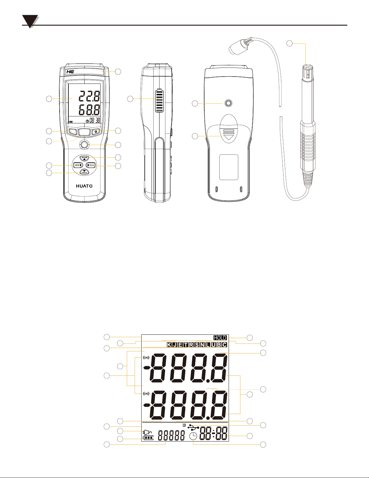
1.2.5 Temperature and Humidity Data Logger Appearance. 6
1.2.6 Temperature and Humidity Data Logger Screen .......... 7
1.3 Button function instructions ....................................................... 8
4.1 LCD Screen Dim .......................................................................... 15
4.2 Data & Time Error ........................................................................ 15
4.3 Software "Runtime Error" .......................................................... 15
4.4 Check COM Port Number ......................................................... 15
Section 2 Instal2ation and Instruction .......................................................... 9
Section 3 Attention ............................................................................................. 15
Section 4 FAQ ...................................................................................................... 15
2.1 Software Installation ................................................................... 9
2.1.1 The Requirement of the Computer Hardware ............... 9
2.1.2 Install Driver & Software................................................... 9
2.2 How to Read and Configure the Logger ................................. 10
2.2.1 Read and Configure the Logger's Settings ..................... 10
2.2.2 Setting Parameters Description ........................................ 11
2.3 Download the Logging Data ...................................................... 12
2.4 View Data Sheet ........................................................................... 13
2.5 Exporting Logs from LogPro ..................................................... 13
2.6 Delete Records in the Logger ..................................................... 14
2.7 Check the Save File in File List .................................................. 14

HE70X-80X series is thermocouple thermometer. It can support 8 types thermocouple
sensors (such as K, J, E, T, N, S, R, B), measuring -200degC to 1800degC with different
sensor type suitable for the exact applications. HE70X-80X series are widely applied
in industrial production fields, food processing industry, pharmaceutical industry
and research testing fields as well as other temperature monitoring applications.
1.1.2 - Features
• 4 Channels T1/T2/T3/T4 temperatures are displayed separately.
• Manual recording and reading functions (88 groups), large capacity broken
storage, can store 36,000 sets of data.
• The input isolation protection voltage is 350Vp-p between any channel.
• Unique design, ergonomics, protection of the sensor, beautiful appearance.
• Host Size(L x H x D): 189mm x 69mm x 44mm.
• LCD Screen Size: 54mm x 44mm.
1.1.3 - Application
• Industrial production.
• Food processing.
• Pharmaceutical.
• Research
There are no user serviceable parts inside your unit. Attempting to repair or service your
unit may void your warranty.
Introduction
1
NOTE:
1
1.1.1 - Introduction
Section 1.1 - HE70X and HE80X product introduction
1.1.4 - Data Logger Model
Model Temperature
Channel
Temperature
Accuracy
Handheld Recording
Capacity
Measuring
Range
Auto Recording
Capacity
HE701
±0.8℃±2‰FS
±0.8℃±2‰FS
-200~1800℃
36,000
(none)
88
-200~1800℃88
HE702
HE704
HE801
HE802
HE804
1
2
4
1
2
4

1.1.5 - Temperature Data Logger Appearance
(HE701/HE702/HE704/HE801/HE802/HE804)
1.1.6 - Single-channel LCD Screen (HE701 ,HE801)
2
Introduction 1
9.
10.
11.
12.
13.
14.
15.
16.
Manual recording function button
Model label
USB port & DC power Jack
(9V, 3.5mm)
Hole for fixed frame
Battery cover
701/801 cap(sensor port)
702/802 cap(sensor port)
704/804 cap(sensor port)
1.
2.
3.
4.
5.
6.
7.
8.
LCD Screen
LOG Button
Setup Button
ON/OFF
OK Button
Maximum and minimum
checking buttons
Manual recording data
checking button
The previous data checking
button
+
T1
_
+
T1
+
T2
+
T3
+
T4
_ _ _ _
+
T1
+
T2
_ _
10
4
5
6
7
1 11
12
14
15 16
13
2
8
9
3
DATA LOG GER
THERMOM ETER
804
LOG SETUP
IN
OK
1
2
3
4
5
6
7
8
9
10
11
20
19
18
14
13
12
17
16
15
DEL
MIN
MAX
REL
SETUP
TYPE:
HIGH LOW
LOG
MEM
℃
℉
℃
℉

Introduction
1
3
1.1.7 - Two-channel LCD Screen (HE702 ,HE802)
11.
12.
13.
14.
15.
16.
17.
18.
19.
20.
Count for auto-recording and
manual-recordingdata.
This symbol shows being the
manual-recording checking status.
Clock symbol.
Time display area.
This symbol shows instruments being
the connection status with PC.
Maximum and minimum data display area.
This symbol shows being the maximum or
minimum data checking status.
Symbol for temperature unit.
This symbol shows being the backlight
status.
This symbol shows the setting limits are
being exceeded.
1.
2.
3.
4.
5.
6.
7.
8.
9.
10.
Sensor type symbol display area.
Temperature data display area.
This symbol shows being the
setup status.
This symbol shows being the manual
recording data checking status.
This symbol shows being the maximum
and minimum data checking status.
This symbol shows being the holding
fixed measuring data status.
This symbols shows that data can be
deleted.
This symbol shows instrument is
supported by external DC power.
Battery status indication.
This symbols shows being the logging
status (HE80x only).
10.
11.
12.
13.
14.
16.
17.
18.
Count for manual-recording or
auto-recording data
Symbol for clock
Year/month-date/clock alternate display area
Instrument is being connected with PC.
Manual-recording data checking status.
Display area for channel 1 and channel 2.
Symbols for temperature unit for channel 1
and channel 2.
Maximum or minimum data checking status
Holding fixed measuring data status
1.
2.
3.
4.
5.
6.
7.
8.
9.
Setup mode.
Maximum/Minimum data checking
status.
Sensor type symbol display area
Symbol for channel 1 and channel 2.
Shows that the setting limits for channel
1 or channel 2 are being exceeded.
logging status(HE80x only).
Manual-recording data can be deleted.
Instrument is being supported by DC
external power Battery status indication.
Battery status indication.
TYPE:
SETUP HIGH LOW
MAX
MIN
℃℉
℃℉
DEL
LOG
MEM
T1
T2
4
3
2
1
5
7
6
8
9
10
18
16
15
13
12
14
11
17

Introduction 1
4
10.
11.
12.
13.
14.
15.
16.
17.
18.
Count for auto-recording or
manual-recording data.
Symbol for clock.
Manual-recoding data checking status.
Instrument is being connected with PC.
Manual-recoding data checking status.
Setting limits are being exceeded.
Temperature unit for channel 1, channel
2, channel 3 and channel 4.
Maximum and minimum data checking
status.
Holding fixed measuring data status.
1.
2.
3.
4.
5.
6.
7.
8.
9.
Setup mode.
Maximum or minimum data checking
status.
Sensor type symbol display area.
T1,T2,T3,T4 for channel 1, channel 2,
channel 3 and channel 4 respectively.
Data symbol for channel 1, channel 2,
channel 3 and channel 4.
Logging status (HE80x only).
Manual-recording data can be deleted.
Instrument is being connected with PC.
Battery status indication.
1.1.8 - Four-channel LCD Screen (HE704 ,HE804)
1
2
3
4
515
14
13
12
11
16
17
18
6
7
8
9
10
TYPE:
SETUP HIGH LOW
MAX
MIN
℃℉℃℉
℃℉ ℃℉
DEL
LOG
MEM
T3
T1 T2
T4

Introduction
1
5
HE81x series Temperature and Humidity Data Logger, they are Comprehensive
temperature and humidity measuring instruments which can measure the RH, air
temperature, it has advanced functions such as backlight, check for MAX and MIN
value and USB port telecommunication to download all recorded data.
1.2.2 - Features
• Adopt Swiss imported high precision temperature and humidity sensor.
• Manual recording and reading functions (88 groups), large capacity broken
storage, can store 36,000 sets of data.
• Unique design, ergonomics, protection of the sensor, beautiful appearance.
• Host Size(L x H x D): TH Series (275mm x 69mm x 44mm)
EX Series (189mm x 69mm x 44mm).
• LCD Screen Size: TH/EX Series (54mm x 44mm).
1.2.3 - Application
• Industrial production.
• Food processing.
• Pharmaceutical.
• Air Condition / Heater Test.
There are no user serviceable parts inside your unit. Attempting to repair or service your
unit may void your warranty.
NOTE:
1.2.1 - Introduction
Section 1.2 - HE81X product introduction
1.2.4 - Data Logger Model
Model Temperature
Range
Humidity
Range
Humidity
Accuracy
Temperature
Accuracy
Auto Recording
Capacity
HE810-TH 0~100%RH
0~100%RH
±0.5℃
36.000
±5%RH
±0.3℃±3%RH
HE810-EX
HE815-TH
HE815-EX
-20~70℃
-40~85℃
-20~70℃
-40~85℃

Introduction 1
8.
9.
10.
11.
12.
13.
14.
The previous data checking button
Manual recording function button
Model label
USB port & DC power Jack
(9V, 3.5mm)
Hole for fixed frame
Battery cover
Built-in sensor
1.
2.
3.
4.
5.
6.
7.
LCD Screen
LOG Button
Setup Button
ON/OFF
OK Button
Maximum and minimum
checking buttons
Manual recording data checking
button
1.2.5 - Temperature and Humidity Data Logger Appearance
(HE810-TH/HE810-EX/HE815-TH/HE815-EX)
6
10
4
5
6
7
111
12
14
13
2
8
9
3
DATA LOG GER
810
LOG SETUP
IN
OK
HYGRO-THE RMOMETER
HE810-TH/HE815-TH
HE810-EX/HE815-EX)
15
Ch1

8.
9.
10.
11.
12.
13.
14.
15.
The previous data checking button
Manual recording function button
Model label
USB port & DC power Jack (9V, 3.5mm)
Hole for fixed frame
Battery cover
External Cable Length 3 meter
81x-EX Cap(Sensor Port)
1.
2.
3.
4.
5.
6.
7.
LCD Screen
LOG Button
Setup Button
ON/OFF
OK Button
Maximum and minimum checking
buttons
Manual recording data checking
button
7
Introduction
1
10
4
5
6
7
1 11
12
14
13
2
8
9
3
DATA LOG GER
HYGRO-THE RMOMETER
810
LOG SETUP
IN
OK
1.2.6 - Two-channel LCD Screen
(HE810-TH/HE810-EX/HE815-TH/HE815-EX )
TYPE:
SETUP HIGH LOW
MAX
MIN
℃℉
℃℉%RH
DEL
LOG
MEM
T1
T2
4
3
2
1
5
7
6
8
9
10
19
16
15
13
12
14
11
17
18
℃
%RH

Introduction 1
8
10.
11.
12.
13.
14.
16.
17.
18.
19.
Count for manual-recording or
auto-recording data
Symbol for clock
Year/month-date/clock alternate display area
Instrument is being connected with PC.
Manual-recording data checking status.
Display area for channel 1 and channel 2.
Symbol for Humidity unit
Symbols for temperature unit for channel 1
and channel 2.
Maximum or minimum data checking status
Holding fixed measuring data status
1.
2.
3.
4.
5.
6.
7.
8.
9.
Setup mode.
Maximum/Minimum data checking
status.
Sensor type symbol display area
Symbol for channel 1 and channel 2.
Shows that the setting limits for channel
1 or channel 2 are being exceeded.
logging status(HE80x only).
Manual-recording data can be deleted.
Instrument is being supported by DC
external power Battery status indication.
Battery status indication.
Section 1.3 - Button function instructions
:Click to turn on the instrument and press long for 3 seconds to turn it off.
Automatic shutdown in 15 minutes.
:Click to enter into the logging mode, click again to exit the logging mode.
(HE8XX only)
:Setup switch button during the setup mode.
Backlight button during the normal working mode
:Direction button during the setup mode.
Maximum/minimum data checking button during the normal working mode.
:Direction button during the setup mode.
Button for checking the previous manual-recording data during normal working
status.
:Direction button during the setup mode
Button for checking the manual-recording data during normal working status,
total in 88 (capacity)
:Direction button during the setup mode
Holding the fixed measuring data status during the normal working mode
:Click to enter into the setup mode, click again to exit the current mode and save
the settings.
1、℃/ ℉switching button, usually ℃, switch ℃/ ℉,℉lighting, OK
to enter into the next setting mode.
2、SETUP DEL MEM: show DIS in the LCD corner means CAN’T, switch,
show En and press OK to delete the manual-recording data.
3、SETUP DEL LOG: show DIS in the LCD corner means CAN’T, switch,
show En and press OK to delete auto-recording data
4、SETUP TYPE: lighting from K, moving on one by one, OK key to
confirm the sensor type.

9
Installation and Instruction
2
2.1.1 - The Requirement of the Computer Hardware
Section 2.1 - Software Installation
Section 2 - Installation and Instruction
1. OS: Windows XP/Vista/8/10 (32/64bit).
2. CPU: 1.6GHz.
3. Physical Memory: 512MB.
4. Hard-drive Space: 4 GB.
5. USB Port: 1.
This section will explain how to use the software to upload, read, configure and
synchronize the settings, how to turn on/off the logger & enter/exist the logging
mode, and how to delete and download the logging data.
2.1.2 - Install Driver & Software
Note: "If need to install Driver separately, please install 64 bit driver for Windows 64 bit computer
& 32 bit driver for Windows 32 bit computer".
1. Install LogPro Software and Driver together(Default Path: C:\81x Logger).
2. Installation Steps: When enter the software, click the ‘Install LogPro and Driver’
(as below Pic ), and then click the ‘Next ’(5 times), click the ‘Install’, click the ‘Finish’.
When entering the LogPro software interface, the installation driver software
window will pop up. Click 'Install', and the success of installation will be displayed.
Install driverThe successful installed
Default installation folderLogPro installation page
5

2.2.1 - Read and Configure the Logger's Settings
1. Turn on and Insert the data logger to the computer¹.
2. Start LogPro software on the PC.
3. From the toolbar select Connect.
4. Load & Read the logger’s current settings.
5. Configure the new settings.
6. Sync the settings & time. (The PC time will be synchronized to the logger
as well.) .
7. From the toolbar select disconnect.
8. Sync the Computer's Data & Time to the Data Logger.
9. Unplug the logger from the computer, and then the logger is in Standby mode.
8
1. The windows operating system cannot handle USB devices being unplugged and plugged back too fast. When
unplugging the logger, wait for about 5 seconds before plugging it in again. If you unplug and plug back a device
too quickly, the computer may stop recognizing any USB devices on that port. If this happens you will have to
restart the computer. This is a windows USB problem and is not related to LogPro.
Installation and Instruction 2
Section 2.2 - How to Read and Configure the Logger
10
S100-TH
HS100CH642
4
5
7
3
6

11
Installation and Instruction
2
2.2.2 - Setting Parameters Description
Calibrate the logger: The logger is factory calibrated to an accuracy given in the device specifications. However, there may be times when you
wish to adjust the calibration of your logger. Logpro provides you with the ability to perform a single point offset calibration. This calibration
can be used to increase the accuracy of the logger for a restricted data range.
Name HE804
HE804CK277
data logger
HE804
GA25D
60
10
1
100
0
SN
Type
Model
Firmware
Sampling Interval(Secs)
300
Logging Interval(Secs)
Logs
Manu
36738Total
CH1 High
CH1 Low
100CH2 High
A.System
B.Sampling
C.Storage
Alarm Threashold
Setting Parameter Text Description
Name English letters or numbers Name of the logger
SN 10 characters Must be the same as the one in the
label of logger
Temperature Celsius & Fahrenheit Select the Celsius and Fahrenheit readings
Logging Interval (secs)
sampling Interval (secs)
Number from 2 to 86400
Number from 1 to 240
Logging frequency
Sampling frequency in LCD screen
Logs The count of records in the memory
Total The total capacity of the logger’s storage
Offset
Input positive number to decrease the
value. Input negative number to increase
the value.
Number from 0 to 43000
Number 43000
Calibration mode: For example,
pls fill in 1.5 if the displayed
temperature is higher than the
actual temperature of 1.5 ℃; fill
in -1.5 if the displayed
temperature is lower than the
actual temperature of 1.5 ℃. If
you need toadjust the humidity,
do the same, thenumber field is
-100~100.

Installation and Instruction 2
Section 2.3 - Download the Logging Data
10. Insert the data logger to the computer.
11. Start LogPro software on the PC.
12. From the toolbar select Connect.
13. From the toolbar select Download.
Once the data is downloaded from the logger to the PC, the log graph will be displayed.
Tips: Press and hold the left mouse button to drag a box, when the left mouse button is
released, the graph will be redraw with the data in the selected rectangle area. Click right
button, then the graph will be redrawing with all the data in the logs file.
12
HS100CH642
S100-TH
13
12

13
Section 2.4 - View Data Sheet
Click “Data List” button on the toolbar, and then the data listing window
is shown below. Channel 3 unit is Dew Point. The Value is calculated from
temperature & humidity.
The data pane lists the data samples collected by the logging device.
The column width of each column is adjustable by using the left mouse button
and dragging the column the desired width.
Section 2.5 - Exporting Logs from LogPro
• Export data list to an Excel file.
• Export data list to a PDF file.
• Export graph to a BMP file.
Installation and Instruction
2

Installation and Instruction 2
Section 2.6 - Delete Records in the Logger
14. From the toolbar select Delete.
14
Section 2.7 - Check the Save File in File list
15. From the toolbar select File List.
16. Click to open the file.
• Double click left mouse button, then the selected file is opened.
• Click right mouse button, a popup menu is shown as below, you can
rename or delete or log file.
• The save file is saved in the LogPro software’s installation path in the PC’s
hard driver.
15
16
14

Attention
3
• HE70x/80x/81x are not waterproof. Do not connect loggers with computer
when the logger is on water.
• Plastic shell is ABS, flame retardant, not resistant to acid and alkali.
• If repair is needed, only authorized technician could do the repair.
• The instrument configuration by 1 x 6LR61 (9V) battery is not rechargeable.
• USB power supply (5V) cannot let the Data Logger work.
Section 4.1 - LCD Screen Dim
Section 4.2 - Recording (LOG) are Automatically Stop
Reason:
• When the battery level is low, there will not be sufficient power to support
recording function of the logger.
Solution:
• Replace the battery.
Reason:
• Insufficient battery or the environment temperature is too low or too high.
Solution:
• In the case of insufficient battery, please replace the battery. If resulted from
environment temperature, please immediately take the logger out of the
environment.
Section 4.3 - Software “Runtime Error”
Reason:
• OS forbid software creating files.
Solution:
• Run the program (software) as an administrator.
• Install software in D or E drive if available.
• A data logger name cannot contain any of the following characters: \ / :
* ? “ < > |
• Software’s installation path cannot include Chinese character or garbage
character.
Section 4.4 - Check COM Port Number
Press “Win” + “R” in keyboard -> Run “devmgmt.msc” to Open “Device
Manager” in Windows-> Expand “Ports (COM & LPT)” -> “USB-serial CH340
(COM No.)” is the Data Logger.
FAQ
4
15
This manual suits for next models
8
Table of contents
Other Huato Thermometer manuals