Hunza ULTRA 35 Wall Spot User manual
Other Hunza Outdoor Light manuals

Hunza
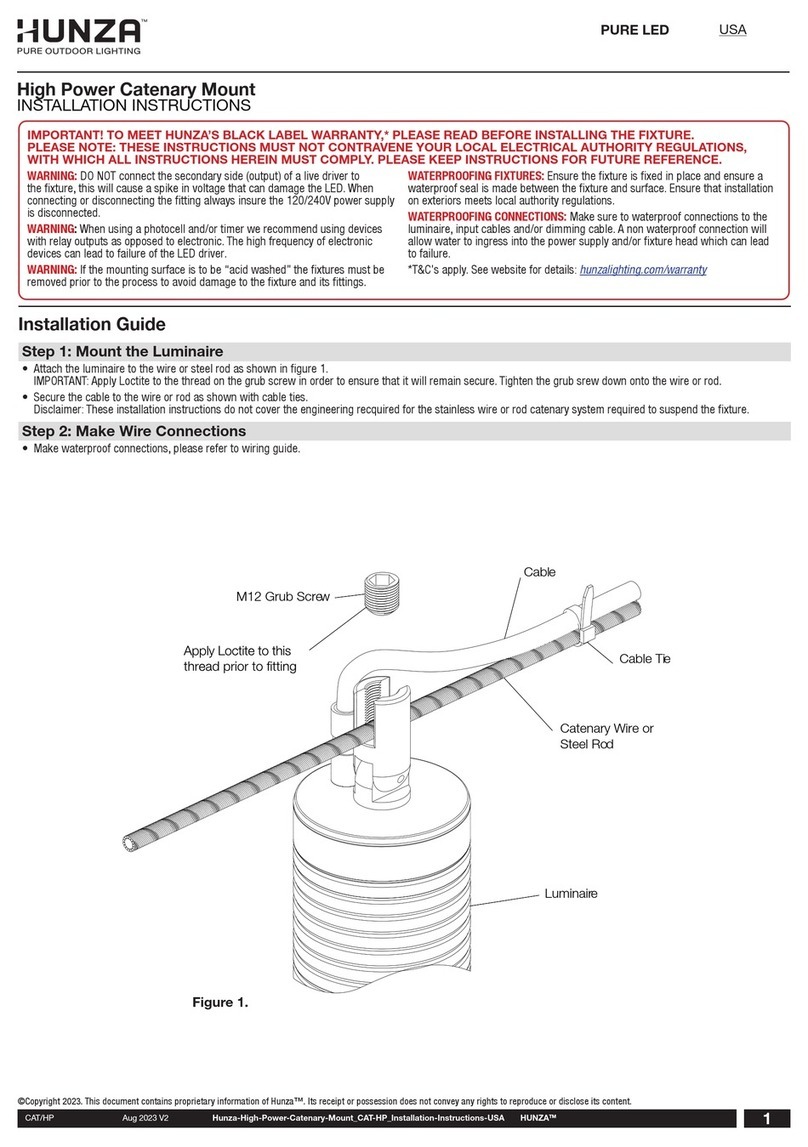
Hunza CAT/HP User manual

Hunza
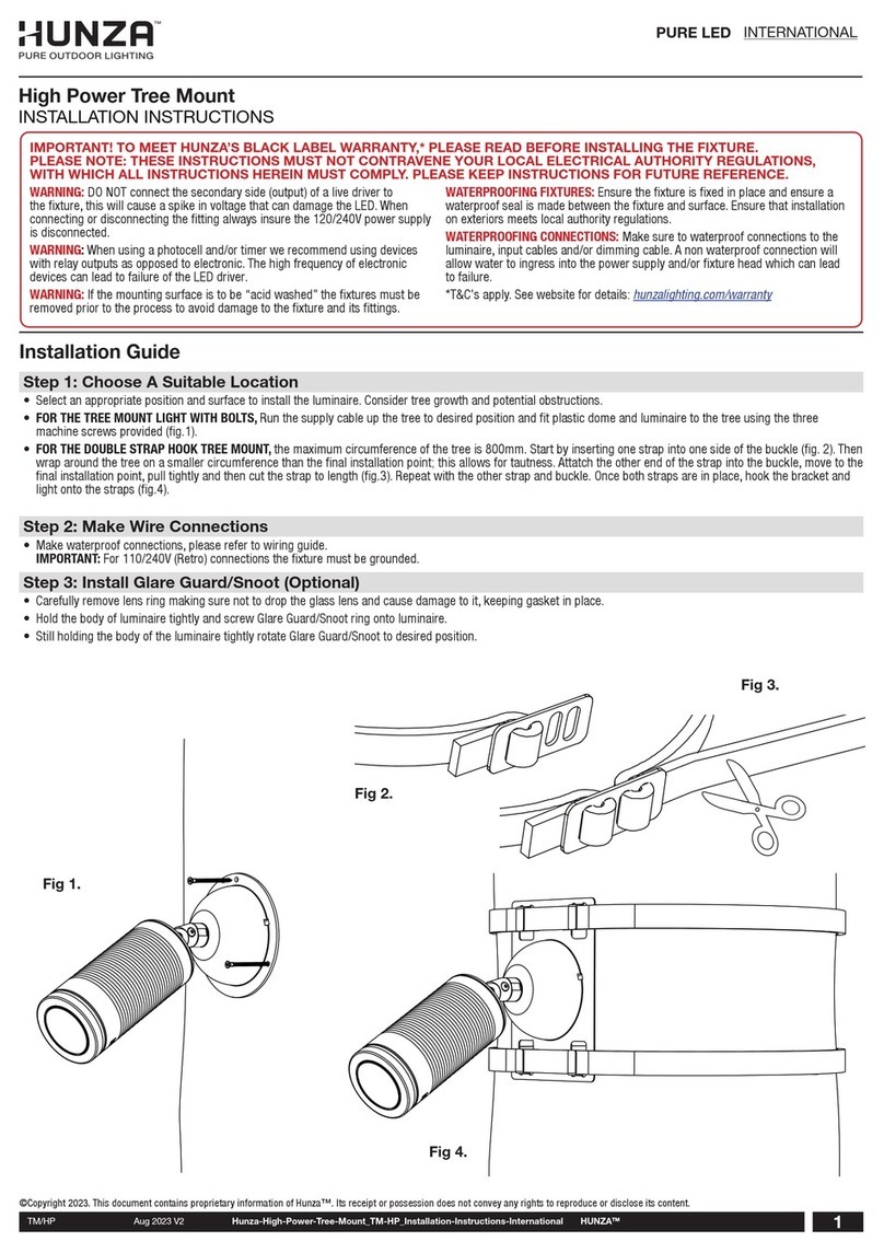
Hunza TM/HP User manual

Hunza
Hunza POND/HP User manual

Hunza
Hunza SAFETOUCH 50 LED User manual

Hunza
Hunza CAT/HP User manual

Hunza
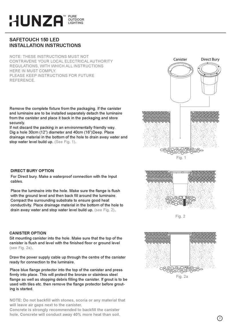
Hunza SAFETOUCH 150 LED User manual

Hunza
Hunza SAFETOUCH 100 LED User manual

Hunza
Hunza CATENARY MOUNT HIGH POWER User manual

Hunza
Hunza PS/HP User manual
Popular Outdoor Light manuals by other brands

HEPER
HEPER DOGO Side LW6048.585-US Installation & maintenance instructions

Maretti
Maretti VIBE S 14.6080.04.A quick start guide

BEGA
BEGA 84 253 Installation and technical information

HEPER
HEPER LW8034.003-US Installation & maintenance instructions

HEPER
HEPER MINIMO Installation & maintenance instructions

LIGMAN
LIGMAN BAMBOO 3 installation manual

Maretti
Maretti TUBE CUBE WALL 14.4998.04 quick start guide

Maxim Lighting
Maxim Lighting Carriage House VX 40428WGOB installation instructions

urban ambiance
urban ambiance UQL1273 installation instructions

TotalPond
TotalPond 52238 instruction manual

Donner & Blitzen
Donner & Blitzen 0-02661479-2 owner's manual

LIGMAN
LIGMAN DE-20023 installation manual


