3
Section 1: Safety
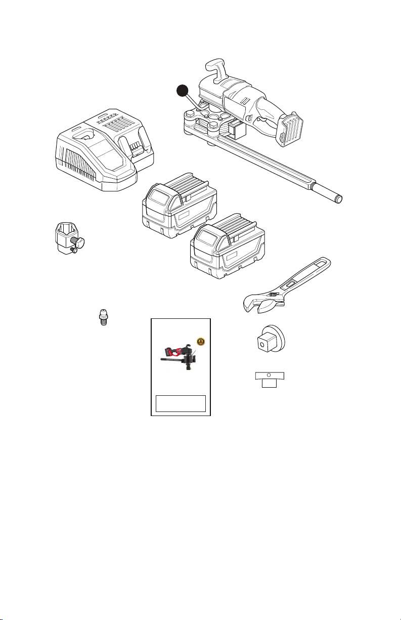
The HH500 is designed to produce an intense amount of torque.
PLEASE USE EXTREME CAUTION AT ALL TIMES.
This tool has been designed to help operators open and close
valves. The tool can create in excess of 450 lb-ft of torque.
DANGER
The incorrect use of HH500 equipment may cause
serious injury. Read these instructions in their
entirety before using any HH500 products.
WARNING
Use caution when operating any power tool. Read
and follow the operating and safety instructions in
the product manual. Always wear safety goggles
and other appropriate safety items for protection.
CAUTION
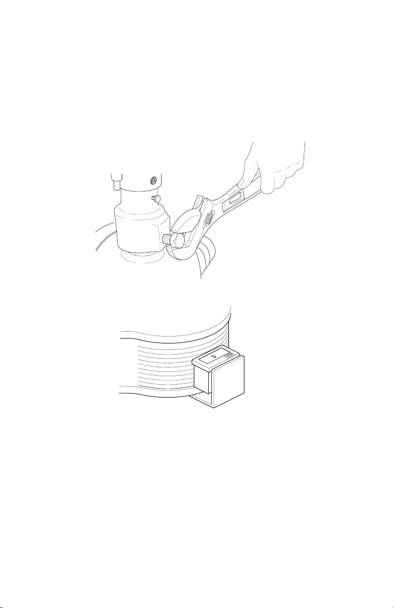
Never apply manual torque to open or close a valve! ONLY
USE MOTOR POWER TO ACTUATE THE VALVE,
OTHERWISE, DAMAGE TO THE MOTOR MAY OCCUR.
WARNING
MAKE SURE THE REACTION HANDLE IS PULLING
AWAY FROM THE OPERATOR DURING USE. Misuse
could lead to loss of operator balance and potential fall
injury.