Husqvarna PG680 Owner's manual

PG680/820 Frequency Inverter Programming
The PG680 & PG820 both come equipped with frequency inverters. The
functions of these frequency inverters are as follows:
•Maximise performance of the drive motors.
•Enable Forward/Reverse control of drive motors.
•Enable speed control of drive motors.
•Regulatory / Protective functions.
•Diagnostic & Servicing functions.
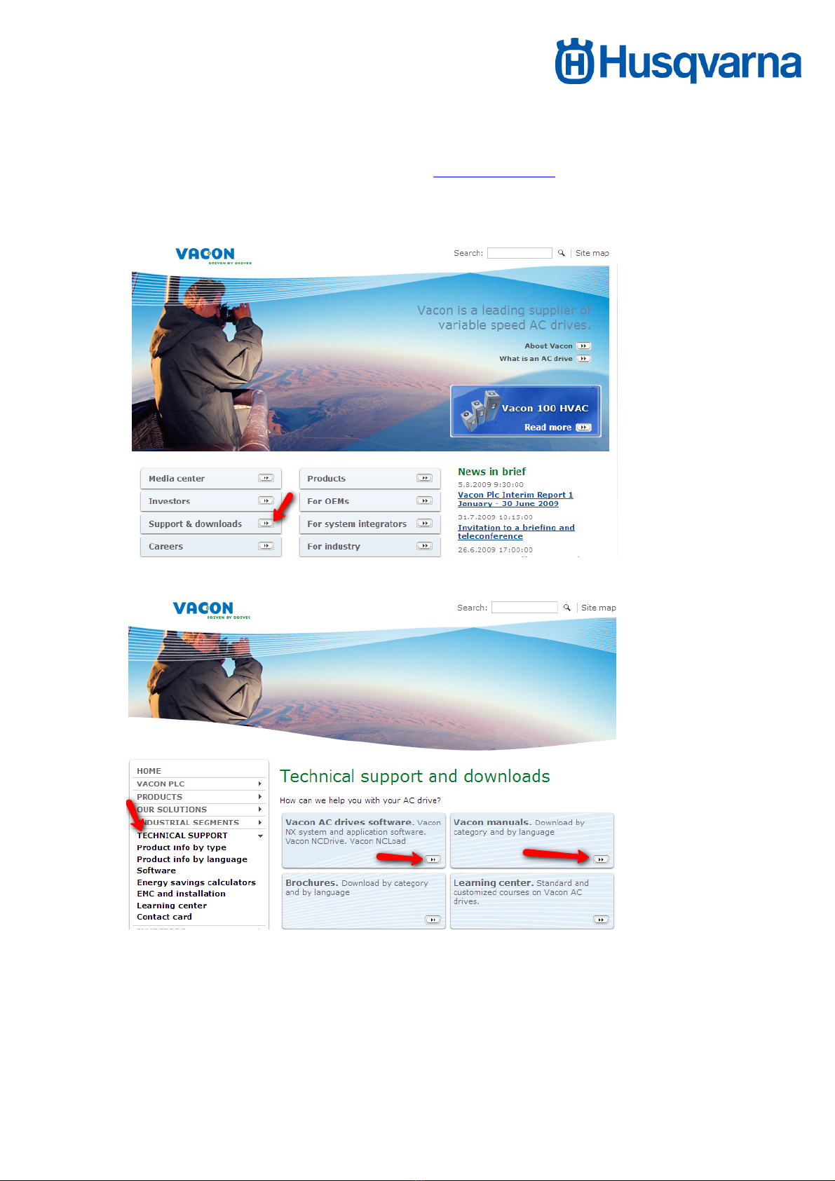
From time to time, updates will be made available to help further enhance the
above features. These updates can be uploaded into the frequency converters
using a personal computer / laptop device.
Two different software packages are required for such updates:
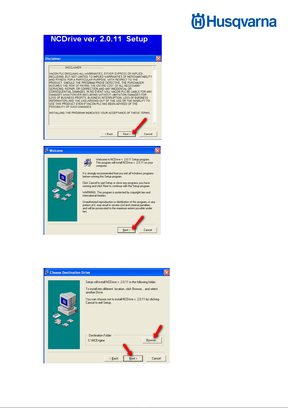
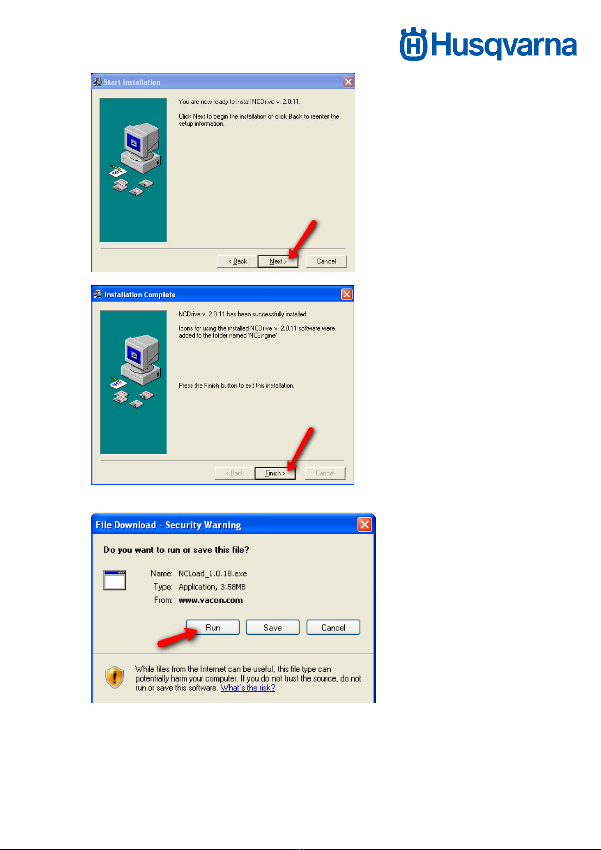
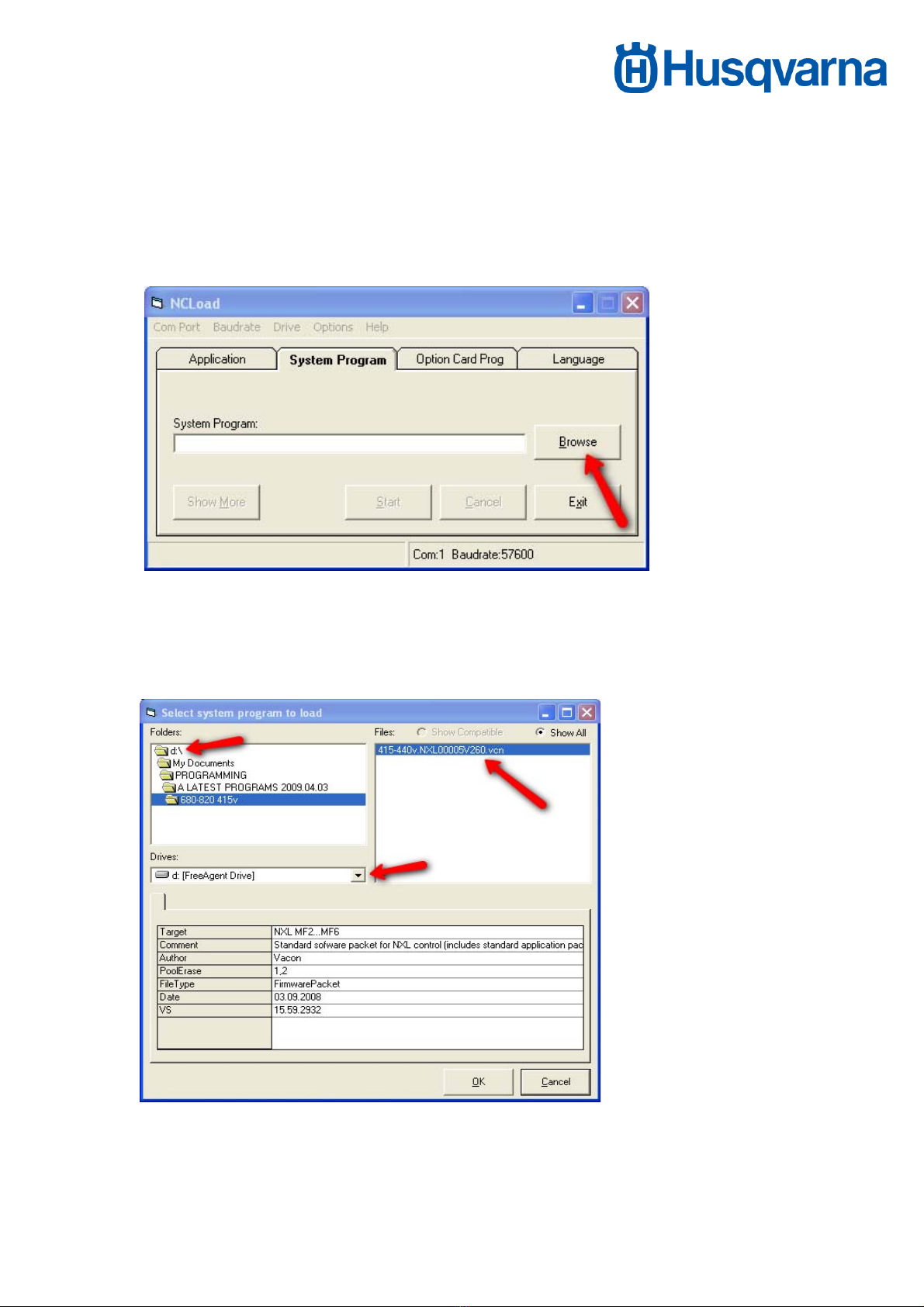
•NCLoad – installs operating system into frequency converter.
•NCDrive – installs settings / parameters specific for our application into
the frequency inverters.
The following manual covers:
1. How to set-up the personal computer / laptop device which will be used
to install the updates to the frequency inverters.
2. How to install the updates into the frequency converters.

NCLOAD and NCDRIVE Programming tools,
Before any programming can commence the correct software is needed, this
can be found and downloaded for free at www.vacon.com
You can find it in:
Supports and downloads
-Technical support
Select: Vacon AC drives and software
(You may like to also get a copy of the NXL manual in which case select Vacon
Manuals – then select option “6 – Vacon NXL manuals” – then select the
language of your choice.)

Once in Vacon AC drives software, install both NCDrive and NCLoad by
clicking on the buttons as shown in the below image.
Select “RUN” to automatically install the software. You will not need to allocate
where you would like to save both the NC Drive and NC Load program, they
will go straight to your hard drive
-Vacon NCDrive -“Run” then navigate through each window option

Both NCDrive and NCLoad will automatically be placed in C:\NCEngine when
“Next” is selected. If you require a different target location, select using the
“Browse” option (not recommended).

-Vacon NCLoad -“Run”
Run will both save and open the program for you.

PG 680/820 Programming
Once both NCLoad and NCDrive programs have been successfully installed on
your computer, you will also require the following components:
-USB to Serial port adapter (501 36 98-01)
-Vacon extension cable *** (575 66 43-01)
-Vacon adaptor panel (510 37 24-01)
*** Extremely important this is a genuine item as generic DB9 cables are wired
differently!
Note: When using USB to Serial port adaptor (501 36 98-01) for the first time,
you will need to install the driver (which is located on the CD accompanying the
adaptor) via the “found new hardware wizard”. (Microsoft Windows will
automatically prompt you to do this when the adaptor is plugged in to the
computer).
Once you have these parts and all installations are complete, you are ready to
update or install the frequency converters with the latest version of the
Husqvarna Surface Preparation operating parameters.
Note:
Installations into the frequency inverters should always be done in the following
order:
1. NCLoad – operating system update.
2. NCDrive – settings / parameter update.

INSTALLATIONS USING NCLoad.
Open NC load (using Windows desktop shortcut)
Using the Browse option, select the operating system file (.vcn) you wish to
install (for this example we will use -NXL00005V260.VCN) into the frequency
inverter.
The first time you run NCLoad you may need to manually select the file path
(including Drive, Folder and File) for the NCLoad program as to where you
have the programming files saved, after this NCLoad should remember the
path for any future installations. Once selected press “OK”.
-Set Baudrate to maximum speed “57600” (This will ensure the installation goes
the fastest.)

- Select correct COM Port setting. This will need to be set inline with computer /
laptop since Windows will automatically assign a COM Port setting to the USB
to serial Port Adaptor when the adaptor is plugged into your computer / laptop.
To check which COM Port setting should be selected in NCLoad, follow the
following procedure:
Go to Start/ My Computer and Right click on Properties
Once in the Properties window go to Hardware / Device Manager
Then find the Port (COM & LPT) to check which COM Port Windows has
assigned the adaptor to (in this case COM1)

COM Port settings may vary from computer to computer. If the COM Port
setting assigned by Windows is above 8, then we will experience a
communication problem when using NCLoad & NCDrive since both programs
only offer 8 options for COM Port selection. If on your computer / laptop
Windows has assigned a COM Port setting higher than 8, please change as
shown below.
Right click on USB to serial comm. Port
Go to Properties / Port Settings / Advanced.

Here you will find a box enabling you to change the COM Port setting. Change
the COM Port setting to number “8” or below and not already in use. Then click
“OK” twice so you exit back to Device Manager. The new COM Port setting
that you have selected for ATEN USB to Serial Bridge should now be visible.
This is the COM Port setting you need to select in NCLoad and NCDrive.
Note:
For each future software installation into the frequency inverter you perform, it
is important you insert the USB to Serial port adapter into the same USB port in
your computer / laptop. If you insert into a different USB port, Windows will
assign it to a different COM Port setting in which case you will need to change
the COM Port setting in NCLoad & NCDrive and possibly also in Device
Manager.
Once you have finished checking the COM Port setting above, continue with
COM Port selection in NCLoad.
Once the Programming file and COM Port have been selected then click
“Start”.

“Loading loader” will appear in the left hand corner of the window, this may take
a few minutes to complete.
“Ready!” in the bottom left hand corner of window indicates successful down
load, you need this to be able to continue to the next step of parameter
installation.

NCLoad Trouble Shooting
-“Error in opening comport”
- Check cable connection
- Are you connected to frequency converter?
- Is the frequency converter powered up?
- Check the COM Port settings in Windows and NCLoad match (as
outlined in previous section).
“Target Sync failed”
This may occur when the computer is not recognising the frequency converter
- Check your cable connection
- Are you connected to frequency converter?
- Is frequency converter powered up?
- Check that the Vacon adaptor panel is connected properly Vacon
adaptor panel
- Check that the Vacon adaptor panel is not damaged (check pin ports
on back of card)
- Do you have the correct Vacon extension cable; a generic 9 pin cable
will not work.
- Try different USB ports/-retry against different comport settings
Once the operating program has been successfully installed, you are ready to move on.
Close NCLOAD!
This is very important as the NC LOAD and NC DRIVE programs both read
some of the same data to preform their tasks. This can cause operation
conflict when both programs are open at the same time.

INSTALLATIONS USING NCDrive.
Open NC load (using Windows desktop shortcut)
Select Tools / Options / Communication.
Set Baudrate to 57600 (Apply)
Check comport settings are the same as per NCLoad.

Opening the Parameter file
Go to File
The first time you run NCDrive you may need to manually select the file path for
the NCDrive program as to where you have the parameters files saved, after
this it should remember the path for any future installations.
Select the parameter file (.par) you wish to install and click “Open”.
Unlike in NCLoad where we use the same system software for both frequency
converters, in NCDrive, we have separate parameter files for each frequency
converter. In this example we will use the following files:
- 1kW-820 & 680 - 400V STANDARD APP when connecting to the larger
frequency converter.
- 3kW-820 & 680 - 400V STANDARD APP for the smaller frequency converter
When selected, the file will open with full parameter listings appearing on the
screen.
Select “Download” tab (the correct terminology should really be upload) to
install parameters from computer to frequency inverter.

When the “Download” begins there will have a few pop up windows the first is
to be ignored and has no relevance to our application.

The second window may say that some parameters could not be copied, or
have a different application, this is not a problem and what we are actually
addressing, click Download anyway
Parameters will automatically install.

NCDrive Trouble Shooting
“Communication Error!”
- Check the USB to Serial port adapter and the Vacon extension cable
are connected properly and securely
- Check the Vacon adaptor panel is properly inserted.
- Check Vacon adaptor panel is not damaged (check pin ports on back
of panel)
- Check comport settings
- Use the Device Manager in Windows to check the comport settings
as outlined in NCLoad Trouble Shooting
- Check you have a genuine extension cable.
Once installation is complete, a green ready indicator can be seen at the
bottom of the screen informing you that the parameters have been received by
the frequency converter. The LOADED sign should also appear at the top of
the window.


CHECKING YOUR INSTALLATION.
Successful program installation of the frequency converter can be checked
using the frequency converter display panel when operating the grinding
machine using the switches on the control panel located near the handle bars
of the grinder.
NOTE: ENSURE MOTORS ARE UNPLUGGED BEFORE PERFORMING
CHECKS!
Stop/Run Switch:
The frequency converter pictured below is powered up but still in a “STOP”
mode, this can be seen by the 2nd arrow on the left hand side. It is also
displaying the Output Frequency (default display setting) of the frequency
inverter. Since the machine is in stop mode, the Output Frequency will be
shown as 0.00Hz.
When switch is set to “RUN”
“STOP” will change to “RUN” and the display panel will begin to reflect the
current speed control settings on the speed control dial (potentiometer) on the
control panel near the grinder handle bars.
- Head speed (left hand potentiometer on control panel). When
potentiometer set to zero, display on small frequency inverter should
read 20Hz. When potentiometer set to 10, display on small
frequency inverter should read 120Hz.
- Disc speed (right hand potentiometer on control panel). When
potentiometer set to zero, display on small frequency inverter should
read 20Hz. When potentiometer set to 10, display on small
frequency inverter should read 80Hz.

Direction Switches:
Changes made to the direction switches on the control panel near the grinder
handle bars can only be seen when the machine is in RUN mode.
To check FWD/REV programming of the frequency inverter is working correctly,
set the speed of each potentiometer to full and then switch the machine into run
mode. As mentioned above, the frequency inverters should ramp up to 120Hz
and 80Hz.
Then change the direction of the FWD/REV switches and the frequency
converter should ramp back down to 0.00Hz (this should take 4-5 seconds
and it is very important that it does take this amount of time). They will
then ramp back up to 120Hz and 80Hz in the opposite direction (one direction
will be indicated by a negative (-) sign in front of the frequency value, the other
direction will be indicated as a positive reading).
If the above tests perform as outlined, you can be sure the program
installations have been received properly by the frequency inverters.
Other manuals for PG680
4
This manual suits for next models
1
Table of contents
Popular DC Drive manuals by other brands

Stanley
Stanley SCH20 Original instructions

LOVATO ELECTRIC
LOVATO ELECTRIC VT1 Series instruction manual

Oakcastle
Oakcastle ED100 Instruction guide

Pentair
Pentair PENTEK PSD25PB Installation and operation manual

D+H
D+H LDF 100-L Instructions for use

elero
elero VariEco L RH Operating and assembly instructions