35
rëáåÖ=íÜÉ=ÅççâÉê=ÜççÇ
Correct ventilation
If the cooker hood should be working correctly there
must be an underpressure in the kitchen. It is important
to keep the kitchen w indows closed and have a win-
dow in an adjacent room open.
Important to know
Great care must be taken if the hood is used at the
same time as a burner or fireplace (e.g. gas, diesel, coal
or wood heaters, water heaters, etc.), as the hood will
expel air which is required by these other appliances.
tten d to it by ope n i n g a wi n do w. No t appli c a ble for
cooker hoods use d in recirculation mode.
Do not operate t e fan at a ig er speed t an
necessary. T e low speeds are adequate for
ordinary requirements w ile cooking. T e ig
speeds s ould be used only if food as burnt
w ile cooking, or for ot er strong f umes.
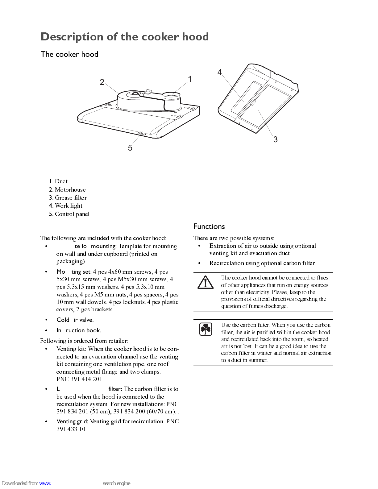
The control panel
The control panel is in the front of the cooker hood.
Best results are obtained by using low speed for
normal conditions and high speed when smells and
steam are more concentrated.
On and Off switch.
Speed adjustment switch.
Lighting switch, on and off.
Turn the hood on a few minutes before you start
cooking then you will get an underpressure in the
kitchen. It should be left on after cooking for about 15
minutes or until all steam and sm ells have disappeared.
j~áåíÉå~åÅÉ=~åÇ=ÅäÉ~åáåÖ
Before doing any maintenance work on t e
ood, disconnect it from t e main supply by
disconnecting t e plug from t e wall socket or
unscrewing t e fuse.
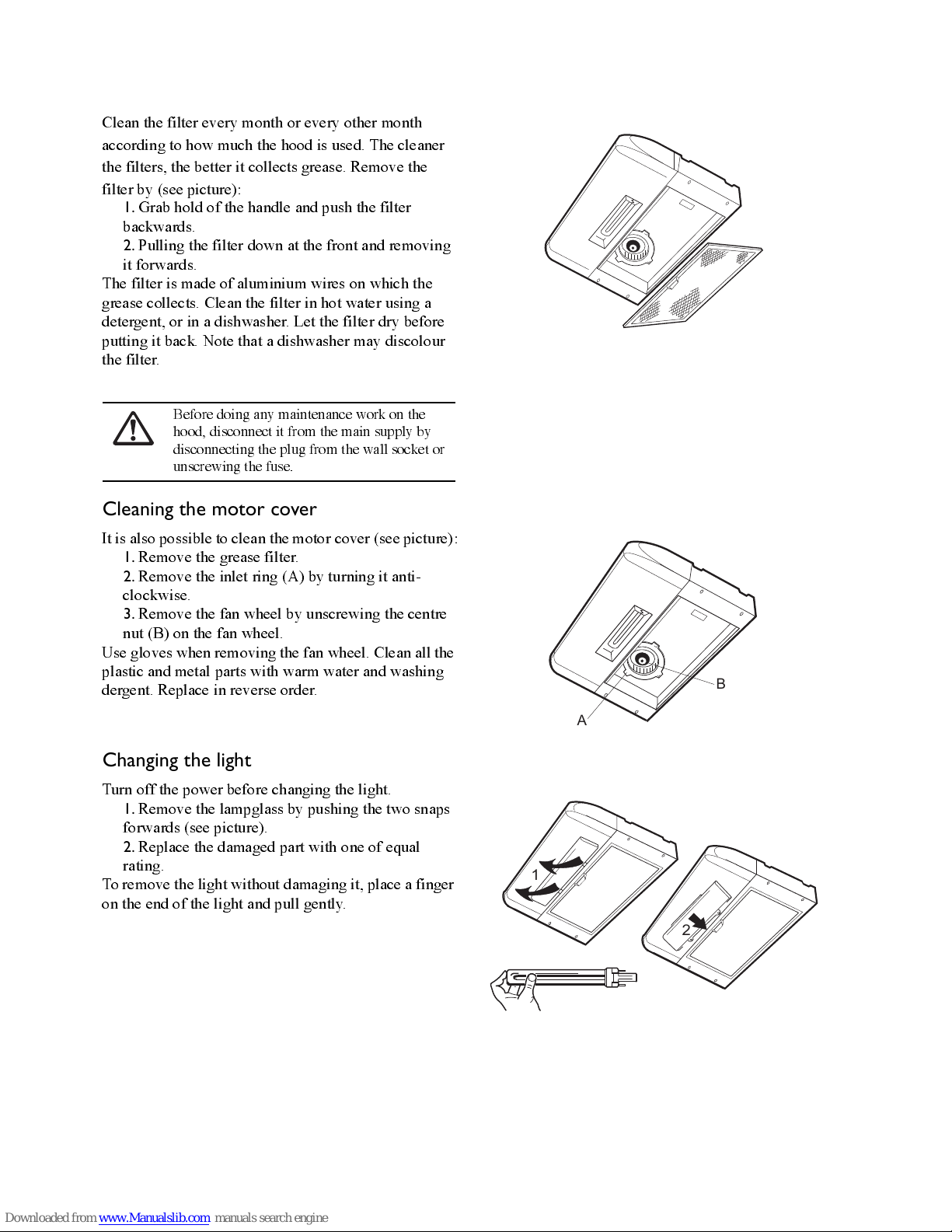
Cleaning the hood
Clean the outside of the hood using a damp cloth and a
mild detergent. Never use corrosive, abrasive or
flammable cleaning products.
Cle an t e filte r regu l arl y. T e g rea se t a t
collects in t e filter and t e duct could ignite if
a ot plate is left on (or if over eating occurs).
Clean t e filter frequently. A clean filter
m in i m i ses t e m o to r lo ad , w ic el ps t e fan
to function more efficiently.
Cleaning/changing the carbon filter
Unlike other carbon filte rs, the LONG LIFE carbon
filter can be cleaned and reactivated. The filter should
be cleaned every other month if use d normally. The
filter is best cleaned in a dishw asher at the highest
temperature using normal washer detergent. The filter
should be w ashed on its own to prevent particles of
food from fastening in it and then causing an
unpleasant smell later on. To reactivate the carbon the
filter should be dried in the oven. Chose upper/lower
heat and maximum 100° C and dry the filter for 10
minutes. Read also the filter instructions.