Hussmann Innovator User manual

Reach-In Glass Door
Innovator, Innovator II &
Innovator III
Spanish 0490775
French 0527088
®
Æ
Installation &
Operation Manual
P/N 0425683_M
February 2019
MANUAL- I/O INNOVATOR DOOR
IMPORTANT
Keep in store for
future reference!

U.S. & Canada 1-800-922-1919 • Mexico 1-800-890-2900 • WWW.HUSSMANN.COM
P/N 0425683_M
ii
This warning does not mean that Hussmann products
will cause cancer or reproductive harm, or is in
violation of any product-safety standards or
requirements. As clarified by the California State
government, Proposition 65 can be considered more of
a‘right to know’ law than a pure product safetylaw.
When used as designed, Hussmann believes that our
products are notharmful. We provide the Proposition
65 warning to stay in compliance with California State
law. It is your responsibility to provide accurate
Proposition 65 warning labels to your customers when
necessary. For more information on Proposition 65,
please visit the California State government website.
August 31, 2018
BEFORE YOU BEGIN
Read these instructions completely and carefully.
PERSONAL PROTECTION EQUIPMENT (PPE)
Personal Protection Equipment (PPE) is required whenever servicing this equipment. Always
wear safety glasses, gloves, protective boots or shoes, long pants, and a long-sleeve shirt when
handling glass.
MISE EN GARDE
AVERTISSEMENT
AVIS
MISE EN GARDE
AVERTISSEMENT
AVIS

Hussmann Corporation • Bridgeton, Missouri 63044-2483 U.S.A.
Innovator Door Installation and Service Instruction P/N 0425683_M
iii
IMPORTANT
KEEP IN STORE FOR FUTURE REFERENCE
Quality that sets industry standards!
12999 St. Charles Rock Road • Bridgeton, MO 63044-2483
U.S. & Canada 1-800-922-1919 • Mexico 1-800-890-2900
www.hussmann.com
© 2019 Hussmann Corporation
Contents
General ......................... 1
Always*Clear™No Fog Glass ....... 1
Shipping Damage ................. 1
New Installations . . . . . . . . . . . . . . . . . . 1
Adjusting Closing Torque ........... 1
Adjusting Door Sag ............... 2
Conditioning Gasket ............... 2
Innovator Door Maintenance ........ 3
Replacing Doors .................. 7
Innovator Door Hinge Replacement .. 9
Replacing Magnetic Gasket ......... 9
Restoring Gasket Seal ..............10
Door Handle Replacement ......... 12
Frame Heater Replacement ........ 12
DASH Controller ................ 14
EcoShine II & EcoShine II Plus
LED Fixture .................. 16
LED Fixture Replacement ......... 17
LED Power Supply Replacement .... 18
Wiring Diagrams for LED Lamps ... 21
Replacement Parts List ............ 24
WARRANTY

U.S. & Canada 1-800-922-1919 • Mexico 1-800-890-2900 • WWW.HUSSMANN.COM
P/N 0425683_M
iv
REVISION HISTORY
REVISION L — FEBRUARY 2019
1. Updated parts list screws, Page 31; California
Warning, Page ii
REVISION K — FEBRUARY 2015
1. Innovator Door Maintenance
2. Innovator Door Hinge Replacement
REVISION J
1. Corrected part numbers, page 12
REVISION I
1. Added EcoShine II Plus LED Lighting, page 12
2. Added EcoShine II / Plus Part Numbers, page 15
REVISION H
1. Added EcoShine II LED Lighting, page 12
2. Added Innovator III part numbers, page 17
Revision G
1. Added Always*Bright LED lighting information,
pages 12 through 18; pages 25, 29 & 30
2. Added Optional Glass Door Anti-Condensate
Heater Controller information, pages 11 & 12
3. Added Always*Bright LED wiring diagrams,
pages 15 & 18
4. Added ballast change-out direction, page 21
* * * * * * * * * * * * * * * * * * * * * * * * * * * * * * * * * * * *
ANSI Z535.5 DEFINITIONS
• DANGER – Indicate[s] a hazardous situation which,
if not avoided, will result in death or serious injury.
• WARNING – Indicate[s] a hazardous sit-
uation which, if not avoided, could result in
death or serious injury.
• CAUTION – Indicate[s] a hazardous situ-
ation which, if not avoided, could result in
minor or moderate injury.
• NOTICE – Not related to personal injury –
Indicates[s] situations, which if not avoided,
could result in damage to equipment.

Hussmann Corporation • Bridgeton, Missouri 63044-2483 U.S.A.
Innovator Door Installation and Service Instruction P/N 0425683_M
1
GENERAL
Be sure merchandisers have been leveled according to
the installation instructions shipped with the reach-in
merchandiser.
The door nameplate is attached to the top of the door,
handle side, behind the magnetic gasket.
The frame nameplate is located on the top left near the
switch.
ALWAYS*CLEAR™NO FOG GLASS
Hussmann recommends using a soft cloth with iso-
propyl (rubbing) alcohol to clean the inside (coated)
glass surface. Isopropyl alcohol does not freeze and
evaporates without leaving residue. Always allow the
surface to dry before closing the door. Use of abrasives
may damage the coated surface and void the warranty.
Labels (stickers) applied to the coated surface will
cause damage and void the warranty.
SHIPPING DAMAGE
All equipment should be thoroughly examined for
shipping damage before and during unloading.
This equipment has been carefully inspected at our
factory. Any claim for loss or damage must be made
to the carrier. The carrier will provide any necessary
inspection reports and/or claim forms.
NEW INSTALLATIONS
Untape the doors and remove shipping braces located
at top and bottom of the doors.
Doors are not fine adjusted at the factory since they
will go out of adjustment during shipment. This is
normal.
ADJUSTING CLOSING TORQUE
Adjust closing torque by turning the bottom hinge pin
in the direction the door closes. Use a 1/2 in. (13 mm)
wrench. Turn the hinge pin until the door closes on its
own, usually 3 to 4 clicks or 3/4 turn. See Figure 1.
DO NOT over-torque the hinge spring assembly.
Excessive torque (over 1 full turn) will result in dam-
age to the spring assembly and/or door. If door does
not close on its own after one full turn (5 clicks), look
for obstructions causing the door to hang up.
Figure 1. Adjusting Closing Torque

U.S. & Canada 1-800-922-1919 • Mexico 1-800-890-2900 • WWW.HUSSMANN.COM
P/N 0425683_M
2
ADJUSTING DOOR SAG
To adjust door sag (saw-tooth effect from door to
door), loosen the two hinge plate mounting screws
using a Torx Plus no. 27 bit. Adjust hinge plate as
needed, then tighten the screws. See Figure 2.
CONDITIONING GASKETS
The manufacturer cannot control the environment
surrounding cases during shipment. Temperature and
humidity fluctuations during shipment, as well as
excessive vibration, may promote gaps between gasket
and frame. These gaps prevent gaskets from sealing
even when correctly fitted at the factory. This is not a
warranty issue or defect.
Follow this procedure to ensure gaps close and gaskets
seal properly:
1. Remove all shipping retainers and all packing
material.
2. Close each door. Use a flashlight to identify any
gaps between frame and gasket.
3. Energize all anti-sweat, fan and light circuits for at
least two hours, but not more than four hours, prior to
initiating the refrigeration cycle.
4. Monitor all gaps. If gaps remain at the end of four
hours, follow the procedure for Restoring Gasket Seal,
beginning on page 6 of this manual.
5. Initiate cooling sequence once gaps disappear.
Do not exceed 8 hours of energized circuits without
refrigeration. Doing so may cause damage to the case
and will void the warranty.
Figure 2. Adjusting Door Sag
Loosen both
hinge plate
mounting
screws.
Before and After Gasket Conditioning
Gap Closed
Gap
ATTENTION
TO ENSURE PROPER DOOR GASKET SEAL - REMOVE ALL SHIPPING
RETAINERS AND ENERGIZE ALL ANTI-SWEAT, FAN & LIGHT CIRCUITS
2 TO 4 HOURS PRIOR TO INITITAING REFRIGERATION CYCLE.
DO NOT EXCEED 8 HOURS OF ENERGIZED CIRCUITS
WITHOUT REFRIGERATION. DAMAGE OR PRODUCT FAILURE MAY
OCCUR AND VOID THE WARRANTY.
DO NOT REMOVE THIS LABEL UNTIL REFRIGERATION IS INITIATED.

Hussmann Corporation • Bridgeton, Missouri 63044-2483 U.S.A.
Innovator Door Installation and Service Instruction P/N 0425683_M
3
INNOVATOR DOOR MAINTENANCE
As part of an ongoing maintenance program for
Innovator Doors, Hussmann recommends that the
items below be checked annually.
a) Proper door closing torque
b) Gasket performance (check for tearing and proper
sealing)
c) Check the top hinge pin to ensure the pin is prop-
erly seated and not bent
d) Check the bottom hinge plate for excessive wear
(worn cam teeth)
e) Proper operation of hold open brackets
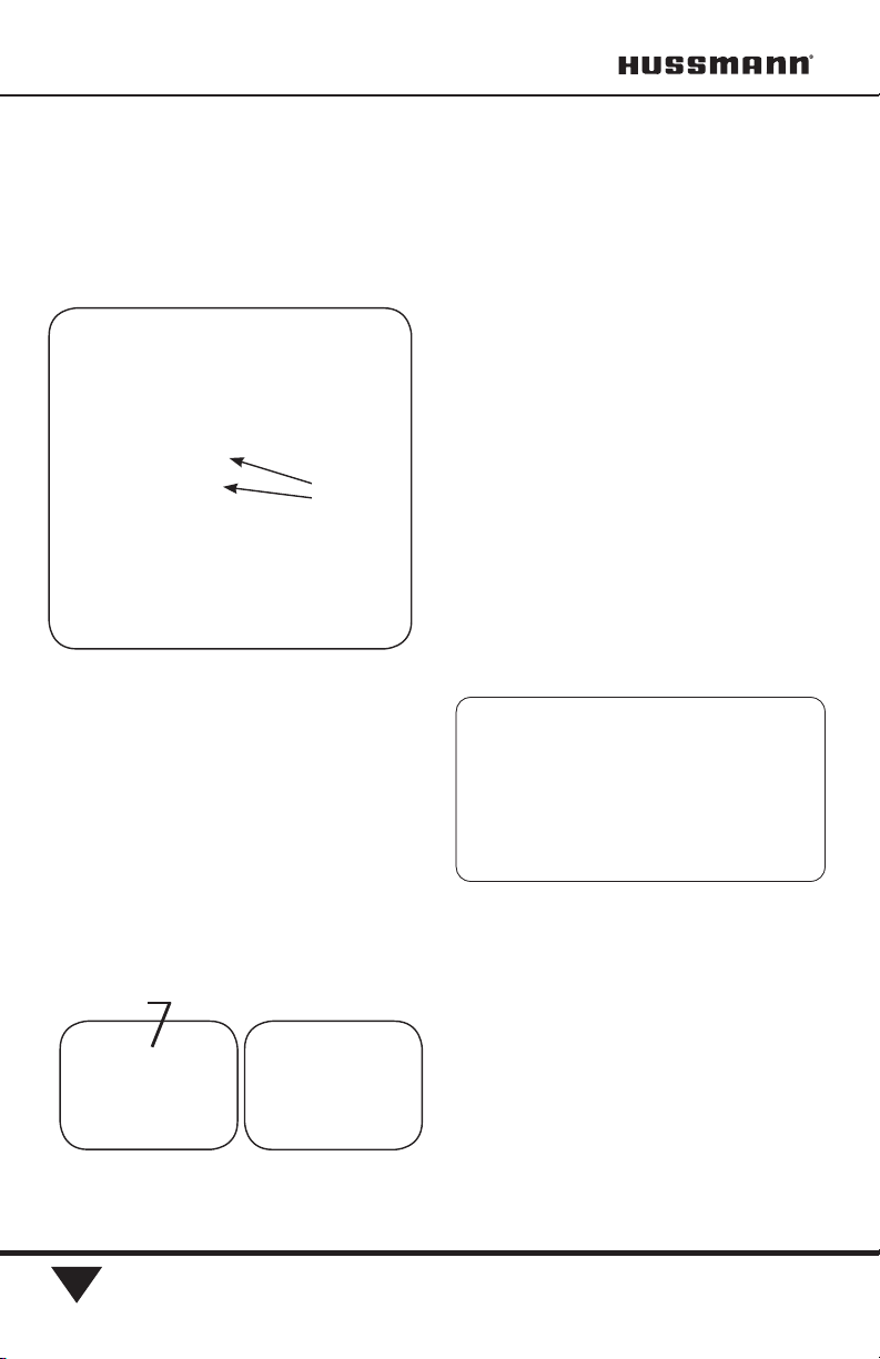
1. Check the doors for proper closing torque:
Test 1: Open door 90 degrees and close it manually.
Make sure the door opens and closes without binding
Test 2: Open door 90 degrees and release it. The door
should close on its own
Test 3: Open door more than 3” but less than 6” and
release it. The door should close on its own.
Torque adjustment, if needed, should be performed
“one click” at a time. A “zero” torque
door should not require more than 4 clicks.
If the torque cam and hinge socket are severely rusted,
both components should be replaced. A severely rusted
cam / socket assembly will not hold torque. Rust on
the cam socket assembly is usually caused by one of the
following:
• High humidity conditions > ASHRAE Type I
• Cycling of the frame heaters
Note 1: A rusted torque cam / socket assembly can
cause excessive wear on the torque rod’s spacer and
sleeve bearing. The result is a door that can “seat” far-
ther down the rod assembly to the point that it causes
binding at the hold open bracket. It can also cause the
top hinge pin’s sleeve bearing to deform. If the door is
seated too far down the torque rod assembly, it most
likely damaged the top hinge pin sleeve bearing. If the
pin is not bent, replacing the pin’s nylon sleeve bearing
will be sufficient. Although the torque rod assembly’s
sleeve bearing and spacer are replaceable, we recom-
mend that a severely rusted torque rod assembly be
replaced.
2) Inspect door gaskets:
• Check for tearing gaskets
• Make sure the gasket’s dart is properly seated into
the door’s gasket groove.
3) Inspect the top hinge assembly for exces-
sive movement at the top hinge socket.
• By design, the door will have a small, but discern-
ible amount of movement at the top hinge pin / hinge
plate socket joint. If excessive movement is detected,
the hinge pin assembly should be inspected to ensure
that the hinge pin is not bent (refer to note #1)
4) Inspect hold open bracket:
• Open the door to the “hold open” engagement
position. The “hold open” bracket should retain
the door.
• If the bracket fails to retain the door, replace the
bracket and the shoulder screw.
5) If a door passes the three “open / close”
tests, and there is no excessive movement at
the top hinge pin, then it is highly unlikely
that any components require replacement.

U.S. & Canada 1-800-922-1919 • Mexico 1-800-890-2900 • WWW.HUSSMANN.COM
P/N 0425683_M
4
Key Inspection Points
Top Hinge Pin
&
Hold Open Bracket
Torque Rod
Assembly
Top Hinge Plate Hold Open Bracket

Hussmann Corporation • Bridgeton, Missouri 63044-2483 U.S.A.
Innovator Door Installation and Service Instruction P/N 0425683_M
5
If the hinge pin sleeve bearing is damaged or worn,
the hinge pin will not move freely inside the door’s pin
sleeve. Push down on the hinge pin, if the pin “sticks”
and does not “return”, the sleeve bearing will need
to be replaced. The photos below are examples of a
deformed sleeve bearing; however, the root cause was
excessive wear on the torque rods spacer and sleeve
bearing. The damage to the torque rod components
was caused by external factors (prolonged high humid-
ity or cycling the frame’s anti sweat heaters). The best
solution is to replace the torque rod assembly and
hinge pin sleeve bearing, however, if the external factors
are not addressed, this will be become a recurring
problem.
Below is an example of a damaged sleeve bearing. The
compromised torque rod components caused the door
to “seat” below its designed parameter. Because the
door has essentially been lowered, it causes the sleeve
bearing to deform. In scenario above, we recommend
replacing the torque rod assembly; however, the hinge
pin sleeve bearing is a replaceable component.
Push down on
hinge and make
sure that the
spring returns it
to the extended
period.
If the pin
“sticks” at
its depressed
position, the
sleeve bearing
will need to be
replaced.
Damaged Sleeve Bearing

U.S. & Canada 1-800-922-1919 • Mexico 1-800-890-2900 • WWW.HUSSMANN.COM
P/N 0425683_M
6
Below is a 5-year-old torque rod that does NOT
require maintenance. All components are intact
and performing properly.
Below is a rod that has operated for prolonged
periods of time in > Type-1 conditions. This rod
assembly should be replaced.
Sleeve bearing and spacer are in excellent
condition.
Sleeve bearing and spacer have been
compromised.

Hussmann Corporation • Bridgeton, Missouri 63044-2483 U.S.A.
Innovator Door Installation and Service Instruction P/N 0425683_M
7
REPLACING DOORS
1. Loosen torque on door before removing the door.
Wedge a screwdriver between the bottom of the door
and the hinge socket, then lift the door up. This will
lift the bottom hinge pin up and out of the bottom
hinge socket. Hold the hinge pin with a 1/2 in. (13
mm) open end wrench to keep it from spinning out and
stripping the socket. See Figure 3.
Lift up
Screwdriver
Figure 3. Loosening Torque on the Door
— LOCK OUT / TAG OUT —
To avoid serious injury or death from
electrical shock, always disconnect the
electrical power at the main disconnect
when servicing or replacing any electri-
cal component. This includes, but is not
limited to, such items as doors, lights,
fans, heaters, and thermostats.

U.S. & Canada 1-800-922-1919 • Mexico 1-800-890-2900 • WWW.HUSSMANN.COM
P/N 0425683_M
8
2. Unscrew the two #6 Phillips screws that hold the
black plug into the side of the door as shown in Figure 4.
Remove the plug from the door.
3. Grasp the strain relief just below the cord and pull
until the heater terminal plug comes out. See Figure 5.
Note that the left end door must be opened more than
90 degrees to access the screws.
4. Use a flat blade screwdriver as shown in Figure 6
to lift the door retainer over the shoulder screw.
5. Push down the top hinge pin until it clears the
top socket using a flat blade screwdriver as shown in
Figure 7. With finger, hold the hinge pin in the door
to keep it from popping out. Tape may be used to
temporarily hold the hinge pin once door is removed.
Figure 4. Removing Screws to Plug
Figure 5.
Removing the Heater Terminal Plug
Remove Screws
Figure 6. Removing the Door Retainer
Door Retainer
Figure 7.
Removing the Door from the Top Hinge Pin
Top
Hinge
Pin

Hussmann Corporation • Bridgeton, Missouri 63044-2483 U.S.A.
Innovator Door Installation and Service Instruction P/N 0425683_M
9
6. Rock the door out and pull the bottom hinge pin
out from the bottom socket.
7. Install the new door in reverse order.
8. Adjust the torque on the new door. If needed,
adjust sag.
INNOVATOR DOOR HINGE
REPLACEMENT
The following provides supplemental information for
the replacement of a worn hinge pin. In addition to the
hinge pin, it is recommend that the following parts be
replaced.
*Note: If a hinge pin is bent or worn because of
improper shimming, the addition of a nylon spacer
(item 7), attached to the door’s torque rod, may be
required.
In order to address a worn hinge pin, it is necessary to
remove the door from the frame.
Note: The new hinge pin supplied with this replace-
ment kit is longer than the existing hinge pin. These
were designed to be backward compatible.
Tips for replacing the hinge pin and related components:
• Always replace components 1 through 6.
• Torque all retaining screws to 100 in-lbs.
• After removing the pin and spring, clean out any
debris (nylon or metal shavings) that may
be remaining in the door’s “hinge pin /spring” socket.
• Make sure the hinge pin bushing (4551267) is
installed onto the hinge pin (0453783)
• If the hinge pin is bent, it’s because the pin is rotat-
ing on its shaft instead of the top bell. This is most
likely caused by improper shimming. To correct the
issue, order the torque rod spacer (item 7) along with parts
1 through 6.
REPLACING MAGNETIC GASKET
Carefully remove the old gasket from the groove in the
back of the door, Figure 9.
The new gasket will be easier to work with if it is at
ambient temperature. Begin by lubricating the new
gasket with a mild soap and water solution.
Gasket
1. Top Hinge Plate 0543783
2. Top Hinge Plate Bushing 4551267
3. Top Hinge Spring (long) 1900391
4. Top Hinge Plate Socket (black) 4550103
5. Top Hinge Plate Socket (silver) 4550103
6. Torque Rod Spacer (*see note) 4551465
7. Socket Retainer Screw 0539743

U.S. & Canada 1-800-922-1919 • Mexico 1-800-890-2900 • WWW.HUSSMANN.COM
P/N 0425683_M
10
Work from the corners to the centers of each side, top
and bottom. Carefully push the new gasket into the
groove at each corner, refer to Figure 10(A). Then,
push the gasket into the channel at the center of the top,
bottom and each side, Figure 10(B). Avoid stretching
the gasket.
Sub-divide remaining areas and push the gasket in at
those points, Figure 10(C).
Sub-divide once again and repeat pushing the gasket
in until all of the gasket is evenly seated in the groove,
Figure 10(D).
Use a soft cloth or paper towels to dry the gasket
before closing door on clean door frame.
RESTORING GASKET SEAL
Occasionally, a crimped or damaged gasket can cause
gaps in the seal (Figure 11), leading to frost formation
on the doors. Use this procedure to close gaps and end
frost formation on doors.
Locate Gaps
Normally, interior case lighting will provide enough
light to see gaps. In some cases, the only way to see
gaps is to provide a backlight as shown in Figure
12(A). Backlight the door mullion and look for places
the light shines between the door and gasket, Figure
12(B).
Corners First Middle of Door
Sub-divide Middle Locations Sub-divide again
Figure 10.
Sequence for Installing New Gasket
(A) (B)
(C) (D)
Figure 11.
Improperly Installed or Damaged Gasket
Figure 12. Back-Lighting Gaps in Gasket
Back-Light
Gap
(B)
(A)
Gap

Hussmann Corporation • Bridgeton, Missouri 63044-2483 U.S.A.
Innovator Door Installation and Service Instruction P/N 0425683_M
11
Heat the Gasket
Make sure the door is closed. Beginning
at the top of the gap, use a heat gun or
electric hair dryer (1500-1600 watt) to
heat the gasket with a constant up and
down motion.
IMPORTANT: If a gap runs the entire
length of the door, heat the area 4 in. (100
mm) above and 8 in. (200 mm) below the
top-most point where the gap starts and
work in 12 in. (300 mm) increments.
If the gasket becomes shiny, remove
heat immediately as this is an indi-
cation that the gasket is near the
melting point.
If possible, direct the hot air onto the gas-
ket and also through the gap between the
gasket and mullion. This will help to heat
both sides of the gasket. Refer to Figure
13(A) and (B).
As the gasket softens and becomes pliable,
the magnet in the gasket should pull it
across the gap. As the gap closes, move
heat down to create a zippering effect as
shown in Figure 14.
If the gasket is not pulled across the gap
by the magnet, reach around the mullion
(from the inside) and pull the gasket skirt
toward the mullion.
Gap
Back-Light
Direct the hot air through the gap
between the gasket and mullion.
Back-Light
Remember to use a con-
stant up and down motion
when applying heat.
Figure 13. Applying Heat to Gasket
(A)
(B)
Figure 14. Zipper Effect
(A)
(B)

U.S. & Canada 1-800-922-1919 • Mexico 1-800-890-2900 • WWW.HUSSMANN.COM
P/N 0425683_M
12
As shown in Figure 15, this can also be accomplished by
pushing the magnet across the gap from the outside with a
pencil or other non-heat conducting material.
On doors where the gap is against an end, top, or
bottom mullion, this process can still be done; how-
ever, the heat will need to be directed between the lip
of the mullion and the edge of the door. It will work
in the same fashion but the back-light shining through
and showing on the mullion will have to be a guide as
to the position of the gasket.
Cool the Gasket
Once the gap is closed, remove the heat and allow the
gasket to cool, undisturbed, for 3 to 5 minutes. As the
gasket cools, it will set permanently in this new shape.
Once the gasket is cool to the touch, open the and close
the door. Verify that the gasket seals. If not, repeat the
process. If the gasket rolls it must be replaced.
Use a soft cloth or paper towels, and a mild soap and
water solution to thoroughly clean the gasket. Dry the
gasket completely with a fresh cloth or paper towels
before closing the door on a clean door frame.
DOOR HANDLE REPLACEMENT
Carefully pull the
magnetic gasket out of
the groove nearest the
handle to expose the
mounting screws as shown
in Figure 16. Remove the
screws and replace the
handle. After reinstalling
screws, carefully push
gasket back into groove.
If needed, use a mild
soap and water solution
to lubricate the gasket.
Clean and dry the gasket
to complete the door han-
dle replacement.
FRAME HEATER REPLACEMENT
Always turn off power to the case before working on
any electrical components. The old wireway covers
must be removed to access the door frame heaters.
Begin by inserting a putty knife into the groove
between the wireway cover and fiberglass frame, about
an inch (25 mm) away from joints in the frame as
shown in Figure 17(A). Carefully begin to pry off the
cover.
As shown in Figure 17(B), use a second putty knife
or flat head screwdriver to hold up the cover. Pry the
remainder of the section up, using putty knife only,
until the entire cover is off and the frame heater inside
the door frame is exposed.
Mounting Screws
Figure 15. Pulling Gasket Into Place
With a Pencil
Figure 16. Replacing Door Handle

Hussmann Corporation • Bridgeton, Missouri 63044-2483 U.S.A.
Innovator Door Installation and Service Instruction P/N 0425683_M
13
Door frame heaters shown in Figure 18 may now be
replaced.
During installation, the white portion of the heater
should not come in contact with itself. The heater
should be installed so that only one white portion of
the wire enters the raceway. The other portion entering
the raceway will be the black lead wire.
Once the heater wire is connected, check resistance
(ohm reading) before replacing wireway covers. This
will ensure that heater wire was not broken during
installation. Wiring diagrams are shown in Figure 19.
After covers are reinstalled, turn power on and verify
that heaters are working properly.
— LOCK OUT / TAG OUT —
To avoid serious injury or death from electri-
cal shock, always disconnect the electrical
power at the main disconnect when servicing
or replacing any electrical component. This
includes, but is not limited to, such items as
doors, lights, fans, heaters, and thermostats.
Figure 17. Removing Door Wireway Covers
(B)
(A)
Figure 18. Replacing Door Frame Heaters

U.S. & Canada 1-800-922-1919 • Mexico 1-800-890-2900 • WWW.HUSSMANN.COM
P/N 0425683_M
14
DASH Controller
The Door Anti Sweat Heater (DASH) controller is
designed for conservation of energy by reducing power
consumption of the glass door frame assemblies.
The control consists of three components: a control
module located in the raceway, a combination tempera-
ture and %RH sensor mounted in the door mullion
and an interconnecting cable. All three components are
factory installed in the frame assembly.
The glass anti-condensate heaters are under the control
of a microprocessor, which eliminates operator
adjustment and guarantees maximum energy savings.
The sensor detects product loading as well as peak
shopping to optimize clearing time.
The control switches a maximum load of 5 amps which
allows the control to be applied to one to five door
frame assemblies. Each is equipped with its own con-
trol/sensor.
Heater
Leads
Leads Terminal Block
Typical Low Temperature Frames
Terminal Block
Heater Harnesses
Typical Medium Temperature Frames
Frame
Heater
Figure 19. Heater Harness Wiring Diagram
Control Module
Sensor
Door Heater Control Components
Operating Ambient: –20 to +100 deg F
Input Voltage: 100 to 250 VAC

Hussmann Corporation • Bridgeton, Missouri 63044-2483 U.S.A.
Innovator Door Installation and Service Instruction P/N 0425683_M
15
Sequence of Operation
Normal Operation
1. Power up.
2. Heater output on for 10 sec.
3. Read Temperature and %RH.
4. Calculate % On-Time of 10 Second period.
5. Output calculated duty cycle over 10 sec-
onds.
6. Repeat Steps 3 through 5.
Failure Mode Operation
Lost or Erratic Sensor Readings
Action: 100% On
95%RH <Sensor Values <10%RH
Action: 100% On
85°F<Sensor Values < 40°F
Action: 100% On
1. Remove the mullion cover between the pair of doors where
the sensor is located.
Sensor Board
2. A plastic rivet holds the sensor board securely through a
hole in one end.
Harness
3. The harness has connectors at each end. Push one end of
the harness onto the sensor board.
4. Position the sensor board gasket around the board and
over the harness. Route lamp wiring around the gasket.
5. Important: Verify the sensor board perimeter is com-
pletely sealed. Use electrical tape to hold wiring in position
at the center of the mullion. This will avoid damage when
replacing the cover.
Sensor Control Box
6. The control box is mounted to the ballast tray with #8 x
3/8 sheet metal screws.
7. Connect the sensor harness to the control box.
Door Heater Harness
8. Connect the insulated male connectors of the door heater
harness to the sensor control box. Pins are marked.
Power Connection
9. Connect the insulated male connectors for line power and
neutral to the sensor control box. Pins are marked.
Finish
10. Check that all wiring is secure within the mullion and
frame, then replace covers.
11. Restore power.
12. Verify controller is cycling the anti-condensate door
heaters.
120V Power Neutral
Frame A.S. Heaters
Calentadores A.C. de marco
Door A.S. Heaters
Calentadores A.C. de puerta
Control
Box
Humidity
Sensor
Wiring Diagram for Controller
Board Correctly Secured
Rivet
Add Tape
RefeR to Hussmann document P/n 2402799 foR moRe detail.

U.S. & Canada 1-800-922-1919 • Mexico 1-800-890-2900 • WWW.HUSSMANN.COM
P/N 0425683_M
16
ECOSHINE II & ECOSHINE II PLUS
LED FIXTURE
EcoShine II LED (light emitting diode) lights work
well for dimming or on/off operation using an occu-
pancy sensor (optional kits). They can be turned
on and off in a cold environment with no warm-up
time and no negative impact on lamp life.
Hussmann EcoShine II LED light fixtures normally
perform for up to 50,000 hours. That is 5.7 years of
continuous, 24 hour operation. Light
Switch
— LOCK OUT / TAG OUT —
To avoid serious injury or death from electri-
cal shock, always disconnect the electrical
power at the main disconnect when servicing
or replacing any electrical component. This
includes, but is not limited to, such items as
doors, lights, fans, heaters, and thermostats.
27mm
42mm
27mm
55mm
27mm
42mm
27mm
55mm
27mm
42mm
27mm
55mm
Center LED(s)
(ES II LEDS)
(ES II LEDS)
(ES II LEDS)
27mm
42mm
27mm
55mm
27mm
42mm
27mm
55mm
(ES II LEDS)
(ES II LEDS)
27mm
42mm
27mm
55mm
(ES II LEDS)
Left End
Right End
LED Power Supply Location
(Standard RL Merchandiser Shown)
2 LEDs
Other manuals for Innovator
1
This manual suits for next models
2
Table of contents
Other Hussmann Refrigerator manuals

Hussmann
Hussmann Super Plus User manual

Hussmann
Hussmann Proto-Aire User manual

Hussmann
Hussmann DD5X5FRW User manual

Hussmann
Hussmann MZ3-S Original operating instructions

Hussmann
Hussmann Innovator Manual

Hussmann
Hussmann Chino RDI-27 Original operating instructions

Hussmann
Hussmann GIM Quick guide

Hussmann
Hussmann DBP-01 Operating instructions

Hussmann
Hussmann CR3-HV-SWD User manual

Hussmann
Hussmann DDSS-4MC User manual