Hussmann Chino RDI-27 Original operating instructions

RDI
REFRIGERATED DROP IN DISPLAY
INSTALLATION & OPERATION GUIDE
/CHINO
RDI
REFRIGERATED DROP IN DISPLAY REV. 0913
Installation
& Operation
Manual

2
/CHINO
A publication of
Hussmann®Chino
13770 Ramona Avenue • Chino, California 91710
(909) 628-8942 FAX
(909) 590-4910
(800) 395-9229
Keep this booklet with the case at all times for future reference.
THIS BOOKLET CONTAINS INFORMATION ON:
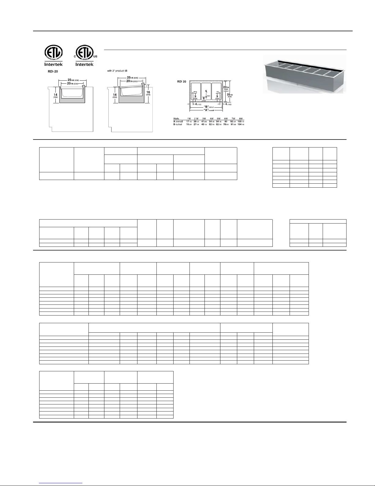
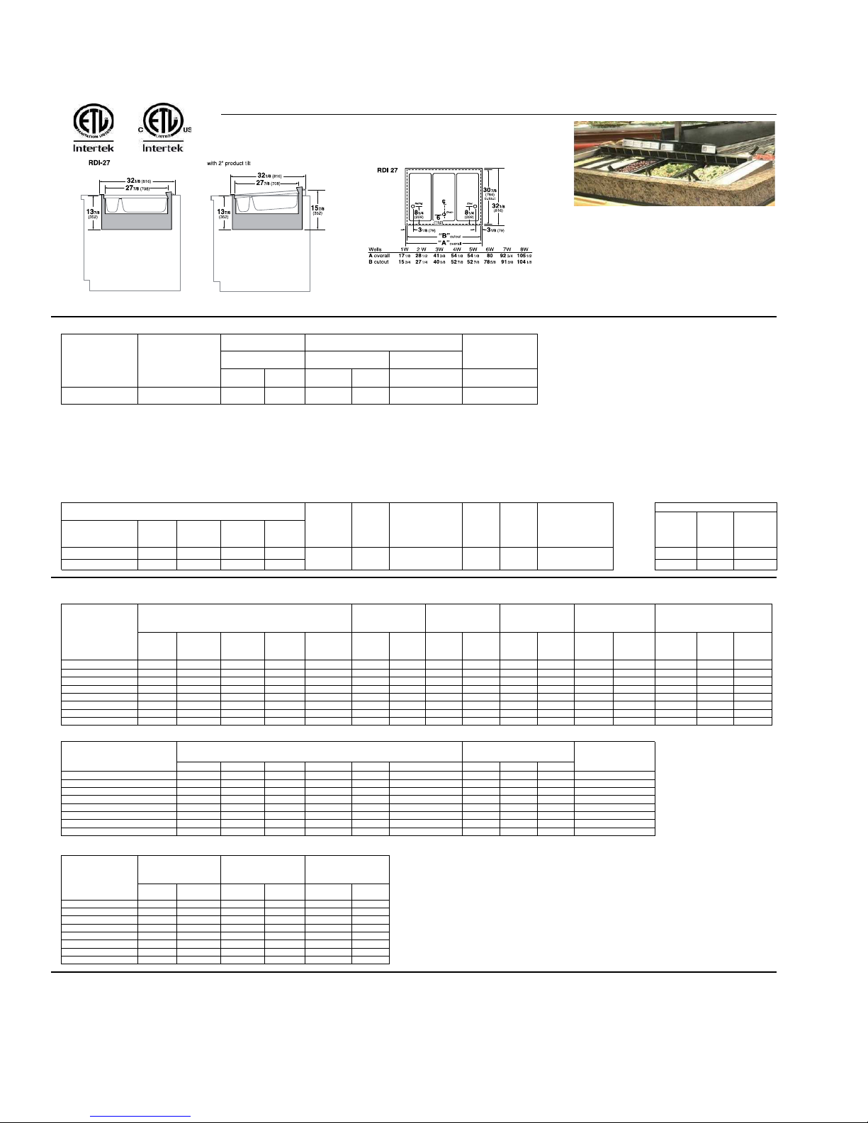
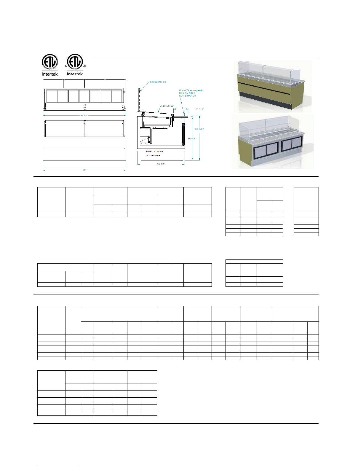
RDI: Refrigerated “Drop-In” display designed for installation
into the top of dry service counters. Featuring upper and
lower air discharges allowing display of unwrapped food
whether in platters, bowls or pans.
SHIPPING DAMAGE
All equipment should be thoroughly examined for shipping
damage before and during unloading.
This equipment has been carefully inspected at our factory
and the carrier has assumed responsibility for safe arrival.
If damaged, either apparent or concealed, claim must be
made to the carrier.
APPARENT LOSS OR DAMAGE
If there is an obvious loss or damage, it must be noted on
the freight bill or express receipt and signed by the carrier’s
agent; otherwise, carrier may refuse claim. The carrier will
supply necessary claim forms.
CONCEALED LOSS OR DAMAGE
When loss or damage is not apparent until after equipment
is uncrated, a claim for concealed damage is made. Make
request in writing to carrier for inspection within 15 days,
and retain all packaging. The carrier will supply inspection
report and required claim forms.
SHORTAGES
Check your shipment for any possible shortages of
material. If a shortage should exist and is found to be the
responsibility of Hussmann Chino, notify Hussmann Chino.
If such a shortage involves the carrier, notify the carrier
immediately, and request an inspection. Hussmann Chino
will acknowledge shortages within ten days from receipt
of equipment.
HUSSMANN CHINO PRODUCT CONTROL
The serial number and shipping date of all equipment
has been recorded in Hussmann’s files for warranty and
replacement part purposes. All correspondence pertaining
to warranty or parts ordering must include the serial number
of each piece of equipment involved, in order to provide
the customer with the correct parts.
General Instructions
Table of Contents
General Instructions.....................................................2
Cut & Plan Views ..........................................................3
Opening Dimensions....................................................4
Installation.....................................................................4
Location ..................................................................................... 4
Uncrating the Stand................................................................... 4
Exterior Loading......................................................................... 4
Leveling ..................................................................................... 4
Plumbing .......................................................................5
Waste Outlet and P-TRAP......................................................... 5
Refrigeration .................................................................6
Refrigerant Type ........................................................................ 6
Piping......................................................................................... 6
Refrigeration Lines .................................................................... 6
Control Settings ......................................................................... 6
Evaporator Fans ........................................................................ 6
Access to TX Valves and Drain Lines........................................ 6
Thermostatic Expansion Valve Location.................................... 6
Expansion Valve Adjustment ..................................................... 6
Measuring the Operating Superheat.......................................... 6
T-STAT Location ........................................................................ 6
Spec Sheets ..................................................................7
Electrical......................................................................10
Wiring Color Code ................................................................... 10
Electrical Circuit Identification.................................................. 10
Field Wiring and Serial Plate Amperage.................................. 10
User Information.........................................................10
Stocking................................................................................... 10
Important Steps ....................................................................... 11
Case Cleaning ......................................................................... 11
Maintenance................................................................ 11
Evaporator Fans ...................................................................... 11
Copper Coils ............................................................................ 11
Tips and Troubleshooting ........................................................ 11
Stainless Steel Cleaning and Care.......................................... 12
Electrical Wiring Diagrams........................................14
Wiring Diagrams ......................................................... 15
Appendices .................................................................25
Appendix A. - Temperature Guidelines .................................... 25
Appendix B. - Application Recommendations.......................... 25
Appendix C. - Field Recommendations ................................... 25
Appendix D. - Recommendations to user................................ 26
Controller Parameters................................................28
Controller Instructions...............................................30
This equipment is to be installed
to comply with the applicable
NEC, Federal, State , and Local
Plumbing and Construction
Code ha ving jurisdiction.
ATTENTION
INSTALLER

3
Cut & Plan Views
6
1
/2"
Bottom
Discharge
(for Pans)
Fan
Full Pan
12" X 20" X 6"
25 1/8
" Flange (
23 7/8
" single well)
23 3/4
" cut out (
22 1/2
" single well)
20
"
13 7/8"
RDI-20
Self-Service – 2-10 wells
Scale = 1"
Top Discharge
(for Open Well)
20" PAN
+ 1/3 PAN
14"
16"
BENEATH
COUNTER
RDI 27
Refrigerated Drop-In
Self Service Case
Shown with Optional 2" Tilt
Scale = 1/2"
30 5/8" Cut Out
RDI
BACK TO BACK 20"
Refrigerated Self Service Case
Scale = 3/8"
15 1/2"
Below
Counter
50" Cut Out
51 1/2" Trim
12 X 20
PAN
6
1
/2"
Bottom
Discharge
(for Pans)
30 3/4
" cut out (
29 1/2
" single well)
RDI-27
Self-Service – 2-10 Wells
Scale = 1"
Fan
13 7/8
"
32 1/8
" Flange (
30 7/8
" single well)
Full Pan
12" X 20" X 6"
1/3rd
pan
27
"
Top
Discharge
(for Open
Well)
14"
30 5/8" Cut Out
RDI 27
Refrigerated Drop-In
Self Service Case
Shown with Optional 4" Tilt
Scale = 1/2"
20" PAN
+ 1/3 PAN
18"
BENEATH
COUNTER
32 1/8" Trim
50" Cut Out
RDI BACK TO BACK 20"
Refrigerated Self Service Case
Shown with Optional 2" Tilted Pan
Scale = 3/8"
51 1/2" Trim
15 1/2"
Below
Counter
12X 20
PAN
2" Tilt
RDI BOWL OPTION
Self-Service
14"
Fan
6
1
/2"
281/2"
RDI-27
2-Well
Scale = 1/4"
Full Pan
(12" x 20")
Third Pan
(6" x 12")
RDI-27
4-Well
Scale = 1/4"
541/8"
415/16"
RDI-27
3-Well
Scale = 1/4"
Three sample modules are sho wn abo ve. The RDI has been
engineered for lengths from 1-Well up to 11-Wells in one full pan or
one pan & 1/3rd design.

4
Installation
Well Dimensions
20"
Front to Back 1 well 2 or more wells
!ange 23 7/8" 25 1/8"
cutout 22 1/2" 23 3/4"
Side to Side length 1 wells 2 wells 3 wells 4 wells 5 wells 6 wells 7 wells 8 wells 9 wells 10 wells
!ange 17 1/8" 28 3/4" 41 1/2" 54 3/8" 67 1/8" 80" 92 3/4" 105 1/2" 118 3/8" 131 1/8"
cutout 15 3/4" 27 3/8" 40 1/8" 53" 65 3/4" 78 5/8" 91 3/8" 104 1/8" 117" 129 3/4"
27"
Front to Back 1 well 2 or more wells
!ange 30 7/8" 32 1/8"
cutout 29 1/2" 30 3/4"
Side to Side length 1 wells 2 wells 3 wells 4 wells 5 wells 6 wells 7 wells 8 wells 9 wells 10 wells
!ange 17 1/8" 28 3/4" 41 1/2" 54 3/8" 67 1/8" 80" 92 3/4" 105 1/2" 118 3/8" 131 1/8"
cutout 15 3/4" 27 3/8" 40 1/8" 53" 65 3/4" 78 5/8" 91 3/8" 104 1/8" 117" 129 3/4"
The RDI comes in various lengths and should be installed
in a proper and uniform manner. The following guidelines
will help ensure proper installation.
1. Case location should be near a !oor sink or waste
outlet - with electrical and refrigeration access
usually under the case.
2. All plumbing should conform to local codes.
3. When the RDI is to be installed in an existing #xture
or in a supplied #xture, the RDI and the new or
existing #xture should be leveled front to back and
side to side.
4. The electrical junction box is located under the RDI
which is where the electrical is terminated by the
manufacturer. The junction box is a standard 2x4
box with knock-outs and cover.
5. The refrigeration is also stubbed down under the
case for connection to liquid and suction lines from
the remote RDI case.
6. In cases where more than one RDI are installed, run
drains separately to the sink or drain outlet.
7. For RDI units installed in an existing table, the lip
on the unit should be sealed with a NSF approved
sealant and all Phillips screws slots should be
sealed with same.
8. The RDI should be dropped in the existing table
oriented with the discharge air blowing from the front
to the back of the #xture, the front is identi#able by
the adjustable top air discharge control pins.
9. A thermostat and solenoid mounted in the suction
line is recommended for temperature control and
defrost.
10. Set defrost per case specs section of this book.
Location
The refrigerated merchandisers have been designed
for use only in air conditioned stores where temperature
and humidity are maintained at or below 75°F and 55%
relative humidity. DO NOT allow air conditioning, electric
fans, ovens, open doors or windows (etc.) to create air
currents around the merchandiser, as this will impair its
correct operation.
Product temperature should always be maintained at a
constant and proper temperature. This means that from the
time the product is received, through storage, preparation
and display, the temperature of the product must be
controlled to maximize life of the product.
Uncrating the Stand
Place the #xture as close to its permanent position as
possible. Remove the top of the crate. Detach the walls
from each other and remove from the skid. Unbolt the case
from the skid. The #xture can now be lifted off the crate
skid. Lift only at base of stand!
Exterior Loading
These models have not been structurally designed to
support excessive external loading. Do not walk on their
tops; This could cause serious personal injury and damage
to the #xture.
Leveling
IMPORTANT! IT IS IMPERATIVE THAT THE RDI AND
THE FIXTURE THAT THE RDI IS INSTALLED IN,
BE LEVELED FROM FRONT TO BACK AND SIDE
TO SIDE PRIOR TO JOINING. A LEVEL CASE IS
NECESSARY TO INSURE PROPER OPERATION,
WATER DRAINAGE.
NOTE: A. To avoid removing concrete flooring, begin lineup
leveling from the highest point of the store floor.
B. When wedges are involved in a lineup, set them first.
Opening Dimensions

5
All cases were leveled and joined prior to shipment to
insure the closest possible •t when cases are joined in
the •eld. When joining, use a carpenters level and shim
legs accordingly. Case must be raised correctly, under legs
where support is best, to prevent damage to case.
1. Check level of •oor where cases are to be set.
Determine the highest point of the •oor; cases will
be set off this point.
2. Level and set the •rst case, carefully guiding the
electrical, refrigeration and drain lines through the
parent case. Case must be raised under legs where
support is best to prevent damage to case. Internal
bracing may be removed at this time.
3. Apply liberal bead of case joint sealant (NSF
Approved) to cover dotted area shown below.
DO NOT USE PERMAGUM!
Proper case-joint sealing is extremely
important to prevent water leaks!
It is the contractor’s responsibility to install
case(s) according to local construction and
health codes.
Installation (Cont’d)
Plumbing
Waste Outlet and P-TRAP
The waste outlet is located at the left hand end of these
•xtures allowing drip piping to be run under the •xture
lengthwise.
A 1 1/2” P-TRAP and threaded adapter are supplied with
each •xture. The P-TRAP must be installed to prevent air
leakage and insect entrance into the •xture.
Installing Condensate Drain
Poorly or improperly installed condensate drains can
seriously interfere with the operation of this refrigerator, and
result in costly maintenance and product losses. Please
follow the recommendations listed below when installing
condensate drains to insure a proper installation:
1. Never use pipe for condensate drains smaller
than the nominal diameter of the pipe or P-TRAP
supplied with the case.
2. When connecting condensate drains, the P-TRAP
must be used as part of the condensate drain
to prevent air leakage or insect entrance. Store
plumbing system •oor drains should be at least 14"
off the center of the case to allow use of the P-TRAP
pipe section. Never use two water seals in series in
any one line. Double P-TRAPS in series will cause a
lock and prevent draining.
3. Always provide as much down hill slope (“fall”) as
possible; 1/8" per foot is the preferred minimum.
PVC pipe, when used, must be supported to
maintain the 1/8" pitch and to prevent warping.
4. Avoid long runs of condensate drains. Long runs
make it impossible to provide the “fall” necessary for
good drainage.
5. Provide a suitable air break between the •ood rim of
the •oor drain and outlet of condensate drain. 1" is
ideal.
6. Prevent condensate drains from freezing:
a. Do not install condensate drains in contact with
non-insulated suction lines. Suction lines should
be insulated with a nonabsorbent insulation
material such as Armstrong’s Arma•ex.
b. Where condensate drains are located in dead
air spaces (between refrigerators or between a
refrigerator and a wall), provide means to prevent
freezing. The water seal should be insulated to
prevent condensation.

6
Refrigeration
Refrigerant Type
The standard refrigerant will be R-22 unless otherwise
specified on the customer order. Check the serial plate on
the case for information.
Piping
The refrigerant line outlets are piped through the rear
of the fixture at the left hand end when viewed from the
back. Insulate suction lines to prevent condensation from
dripping.
Refrigeration Lines
Liquid Suction
3/8” O.D. 5/8” O.D.
NOTE: The standard coil is piped at 5/8" (suction); however,
the store tie-in may vary depending on the number of
coils and the draw the case has. Depending on the case
setup, the connecting point in the store may be
5/8", 7/8", or 11/8". Refer to the particular case you are
hooking up.
Refrigerant lines should be sized as shown on the
refrigeration legend furnished by the store.
Install P-TRAPS (oil traps) at the base of all suction line
vertical risers.
Pressure drop can rob the system of capacity. To keep the
pressure drop to a minimum, keep refrigerant line run as
short as possible, using the minimum number of elbows.
Where elbows are required, use long radius elbows only.
Control Settings
See RDI technical data sheet for the appropriate settings for
your merchandiser. Maintain these parameters to achieve
near constant product temperatures. Product temperature
should first be measured in the morning, after having been
refrigerated overnight. For all multiplexing, defrost should
be time terminated. Defrost length and frequency should be
as directed in the RDI technical data sheet. The number of
defrosts per day should never change. The duration of the
defrost cycle may be adjusted to meet conditions present
at your location
Evaporator Fans
The evaporator fans are located at the center front of these
merchandisers directly beneath the display pans.
FORACCESS TO THE FANS: Remove the right hand deck
pan as viewed from the front of the case.
Access to TX Valves and Drain Lines
MECHANICAL - Remove product from end of case.
Remove product racks. Remove refrigeration and drain
access panels (labeled). TX valve (mechanical only) and
drain are located under each access panel at end of the
case.
ELECTRONIC - The Electronic Expansion valve master
and slave cylinder(s) are located within the electrical access
panel(s).
Electronic Expansion Valve (Optional)
A wide variety of electronic expansion valves and case
controllers can be utilized. Please refer to EEV and
controller manufacturers information sheet. Sensors for
electronic expansion valves will be installed on the coil inlet,
coil outlet, and in the discharge air. (Some supermarkets
require a 4th sensor in the return air). Case controllers will
be located in the electrical raceway or under the case.
Thermostatic Expansion Valve Location
This device is located on the same side as the refrigeration
stub. A Sporlan balanced port expansion valve model
is furnished as standard equipment, unless otherwise
specified by customer.
Expansion Valve Adjustment
Expansion valves must be adjusted to fully feed the
evaporator. Before attempting any adjustments, make
sure the evaporator is either clear or very lightly covered
with frost, and that the fixture is within 10°F of its expected
operating temperature.
Measuring the Operating Superheat
1. Determine the suction pressure with an accurate
pressure gauge at the evaporator outlet.
2. From a refrigerant pressure temperature chart,
determine the saturation temperature at the
observed suction pressure.
3. Measure the temperature of the suction gas at the
thermostatic remote bulb location.
4. Subtract the saturation temperature obtained in step
No. 2 from the temperature measured in step No. 3.
3. The difference is superheat.
5. Set the superheat for 5°F - 7°F.
T-STAT Location
T-STATS are located within the electrical raceway.

7
REFRIGERATED DROP-IN, REMOTE & SELF-CONTAINED REVISION DATE 08/22/18
HUSSMANN - RDI-20" (CHINO)
REFRIGERATION DATA:
1
0.2
0.3
0.0
2 0.2 0.6 0.3
3 0.3 0.9 0.5
4 0.5 1.2 0.7
5 0.6 1.5 0.9
6
0.8
1.8
1.3
**FRONT DISCHARGE AIR MEASURED INSIDE AIR CURTAIN HONEYCOMB
7
0.9
2.1
0.8
***REFRIGERATION NOTES:
1) USE DEW POINT FOR HIGH GLIDE REFRIGERANTS. CARE SHOULD BE TAKEN TO USE THE DEW POINT IN P/T TABLES
FOR MEASURING AND ADJUSTING SUPERHEAT. ADJUST EVAPORATOR PRESSURE AS NEEDED TO MAINTAIN THE
DISCHARGE AIR TEMPERATURE SHOWN.
2) REMOTE CASE RATING CONDITION IS NSF TYPE I, 75°F/55% RH
3) SELF CONTAINED CASE RATING CONDITION IS PER NSF 7.5.2
REFRIGERATION DATA CONTINUED:
REMOTE
32
29
-
-
1
1.125
SELF-CONTAINED
-
-
25
7
2
1.125
ELECTRICAL DATA:
STANDARD FANS, HEATERS, LED LIGHTS (115 VOLT)
1
1
0.8
20
N/A
N/A
N/A
N/A
N/A
N/A
N/A
N/A
N/A
N/A
N/A
2
1
0.8
20
N/A
N/A
N/A
N/A
N/A
N/A
N/A
N/A
N/A
N/A
N/A
3
2
1.6
40
N/A
N/A
N/A
N/A
N/A
N/A
N/A
N/A
N/A
N/A
N/A
4
2
1.6
40
N/A
N/A
N/A
N/A
N/A
N/A
N/A
N/A
N/A
N/A
N/A
5
3
2.3
60
N/A
N/A
N/A
N/A
N/A
N/A
N/A
N/A
N/A
N/A
N/A
6
3
2.3
60
N/A
N/A
N/A
N/A
N/A
N/A
N/A
N/A
N/A
N/A
N/A
7
4
3.1
80
N/A
N/A
N/A
N/A
N/A
N/A
N/A
N/A
N/A
N/A
N/A
8
5
3.9
100
N/A
N/A
N/A
N/A
N/A
N/A
N/A
N/A
N/A
N/A
N/A
CONDENSING UNIT AND EVAPORATIVE PANS
REFRIG.
Hz/Ph
VOLTS
RLA
AMPS
VOLTS
WATTS
R-404A
60 / 1
115
8
N/A
N/A
N/A
R-404A
60 / 1
115
8
N/A
N/A
N/A
R-404A
60 / 1
115
6
8.3
120
1000
R-404A
60 / 1
115
10.5
8.3
120
1000
R-404A
60 / 1
115
10.5
8.3
120
1000
R-404A
60 / 1
115
15
10.0
120
1200
R-404A
60 / 1
208
9
6.3
240
1500
R-404A
60 / 1
208
9.3
N/A
N/A
N/A
OPTIONAL HIGH OUTPUT LED LIGHTS (115 VOLT)
AMPS WATTS AMPS WATTS AMPS WATTS
1
N/A
N/A
N/A
N/A
N/A
N/A
2
N/A
N/A
N/A
N/A
N/A
N/A
3
N/A
N/A
N/A
N/A
N/A
N/A
4
N/A
N/A
N/A
N/A
N/A
N/A
5
N/A
N/A
N/A
N/A
N/A
N/A
6
N/A
N/A
N/A
N/A
N/A
N/A
7
N/A
N/A
N/A
N/A
N/A
N/A
8
N/A
N/A
N/A
N/A
N/A
N/A
WELLS
GPM PSI
DROP
EST. REFG.
CHRG.
(LBS)
2
3
4
5
1/2
20
1/4
1/3
1/2
15
20
20
30
20
MAX. H.O. LED
LOAD
NOM. HP
1/4
3/4
EVAPORATOR FANS
(4.7" AXIAL FANS)
CONDENSING UNIT
1
1
FUSE AMPS
15
15
7
8
1
AMPS
NUMBER OF
WELLS
NUMBER OF
WELLS
# OF
EVAP
FANS
AMPS WATTS
CANOPY
LIGHTS
H.O. LED
OPTIONAL
SHELF
6
NUMBER OF WELLS
USAGE
EST. REFG. CHRG.
R404A (LBS)
SELF-CONTAINED
AMPS WATTS AMPS
ELEC. THERMOSTAT / AIR SENSOR SETTINGS
SET
POINT
(°F)
DIFFER-
ENTIAL
(°F)
OFF TIME 20 6
DEFROST
TYPE
TIME
(MIN)
CUT
OUT
(ºF)
CUT IN
(ºF)
EVAPORATIVE PAN
AMPSWATTS
#
OUTLETS
VOLTS
VELOCITY
(FT/MIN)
NSF 7
END PANEL WIDTH KEY
END
PNL
WIDTH
(IN.)
TOTAL
ADDED
LENGTH (IN.)
CONVENIENCE OUTLETS
(OPTIONAL)
2.25
1.125
# OF END
PNLS
DEFROST WATER
(LBS/DAY/FT)
48 TBD 1.7
DRIP
TIME
TERM.
TEMP
(°F) COIL
ONLY
NUMBER OF WELLS CASE USAGE
CAPACITY ***
(BTU/HR/WELL)
TEMPERATURE (ºF)
DISCHARGE AIR
** (°F)
RATING
CONDITION EVAPORATOR
NSF 7
AHRI
1200 NSF 7
AHRI
1200 NSF 7
2.6
2.0
1.9
7.1
6.9
5.4
3.3
3.2
1, 2, 3, 4,
5, 6, 7, 8
COUNTER 840 NA 20 NA 29~31 325~375
AMPS
OPTIONAL LED
SHELF LIGHTS
MAX. LED LOAD
(W/ ALL OPTIONS)
ANTI-SWEAT
HEATERS
WATTSWATTS
DEFROST
FREQUENCY
(#/DAY)
CANOPY LIGHTS
LED
Spec Sheets

8
!"!!#$!
$%&&!
&
&&!! !
'
'
$!()
)!()
!$$)(
($$)(
)$'
'!$%
!!
""#$%!!&
)&))(!'
)&))(!'
$&))(!('$
&))(!!'$
&))(!!'$
$)&))(!!
&))('%($)!
&))('%$
!&&&
$
)
!
(
'
!!
(%
!)
$$
$
(
%
!
!$
'
$ ) ! ( '
')%*$$!*$!
$$&
'
(
!))))
&*
&""
!!!
+
"(
,+$&$$
+
!&&&&
-"&$
&&&!
+!""
(&""-"""&
)
!
!
$
""".).
'
"$
((
()'
'
(
$
!

! "#"
$%%$
!$!&'(
!$
)*+
)*+
)*+
)*+
)*+
)*+
)*+
!
"#
!
!
$
#
$
,, %
#&'(#&'
##"
#)
*+#,-.#&'
%*+#-.#&'
*
(/!0!
##
$!)(//)(//)
% #
)*+
)*+
)*+
)*+
)*+
)*+)*+

1010
User Information
Electrical
Wiring Color Code
CASE MUST BE GROUNDED
NOTE: Refer to label affixed to case to determine the actual
configuration as checked in the “TYPE INSTALLED”
boxes.
Electrical Circuit Identification
Standard lighting for all models will be full length !uorescent
lamps located on the front of the parent case.
The switch controlling the lights is located on the parent
case.
Field Wiring and Serial Plate Amperage
Field Wiring must be sized for component amperes printed
on the serial plate. Actual ampere draw may be less than
specified. Field wiring from the refrigeration control panel to
the merchandisers is required for refrigeration thermostats.
Case amperes are listed on the wiring diagram, but always
check the serial plate.
BEFORE SERVICING
ALWAYS DISCONNECT ELECTRICAL
POWER AT THE MAIN DISCONNECT
WHEN SERVICING OR REPLACING ANY
ELECTRICAL COMPONENT.
This includes (but not limited to) Fans, Heaters
Thermostats, and Lights.
Stocking
Improper temperature and lighting will cause serious
product loss. Discoloration, dehydration and spoilage
can be controlled with proper use of the equipment and
handling of product. Product temperature should always
be maintained at a constant and proper temperature.
This means that from the time the product is received,
through storage, preparation and display, the temperature
of the product must be controlled to maximize life of the
product. Hussmann cases were not designed to “heat up”
or “cool down” product-but rather to maintain an item’s
proper temperature for maximum shelf life. To achieve the
protection required always:
1. Minimize processing time to avoid damaging
temperature rise to the product. Product should be
at proper temperature.
2. Keep the air in and around the case area free
of foreign gasses and fumes or food will rapidly
deteriorate.
3. Maintain the display merchandisers temperature
controls as outlined in the refrigerator section of this
manual.
4. Do not place any product into these refrigerators
until all controls have been adjusted and they
are operating at the proper temperature. Allow
merchandiser to operate a minimum of 6 hours
before stocking with any product.
5. When stocking, never allow the product to extend
beyond the recommended load limit. Air discharge
and return air flow must be unobstructed at all
times to provide proper refrigeration. Do not
stock product within the top air discharge zone (See
diagram).
Top Discharge
(for Open Well)
6. This case was designed and tested using stainless
steel hotel pans. The use of any other material (such
as crocks) may insulate the product and thus, not
be kept cold. Containers made of materials other
than stainless steel is discouraged and may void
warranty.
7. Avoid the use of supplemental flood or spot lighting.
Display light intensity has been designed for
maximum visibility and product life at the factory.
The use of higher output fluorescent lamps (H.O.
and V.H.O.), will shorten the shelf life of the product.

1111
Important Steps
1. Do not set temperature too cold, as this causes
product dehydration. Refer to case specs section
for proper settings.
2. Temperature control should be by means of a
T-STAT and Suction Stop Solenoid at each case.
Do not use EPR valves, Liquid Line Solenoids or
electronic control devices of any kind, as these
allow temperature swings causing dehydration and
excessive energy consumption.
Case Cleaning
Long life and satisfactory performance of any equipment are
dependent upon the care given to it. To insure long life, proper
sanitation and minimum maintenance costs, the refrigerator
should be thoroughly cleaned frequently. SHUT OFF FAN
DURING CLEANING PROCESS. It can be unplugged within
the case, or shut off case at the source. The interior bottom
may be cleaned with any domestic soap or detergent based
cleaners. Sanitizing solutions will not harm the interior bottom,
however, these solutions should always be used according
to the manufacturer’s directions. It is essential to establish
and regulate cleaning procedures. This will minimize bacteria
causing discoloration which leads to degraded product
appearance and significantly shortening product shelf life.
Soap and hot water are not enough to kill this bacteria. A
sanitizing solution must be included with each cleaning
process to eliminate this bacteria.
1. Scrub thoroughly, cleaning all surfaces, with soap
and hot water.
2. Rinse with hot water, but do not flood.
3. Apply the sanitizing solution according to the
manufacturer’s directions.
4. Rinse thoroughly.
5. Dry completely before resuming operation.
Cleaning Glass and Mirrors
Only use a soft cloth and mild glass cleaner for cleaning any glass
or mirrored components. Be sure to rinse and/or dry completely.
Never use hot water on cold glass surfaces! It may
shatter and cause serious injury!
Allow glass surfaces
to warm first.
CLEANING PRECAUTIONS
When cleaning:
•Do not use high pressure water hoses
•Do not introduce water faster then waste outlet can drain
•NEVER INTRODUCE WATER ON SELF CONTAINED UNIT
WITH AN EVPORATOR PAN
•NEVER USE A CLEANING OR SANITIZING SOLUTION
THAT HAS AN OIL BASE (these will dissolve the butyl
sealants) or an AMMONA BASE (this will corrode the
copper components of the case)
•TO PRESERVE THE ATTRACTIVE FINISH:
•DO USE WATER AND A MILD DETERGENT FOR THE
EXTERIOR ONLY
•DO NOT USE A CHLORANITED CLAENER ON ANY
SURFACE
•DO NOT USE ABRASIVES OR STEEL WOOL SCOURING
PADS (these will mar the finish)
C
A
U
TI
O
N
Maintenance
BEFORE SERVICING
ALWAYS DISCONNECT ELECTRICAL
POWER AT THE MAIN DISCONNECT
WHEN SERVICING OR REPLACING ANY
ELECTRICAL COMPONENT.
This includes (but not limited to) Fans, Heaters
Thermostats, and Lights.
Evaporator Fans
The evaporator fans are located at the center front of these
merchandisers directly beneath the display pans. Should
fans or blades need servicing, always replace fan blades
with the raised embossed side of the blade TOWARD THE
MOTOR.
Copper Coils
The copper coils used in Hussmann merchandisers may
be repaired in the field. Materials are available from local
refrigeration wholesalers.
Hussmann recommends using #15 Sil-Fos for repairs.
Tips and Troubleshooting
Before calling for service, check the following:
1. Check electrical power supply to the equipment for
connection.
2. Check fixture loading. Overstocking case will affect
its proper operation.
3. If frost is collecting on fixture and/or product, check
that Humidity Control is working properly, and that
no outside doors or windows are open - allowing
moisture to enter store.
User Information (Cont’d)

1212
Maintenance (Cont'd)
FOR PROMPT SERVICE
When contacting the factory,
be sure to have the Case Model and Serial
Number handy. This information is on a plate
located on the case itself.
Stainless Steel Cleaning and Care
There are three basic things, which can break down your
stainless steel’s passivity layer and allow corrosion.
1. Mechanical Abrasion
Mechanical Abrasion means those things that
will scratch the steels surface. Steel Pads, wire
Brushes, and Scrapers are prime examples.
2. Water
Water comes out of our tap in varying degrees of
hardness. Depending on what part of the country
you live in, you may have hard or soft water. Hard
water may leave spots. Also, when heated, hard
water leaves deposits behind that if left to sit, will
break down the passive layer and rust your stainless
steel. Other deposits from food preparation and
service must be properly removed.
3. Chlorides
Chlorides are found nearly everywhere. They
are in water, food and table salt. One of the worst
perpetrators of chlorides can come from household
and industrial cleaners.
Don’t Despair! Here are a few steps that can help prevent
stainless steel rust.
1. Use the Proper Tools
When cleaning your stainless steel products, take
care to use non-abrasive tools. Soft Clothes and
plastic scouring pads will NOT harm the steel’s
passive layer. Stainless steel pads can also be
used but the scrubbing motion must be in the same
direction of the manufacturer’s polishing marks.
2. Clean With the Polish Lines
Some stainless steels come with visible polishing
lines or “grain”. When visible lines are present, you
should ALWAYS scrub in a motion that is parallel to
them. When the grain cannot be seen, play it safe
and use a soft cloth or plastic scouring pad.
3. Use Alkaline, Alkaline Chlorinated or
Non-chloride Containing Cleaners
While many traditional cleaners are loaded
with chlorides, the industry is providing an ever
increasing choice of non-chloride cleaners. If you
are not sure of your cleaner’s chloride content
contact your cleaner supplier. If they tell you that
your present cleaner contains chlorides, ask for
an alternative. Also, avoid cleaners containing
quaternary salts as they also can attack stainless
steel & cause pitting and rusting.
4. Treat your Water
Though this is not always practical, softening hard
water can do much to reduce deposits. There
are certain "lters that can be installed to remove
distasteful and corrosive elements. Salts in a
properly maintained water softener are your friends.
If you are not sure of the proper water treatment, call
a treatment specialist.
5. Keep your Food Equipment Clean
Use alkaline, alkaline chlorinated or non-chlorinated
cleaners at recommended strength. Clean
frequently to avoid build-up of hard, stubborn stains.
If you boil water in your stainless steel equipment,
remember the single most likely cause of damage is
chlorides in the water. Heating cleaners that contain
chlorides has a similar effect.
6. RINSE, RINSE, RINSE
If chlorinated cleaners are used you must rinse,
rinse, rinse and wipe dry immediately. The sooner
you wipe off standing water, especially when sit
contains cleaning agents, the better. After wiping the
equipment down, allow it to air dry for the oxygen
helps maintain the stainless steel’s passivity "lm.
7. Never Use Hydrochloric Acid (Muriatic Acid) on
Stainless Steel
8. Regularly Restore/Passivate Stainless Steel

1313
Maintenance (Cont'd)
Grille Cleaning Instructions
The following instructions will demonstrate step by step
on how to properly remove and clean the following
components:
• Discharge Air Grille
• Return Air Grille
• Honeycomb
Step 1: Carefully clear all inserts from case.
Step 2: Remove Pan Bar/Dividers.
Step 3: Remove deck pans. Lift pans from lift hole.
Step 4: Disengage Return Air Grille from resting hooks
upward.
Step 5: Disengage Discharge Air Grille from resting hooks
upward.
Note: Honeycomb may be pressure washed while placed
inside Discharge Air Grille as well comes the option to
remove and clean individually in sink with soap and hot
water. Honeycomb can be disengaged from hooks in
Discharge Air Grille and slide out.
Step 6: Disengage Side Internal Panel from resting hooks
upward.
Upon clearing all components follow cleaning instructions
exactly to ensure long life and satisfactory performance.
1. Scrub thoroughly, cleaning all surfaces, with soap
and hot water.
2. Rinse with hot water, but do not !ood.
3. Apply the sanitizing solution according to the
manufacturer’s directions.
4. Rinse thoroughly.
5. Dry completely before resuming operation.

14
Electrical Wiring Diagrams
RDl 1 or 2 Pans, 1/4 HP-115V W2100001
Remote or S/Contained 3 or 4 Pans, 1/4 HP-115V W2100002
5 or 6 Pans, 1/4 HP-115V W2100003
7 or 8 Pans, 1/3 HP-115V 8' W2100004
11 Pans, 3/4 HP-230V W2100006
RDI-20-3 WELL SC 3' 3041786
RDI-20-4 WELL SC 4' 3041705
RDI-20-5 WELL SC 5' 3041706
RDI-20-6 WELL SC 6' 3041708
RDI-20-7 WELL SC 7' 3041709

15
RDI1/2-27sc wiring
1 or 2 Pan Self-Contained Cold Food/Deli Display
Sheet 1 of 1
final
BK
Boris Kasrel
Date:
Project Title: Drawing No.:
Drawn By:
Next Assembly: Drawing Title:
Date:
Hussmann Corporation
13770 Ramona Avenue
Chino, CA. 91710
(909)-590-4910
Lic.#: 644406
W2100001.dft
Revisions:
No. Description: Checked By:
By:
00.28.2000
MOTOR
Brown
~115V - .52A
Evaporator fan
Yellow
~115V - .25A
black
white
6
2
1
5
4
R
C
S
MOTOR
2
13
N
4
X
T
Condensor Fan
Compressor Motor
Start Capacitor
Paragon Timer
8045-00
Pressure
Safety Thermostat "A"
Current Relay
Motor Switch
#125-01-0271
~115V - 10.2A
1/4 H.P - 115V / 9.2A
(2) F14T5/TL830
Ballast
WH2-120-135
LIGHTS
ToggleSwith
#125-01-0307
Note: lamp length may very.
case must be grounded.
®
Wiring Diagrams

16
Wiring Diagram (Cont'd)
RDI3/4-27sc wiring
3 or 4 Pan Self-Contained Cold Food/Deli Display
Sheet 1 of 1
final
BK
Boris Kasrel
Date:
Project Title: Drawing No.:
Drawn By:
Next Assembly: Drawing Title:
Date:
Hussmann Corporation
13770 Ramona Avenue
Chino, CA. 91710
(909)-590-4910
Lic.#: 644406
W2100002.dft
Revisions:
No. Description: Checked By:
By:
00.28.2000
MOTOR MOTOR
Brown
~115V - .52A
Evaporator fans
Yellow
~115V - .25A
black
white
6
2
1
5
4
R
C
S
MOTOR
2
13
N
4
X
T
Condensing Fan
Compressor Motor
Start Capacitor
Paragon Timer
8045-00
Pressure
Safety Thermostat "A"
Current Relay
Motor Switch
#125-01-0271
~115V - 10.2A
1/4 H.P - 115V / 9.2A
(2) F14T5/TL830
Ballast
WH2-120-135
STH
G
I
L
Th
t
i
w
S
e
l
g
go
7
0
3
0
-
1
0
-5
2
1
#
Note: lamp length and ballast may very;
case must be grounded.
®

17
Wiring Diagram (Cont'd)
RDI5-27sc wiring
5 Pan Self-Service Cold Food/Deli Display
Sheet 1 of 1
final
BK
Boris Kasrel
Date:
Project Title: Drawing No.:
Drawn By:
Next Assembly: Drawing Title:
Date:
Hussmann Corporation
13770 Ramona Avenue
Chino, CA. 91710
(909)-590-4910
Lic.#: 644406
W2100003
Revisions:
No. Description: Checked By:
By:
02.04.2000
MOTOR MOTOR
Brown
~115V - .78A
Evaporator fans
Yellow
~115V - .25A
black
white
6
2
1
5
4
R
C
S
MOTOR
2
13
N
4
X
T
Condensor Fan
Compressor Motor
Start Capacitor
Paragon Timer
8045-00
Pressure
Safety Thermostat "A"
Current Relay
Motor Switch
#125-01-0271
~115V - 10.2A
1/4 H.P - 115V / 9.2A
(2) F14T5/TL830
Ballast
WH2-120-135
LIGHTS
ToggleSwith
#125-01-0307
MOTOR
Note: lamp length and ballast may very;
case must be grounded.
®

18
Wiring Diagram (Cont'd)
Sheet 1 of 1
final
BK
Boris Kasrel
Date:
Project Title: Drawing No.:
Drawn By:
Next Assembly: Drawing Title:
Date:
Hussmann Corporation
13770 Ramona Avenue
Chino, CA. 91710
(909)-590-4910
Lic.#: 644406
Revisions:
No. Description: Checked By:
By:
Brown
~115V - 1.3A
Evaporator fans
Yellow
~115V - 1.1A
black
white
6
2
1
5
4
R
C
S
MOTOR
2
13
N
4
X
T
Condensor Fan
Compressor Motor
Start Capacitor
Paragon Timer
8045-00
Pressure
Safety T-Stat "A"
Current Relay
Motor Switch
#125-01-0271
~115V - 10.2A
1/3 H.P. - 115V / 11.9A
(2) F28T5/L830
Ballast
WH3-120-L-64W
LIGHTS
ToggleSwith
#125-01-0307
Note:case must be grounded.
M M M M
M
Ledge Lights
(2) F28T5/L830
Ballast
WH3-120-L-64W
Sneezguard Lights
Condensing Unit for Self-Contained Counters only
RDI7-27 Self-Contained or Remote wiring
Custom 7 Pan Service Cold Food/Deli Display
with rear storage W2100004
05.10.2000
®

19
Wiring Diagram (Cont'd)
DATE:
PROJECT TITLE: DWG #:DRAWN BY:
PRODUCTION ORDER #: DRAWING TITLE:
DATE:
REVISIONS:
:YBDEKCE
H
C:NOITPIRCSED:# BY:
FILE LOCATION:
D.QUAN
---
PAGE OF
HUSSMANN CORPORATION
13770 RAMONA AVENUE
CHINO, CA.91710
(909) 590-4910 LIC.#: 644406
1
2
31 1
07/25/06
\ENG\WIRESCHEMATICS\NEW-WIRING
RDI-20-2WELL-SC W2100006
RDI-20-2WELL-SC
884961
CIRCUIT #1
NOTE: CASE MUST
BE GROUNDED
6.8
L1
L2
L3
115 V
LOADING
PAGE 1 OF 1
~115 VAC - 1Ø - 60 Hz.
L1
L2
L3
N
G
CIRCUIT #1
TX
4
N
3
1
2
DEFROST TIMER
PARAGON 8045-00
~115 V - 60 Hz.
125-01-0710
SWITCH
125-01-0271
S
C
R
C
2
1
3
RS
COMPRESSOR
MOTOR
START
CAPACITOR
EXTERNAL
PROTECTOR
5
2
1
POTENCIAL
RELAY
RED
YELLOW
BLUE
BLACK
RUN CAPACITOR
PRESSURE
SAFETY
M
COND. FAN
~208 VAC
CONDENSING UNITS - COPELAND®
MCFH-0027-IAA-201 / 1/4 HP. / R-22
6.7 RLA AMP @ 115 VAC
225-03-0210
M
AXIAL EVAP
FANS (1).
COMAIR™
MX2B1-E1
125-01-2012
RDI-2
THERMOSTAT
225-01-2010

20
Wiring Diagram (Cont'd)
!"
#
$% $#!$
$#!$ # % $
&' ' # $ $#%
()&
)&
$!!*+#
,'!&''
()&
)&
+# - .
()#
)#
)
()&
)&
/#0#' # #
# #!*#
)
(
#' #,'
1
##' ! $
2-
2#,
2$&
344
#' #%
,#%###
&',! &
1
(# ') $&$'!&
'-$,#'
®
AK-CC 210
#
(#
&
N
M
(
)
&$
#
This manual suits for next models
2
Table of contents
Other Hussmann Refrigerator manuals

Hussmann
Hussmann CR3-HV-SWD User manual

Hussmann
Hussmann DD5X5FRW User manual

Hussmann
Hussmann DDSS-4MC User manual

Hussmann
Hussmann Super Plus User manual

Hussmann
Hussmann MZ3-S Original operating instructions

Hussmann
Hussmann GIM Quick guide

Hussmann
Hussmann Innovator User manual

Hussmann
Hussmann VRM1B User manual

Hussmann
Hussmann DBP-01 Operating instructions

Hussmann
Hussmann Innovator Manual