Hussmann MZ3-S Original operating instructions

MZ3-S
MULTI-ZONE REFRIGERATED, SELF SERVICE,
SELF CONTAINED
P/N IGSS-MZ3-S-0909
INSTALLATION & OPERATION GUIDE
/CHINO
MZ3-S
MULTI-ZONEREFRIGERATED,SELFSERVICE,
SELF CONTAINED
REV. 0909
Installation
& Operation
Manual

IGSS-MZ3-S-0909
2
/CHINO
A publication of Hussmann®Chino
13770 Ramona Avenue • Chino, California 91710
(909) 628-8942 FAX
(909) 590-4910
(800) 395-9229
Keep this booklet with the case at all times for future reference.
This Booklet Contains Information on:
MZ3 Self Contained:
The MZ3 is a multi-zone, self-service, self-contained,
refrigerated merchandiser which contains low and medium
temperature refrigerated zones and an additional dry
shelf zone to accommodate multiple product refrigeration
requirements. For low temperature needs, the MZ3 uses
Hussmann's FMSS-LT case and for medium Temperature
needs, the MZ3 uses Hussmann's RCD case. Both are
combined in a convenient single case package.
SHIPPING DAMAGE
All equipment should be thoroughly examined for shipping
damage before and during unloading. This equipment
has been carefully inspected at our factory and the carrier
has assumed responsibility for safe arrival. If damaged,
either apparent or concealed, claim must be made to the
carrier.
APPARENT LOSS OR DAMAGE
If there is an obvious loss or damage, it must be noted on
the freight bill or express receipt and signed by the carrier’s
agent; otherwise, carrier may refuse claim. The carrier will
supply necessary claim forms.
CONCEALED LOSS OR DAMAGE
When loss or damage is not apparent until after equipment
is uncrated, a claim for concealed damage is made. Make
request in writing to carrier for inspection within 15 days,
and retain all packaging. The carrier will supply inspection
report and required claim forms.
SHORTAGES
Check your shipment for any possible shortages of
material. If a shortage should exist and is found to be the
responsibility of Hussmann Chino, notify Hussmann Chino.
If such a shortage involves the carrier, notify the carrier
immediately, and request an inspection. Hussmann Chino
will acknowledge shortages within ten days from receipt
of equipment.
HUSSMANN CHINO PRODUCT CONTROL
The serial number and shipping date of all equipment
has been recorded in Hussmann’s les for warranty and
replacement part purposes. All correspondence pertaining
to warranty or parts ordering must include the serial number
of each piece of equipment involved, in order to provide
the customer with the correct parts.
The Hussmann warranty is printed on the back of
this guide.
General Instructions
Table of Contents
General Instructions.....................................................2
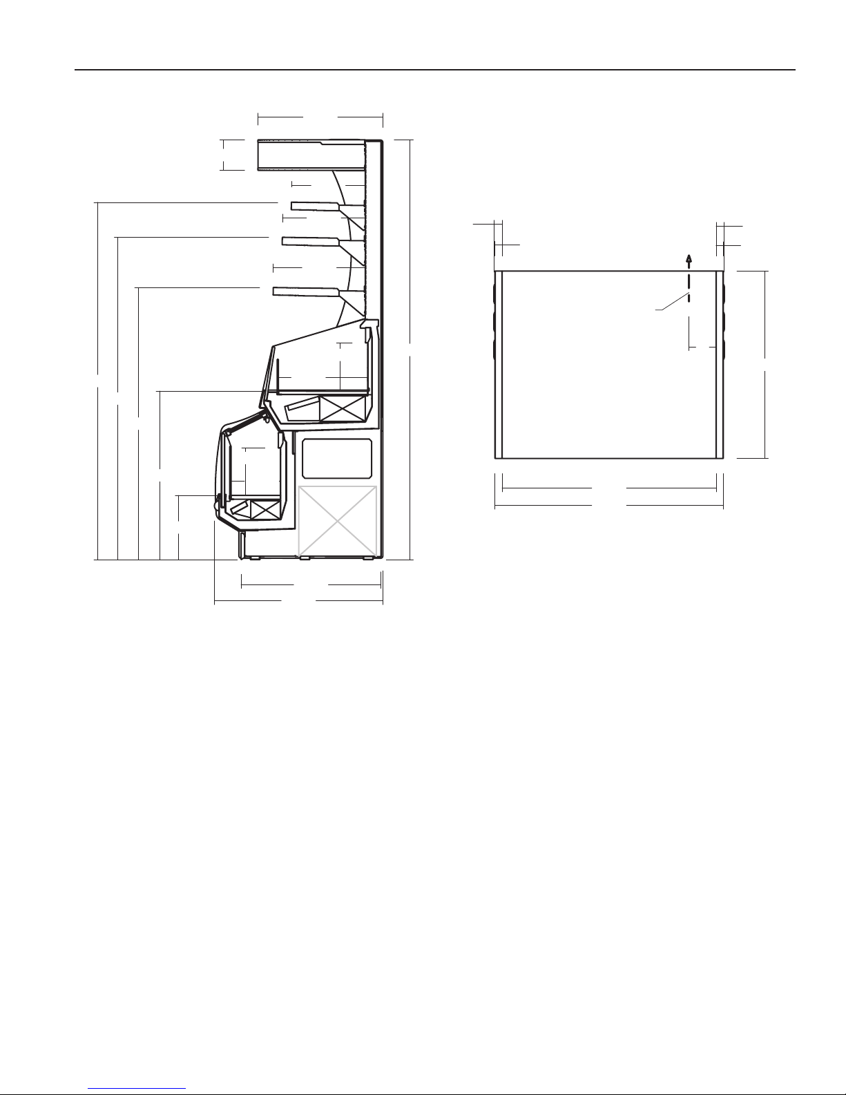
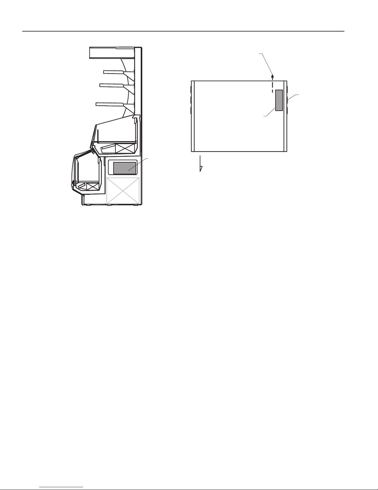
Cut and Plan Views ......................................................3
Installation.....................................................................4
Location ..................................................................................... 4
Uncrating the Stand................................................................... 4
Exterior Loading......................................................................... 4
Leveling ..................................................................................... 4
Plumbing .......................................................................4
Self Contained Cases................................................................ 4
Installing Condensate Drain (When Applicable) ........................ 4
Refrigeration .................................................................5
Refrigerant Type ........................................................................ 5
Control Settings - Remote ......................................................... 5
Access to TX Valves and Drain Lines........................................ 5
Electronic Expansion Valve (Optional)....................................... 5
Thermostatic Expansion Valve Location.................................... 5
Expansion Valve Adjustment ..................................................... 5
Measuring the Operating Superheat.......................................... 5
Omni-STAT Location.................................................................. 5
Refrigeration Data...................................................................... 6
Defrost Data............................................................................... 6
Physical Data............................................................................. 6
Glycol Requirements ................................................................. 6
Electrical........................................................................7
Wiring Color Code ..................................................................... 7
Electrical Circuit Identication.................................................... 7
Electrical Service Receptacles (When Applicable) .................... 7
Attachment Plugs....................................................................... 7
Field Wiring and Serial Plate Amperage.................................... 7
Ballast Location ......................................................................... 7
User Information...........................................................8
Stocking..................................................................................... 8
Important Steps ........................................................................ 8
Case Cleaning ........................................................................... 8
Cleaning Glass and Mirrors ....................................................... 9
Plexiglass and Acrylic Care ....................................................... 9
Cleaning..................................................................................... 9
Antistatic Coatings ..................................................................... 9
Maintenance..................................................................9
Replacing Fluorescent Lamps ................................................... 9
Evaporator Fans ........................................................................ 9
Copper Coils .............................................................................. 9
Tips and Troubleshooting .......................................................... 9
Stainless Steel Cleaning and Care.......................................... 10
Wiring Diagram ........................................................... 11
Piping Schematic........................................................13
Appendices ................................................................14
Appendix A. - Temperature Guidelines .................................... 14
Appendix B. - Application Recommendations.......................... 14
Appendix C. - Field Recommendations ................................... 14
Appendix D. - Recommendations to user................................ 15
This equipment is to be installed
to comply with the applicable
NEC, Federal, State , and Local
Plumbing and Construction
Code having jurisdiction.

Rev. 0909
3
Cut and Plan Views
83 3/8"
12 3/4"
33 1/2"
54"
64"
71"
6"
20 1/4"
18 1/4"
16 1/4"
37 1/4"
30 7/8"
27 5/8"
19 3/4"
10 7/8"
9 3/8"
9 3/8"
1 5/8"
1 7/8" 1 7/8"
1 5/8"
50 3/8"
47 1/4"
37 1/4"
6"
ELECTRICAL CONNECTION
2 POWER CORDS
1. NEMA 5-15P
2. NEMA L5-20P
MZ3-4S
PLAN VIEW
RCD
FMSS-LT
Condensing
Unit
MZ3
SELF SERVICE MERCHANDISER

IGSS-MZ3-S-0909
4
Installation
Location
The refrigerated merchandisers have been designed
for use only in air conditioned stores where temperature
and humidity are maintained at or below 75°F and 55%
relative humidity. DO NOT allow air conditioning, electric
fans, ovens, open doors or windows (etc.), to create air
currents around the merchandiser, as this will impair its
correct operation.
Product temperature should always be maintained at a
constant and proper temperature. This means that from the
time the product is received, through storage, preparation
and display, the temperature of the product must be
controlled to maximize life of the product.
Uncrating the Stand
Place the xture as close to its permanent position as
possible . Remove the top of the crate. Detach the walls
from each other and remove from the skid. Unbolt the case
from the skid. The xture can now be lifted off the crate
skid. Lift only at base of stand!
Exterior Loading
These models have not been designed to support excessive
external loading. Do not use the lower surfaces, glass,
or shelves as a stepping ladder. Do not stand in Lower
cases to gain access to the upper portion of the case.
Do not stand on any opening in the side panels. Failure
to observe these warnings could result damage to the case
and serious personal injury.
Leveling
IMPORTANT! It is imperative that cases be leveled from
front to back and side to side. A level case is necessary
to insure proper operation, water drainage, glass
alignment, and operation of the hinges supporting
the glass. Leveling the case correctly will solve most
hinge operation problems.
NOTE: A. To avoid removing concrete ooring, begin lineup
leveling from the highest point of the store oor.
B. When wedges are involved in a lineup, set them rst.
All cases were leveled and joined prior to shipment to
insure the closest possible t when cases are joined in the
eld. When joining, use a carpenters level and shim legs
accordingly. Case must be raised correctly, under legs
where support is best, to prevent damage to case.
1. Check level of oor where cases are to be set.
Determine the highest point of the oor; cases will
be set off this point.
2. Level and set the case. Case must be raised under
legs where support is best to prevent damage to
case. Internal bracing may be removed at this time.
It is the contractor's responsibility to install
case(s) according to local construction and
health codes.
Plumbing
Self Contained Cases
MZ3 self-contained cases do not require that a condensate
drain be connected because all of the condensate is
contained by the condensate pan. However it is required
that the condensate pan be cleaned on a regular basis.
Additionally, the condensing unit should be cleaned at the
same time using a light, non-abrasive brush to remove
accumulated dust. If a lter is installed, it should be cleaned
at this time as well.
Installing Condensate Drain (When Applicable)
Poorly or improperly installed condensate drains can
seriously interfere with the operation of this refrigerator, and
result in costly maintenance and product losses. Please
follow the recommendations listed below when installing
condensate drains to insure a proper installation:
1 . Never use pipe for condensate drains smaller
than the nominal diameter of the pipe or P-TRAP
supplied with the case.
2 . When connecting condensate drains, the P-TRAP
must be used as par t of the condensate drain
to prevent air leakage or insect entrance. Store
plumbing system oor drains should be at least 14"
off the center of the case to allow use of the P-TRAP
pipe section. Never use two water seals in series in
any one line . Double P-TRAPS in series will cause
a lock and prevent draining.
3 . Always provide as much down hill slope (“fall”) as
possible; 1/8" per foot is the preferred minimum.
PVC pipe, when used, must be supported to
maintain the 1/8" pitch and to prevent warping.
4 . Avoid long runs of condensate drains. Long runs
make it impossible to provide the “fall” necessary for
good drainage.
5 . Provide a suitable air break between the ood rim of
the oor drain and outlet of condensate drain. 1" is
ideal.

Rev. 0909
5
6 . Prevent condensate drains from freezing:
a. Do not install condensate drains in contact with
non-insulated suction lines. Suction lines should
be insulated with a nonabsorbent insulation
material such as Armstrong’s Armaex.
b. Where condensate drains are located in dead
air spaces (between refrigerators or between a
refrigerator and a wall), provide means to prevent
freezing. The water seal should be insulated to
prevent condensation.
Refrigeration
Refrigerant Type
The standard refrigerant will be R-404 unless otherwise
specied on the customer order. Check the serial plate on
the case for information.
Piping for more than one case on a condensing unit is run
underground with either common suction and liquid lines
from the machine room or individual suction and liquid lines
joined together in the machine room.
Refrigeration Lines
LIQUID SUCTION
3/8” O.D. 5/8” O.D.
NOTE: The standard coil is piped at 5/8” (suction); however,
the store tie-in may vary depending on the number
of coils and the draw the case has. Depending on the
case setup, the connecting point in the store may be
5/8”, 7/8”, or 1 1/8”. Refer to the particular case you are
hooking up.
Refrigerant lines should be sized as shown on the
refrigeration legend furnished by the store.
Install P-TRAPS (oil traps) at the base of all suction line
vertical risers.
Pressure drop can rob the system of capacity. To keep the
pressure drop to a minimum, keep refrigerant line run as
short as possible, using the minimum number of elbows.
Where elbows are required, use long radius elbows only.
Control Settings - Remote
See the MZ3-S Technical Data Sheet for the appropriate
settings for your merchandiser. Maintain these parameters
to achieve near constant product temperatures. Product
temperature should be measured rst thing in the morning,
after having been refrigerated overnight. Defrost times
should as directed in the MZ3-S Technical Data Sheet.
The number of defrosts per day should never change.
The duration of the defrost cycle may be adjusted to meet
conditions present at your location.
Control Settings-self Contained
All functions are controlled by Omni-Stat Controllers. See
MZ3-S Technical Data Sheet for proper temperature and
defrost settings.
Access to TX Valves and Drain Lines
MECHANICAL - Remove product from end of case.
Remove product racks. Remove refrigeration and drain
access panels (labeled). TX valve (mechanical only) and
drain are located under each access panel at end of the
case.
ELECTRONIC - The Electronic Expansion valve master
and slave cylinder(s) are located within the electrical
access panel(s).
Electronic Expansion Valve (Optional)
A wide variety of electronic expansion valves and case
controllers can be utilized. Please refer to EEV and
controller manufacturers information sheet. Sensors for
electronic expansion valves will be installed on the coil inlet,
coil outlet, and in the discharge air. (Some supermarkets
require a 4th sensor in the return air). Case controllers will
be located in the electrical raceway or under the case.
Thermostatic Expansion Valve Location
This device is located on the same side as the refrigeration
stub. An Alco balanced port expansion valve model
is furnished as standard equipment, unless otherwise
specied by customer.
Expansion Valve Adjustment
Expansion valves must be adjusted to fully feed the
evaporator. Before attempting any adjustments, make sure
the evaporator is either clear or very lightly covered with
frost, and that the xture is within 10° F of its expected
operating temperature.
Measuring the Operating Superheat
1. Determine the suction pressure with an accurate
pressure gauge at the evaporator outlet.
2. From a refrigerant pressure temperature chart,
determine the saturation temperature at the
observed suction pressure.
3. Measure the temperature of the suction gas at the
thermostatic remote bulb location.
4. Subtract the saturation temperature obtained in step
No. 2 from the temperature measured in step No. 3.
The difference is superheat.
5. Set the superheat for 5°F - 7° F
Omni-STAT Location
The Omni-Stat case controllers are located in the access
area in the right end panel. To gain access, remove the
right louvered panel. Please refer to the MZ3-S Technical
Data Sheet for the proper recommended temperature and
defrost settings.
Plumbing (Cont'd)

IGSS-MZ3-S-0909
6
ELECTRICAL CONNECTION
2 POWER CORDS
1. NEMA 5-15P
2. NEMA L5-20P
MZ3-4S
PLAN
RCD
FMSS-LT
Condensing
Unit
MZ3
SELF SERVICE MERCHANDISER
OMNI-STAT
TEMPERATURE
CONTROLLER
&
BALLASTS
OMNI-STAT
TEMPERATURE
CONTROLLER
&
BALLASTS
ACCESS
COVER
FRONT
Refrigeration (Cont'd)
Refrigeration Data
Note: This data is based on store temperature and humidity
that does not exceed 75F and 55% R.H.
Discharge Air (F) 28
Evaporator (F) 20
Note: Not recommended to control temp by regulating coil
temp allow T-STAT to cycle and control temp.
Btu/hr/ft*
Parallel 400
Conventional 460
Low Temp
Discharge Air (F) -10
Evaporator (F) -20
Note: Not recommended to control temp by regulating coil
temp allow T-STAT to cycle and control temp.
Btu/hr/ft*
Parallel 600
Conventional 690
*For all refrigeration equipment other than Hussmann, use
conventional Btu values.
Defrost Data
Frequency Hrs 8
OFFTIME
Temp Term °F 54
Failsafe Minutes 30
ELECTRIC or GAS Not Recommended
Physical Data
Merchandiser Drip Pipe (in.) 1½
Merchandiser Liquid Line (in.) 3/8
Merchandiser Suction Line (in.) 5/8
Estimated Charge (lb)***
4ft 1.2
5ft 1.5
6ft 1.8
*** This is an average for all refrigerants types. Actual
refrigerant charge may vary by approximately half a
pound.
Glycol Requirements
GPM PSI
N/A N/A

Rev. 0909
7
Wiring Color Code
Refrigerated
CASE MUST BE GROUNDED
NOTE: Refer to label afxed to case to determine the actual
conguration as checked in the “TYPE INSTALLED”
boxes.
Electrical Circuit Identication
Standard lighting for all models will be full length uorescent
lamps located on the underside of each shelf, in the freezer
section, and half-length lamps in the canopy section. The
switch controlling all lamps is located on the rear wall just
above to top of the medium temperature case (RCD) and
under the bottom shelf.
Electrical Service Receptacles (When Applicable)
The receptacles located on the exterior of the merchandiser
are intended for scales and lighted displays. They are not
intended nor suitable for large motors or other external
appliances.
Risk of Electric Shock.
This equipment has two power supply cords.
Unplug both cords before moving or servicing this equipment.
Attachment Plugs
This unit contains two power supply cords. Each cord is a
different type. Connect each plug to a single outlet circuit.
The rst attachment plug is a NEMA 5-15P type plug with
a 15 amp rating. A 15 amp line is required for the NEMA
5-15P plug. The second is a NEMA L5-20P type plug with
a 20 amp rating. A 20 amp line is require for the NEMA L5-
20P type plug. Each line must be separate with separate
circuit breakers. Do not attach both plugs to the same
electrical line!
Field Wiring and Serial Plate Amperage
Field Wiring must be sized for component amperes printed
on the serial plate. Actual ampere draw may be less than
specied. Field wiring from the refrigeration control panel to
the merchandisers is required for refrigeration thermostats.
Case amperes are listed on the wiring diagram, but always
check the serial plate.
Ballast Location
Ballasts are located within the access panel that runs the
length of the rear of the case. Refer to diagram on page 6.
Electrical

IGSS-MZ3-S-0909
8
User Information
Stocking
Improper temperature and lighting will cause serious
product loss. Discoloration, dehydration and spoilage
can be controlled with proper use of the equipment and
handling of product. Product temperature should always
be maintained at a constant and proper temperature.
This means that from the time the product is received,
through storage, preparation and display, the temperature
of the product must be controlled to maximize life of the
product.
Hussmann cases were not designed to “heat up” or “cool
down” product-but rather to maintain an item’s proper
temperature for maximum shelf life. To achieve the
protection required always:
1. Minimize processing time to avoid damaging
temperature rise to the product. Product should be
at proper temperature.
2. Keep the air in and around the case area free
of foreign gasses and fumes or food will rapidly
deteriorate.
3. Maintain the display merchandisers temperature
controls as outlined in the refrigerator section of this
manual.
4. Do not place any product into these refrigerators
until all controls have been adjusted and they
are operating at the proper temperature. Allow
merchandiser to operate a minimum of 6 hours
before stocking with any product.
5. When stocking, never allow the product to extend
beyond the recommended load limit. Air discharge
and return air ue must be unobstructed at all
times to provide proper refrigeration.
6. Keep the service doors closed (when applicable).
Refrigeration performance will be seriously affected
if left open for a prolonged period of time.
7. Avoid the use of supplemental ood or spot lighting.
Display light intensity has been designed for maximum
visibility and product life at the factory. The use of
higher output uorescent lamps (H.O. and V.H.O.), will
shorten the shelf life of the product.
Important Steps
1. Do not set temperature too cold, as this causes
product dehydration.
Recommended Omni-Stat Temperature Control
Settings:
-RCD 26°
-FMSS-LT -15°
See Case Specications for Details.
2. Temperature control is adjusted by the Omni-Stat
Temperature Controller.
Case Cleaning
Long life and satisfactory performance of any equipment
are dependent upon the care given to it. To insure long
life, proper sanitation and minimum maintenance costs,
the refrigerator should be thoroughly cleaned frequently.
SHUT OFF FAN DURING CLEANING PROCESS. It can be
unplugged within the case, or shut off case at the source.
The interior bottom may be cleaned with any domestic soap
or detergent based cleaners. Sanitizing solutions will not
harm the interior bottom, however, these solutions should
always be used according to Hussmann’s directions. It is
essential to establish and regulate cleaning procedures.
This will minimize bacteria causing discoloration which
leads to degraded product appearance and signicantly
shortening product shelf life.
CLEANING PRECAUTIONS
When cleaning:
•Do not use high pressure water hoses
•Do not introduce water faster then waste outlet can drain
•NEVER INTRODUCE WATER ON SELF CONTAINED UNIT
WITH AN EVPORATOR PAN
•NEVER USE A CLEANING OR SANITIZING SOLUTION
THAT HAS AN OIL BASE (these will dissolve the butyl
sealants) or an AMMONA BASE (this will corrode the
copper components of the case)
•TO PRESERVE THE ATTRACTIVE FINISH:
•DO USE WATER AND A MILD DETERGENT FOR THE
EXTERIOR ONLY
•DO NOT USE A CHLORANITED CLAENER ON ANY
SURFACE
•DO NOT USE ABRASIVES OR STEEL WOOL SCOURING
PADS (these will mar the finish)
C
A
U
TI
O
N
Soap and hot water are not enough to kill bacteria. A
sanitizing solution must be included with each cleaning
process to eliminate bacteria.
1. Clear debris and solid food product that may be in
areas that need cleaning.
2. Using a spray bottle, apply cleaning solution liberally
to surfaces. Thoroughly scrub all surfaces using a
non-abrasive cloth.
3. Using another spray bottle containing only water,
rinse surfaces that require rinsing. Do not use
running water to rinse. See warning above.
4. Dry completely using a clean, non-abrasive cloth.

Rev. 0909
9
Cleaning Glass and Mirrors
Only use a soft cloth and water for cleaning any glass
or mirrored components. Be sure to rinse and/or dry
completely.
Never use hot water on cold glass surfaces! It may
shatter and cause serious injury! Allow glass surfaces
to warm rst.
Plexiglass and Acrylic Care
Improper cleaning not only accelerates the cleaning cycle
but also degrades the quality of this surface. Normal daily
bufng motions can generated static cling attracting dust
to the surface. Incorrect cleaning agents or cleaning cloths
can cause micro scratching of the surface, causing the
plastic to haze over time.
Cleaning
Hussmann recommends using a clean damp chamois, or a
paper towel marketed as dust and abrasive free with 210®
Plastic Cleaner and Polish available by calling Sumner
Labs at 1-800-542-8656. Hard, rough cloths or paper towels
will scratch the acrylic and should not be used.
Antistatic Coatings
The 210®has proven to be very effective in not only
cleaning and polishing the Plexiglas surface, but also
providing anti-static and anti-fog capabilities. This product
also seals pores and provides a protective coating.
Maintenance
BEFORE SERVICING
Disconnect both Attachment Plugs to
completely De-energize unit.
Failure to disconnect both plugsmay result in
damage to equipment, serious personal injury!
This includes (but not limited to) Fans, Heaters,
Thermostats and Lights.
Replacing Fluorescent Lamps
Fluorescent lamps are furnished with moisture resistant
lamp holders, shields and end caps. Whenever a orescent
lamp is replaced, be certain to reinstall the lamp shield and
end caps over the lamp. The lamps supplied are single
slim-line or bi-pin type with or without starters.
ENCAPSULITE
SHATTERPROOF COATING - SA 10645
Complies with FDA USDA
& OSHA Regulations
for replacement call:
1-800-395-9229
Turn switch off then on after replacing bulb
NSF
U
R
R
Evaporator Fans
The evaporator fans are located at the center front of these
merchandisers directly beneath the display pans.
Copper Coils
The copper coils used in Hussmann merchandisers may
be repaired in the eld. Materials are available from local
refrigeration wholesalers.
Hussmann recommends using #15 Sil-Fos for repairs.
Tips and Troubleshooting
Before calling for service, check the following:
1. Check electrical power supply to the equipment for
connection.
2. Check xture loading. Overstocking case will affect
its proper operation.
3. If frost is collecting on xture and/or product, check
that no outside doors or windows are open- allowing
moisture to enter store.
FOR PROMPT SERVICE
When Contacting the Factory regarding problems.
Be sure to have the Case MODEL and
SERIAL NUMBER Handy. This Information
is on a plate located on the case itself.
User Information (Cont'd)

IGSS-MZ3-S-0909
10
Stainless Steel Cleaning and Care
There are three basic things, which can break down your
stainless steel’s passivity layer and allow corrosion.
1. Mechanical Abrasion
Mechanical Abrasion means those things that
will scratch the steels surface. Steel Pads, wire
Brushes, and Scrapers are prime examples.
2. Water
Water comes out of our tap in varying degrees of
hardness. Depending on what part of the country
you live in, you may have hard or soft water. Hard
water may leave spots. Also, when heated, hard
water leaves deposits behind that if left to sit, will
break down the passive layer and rust your stainless
steel. Other deposits from food preparation and
service must be properly removed.
3. Chlorides
Chlorides are found nearly everywhere. They
are in water, food and table salt. One of the worst
perpetrators of chlorides can come from household
and industrial cleaners.
Don’t Despair! Here are a few steps that can help prevent
stainless steel rust.
1. Use the Proper Tools
When cleaning your stainless steel products, take
care to use non-abrasive tools. Soft Clothes and
plastic scouring pads will NOT harm the steel’s
passive layer. Stainless steel pads can also be
used but the scrubbing motion must be in the same
direction of the manufacturer’s polishing marks.
2. Clean With the Polish Lines
Some stainless steels come with visible polishing
lines or “grain”. When visible lines are present, you
should ALWAYS scrub in a motion that is parallel to
them. When the grain cannot be seen, play it safe
and use a soft cloth or plastic scouring pad.
3. Use Alkaline, Alkaline Chlorinated or
Non-chloride Containing Cleaners
While many traditional cleaners are loaded
with chlorides, the industry is providing an ever
increasing choice of non-chloride cleaners. If you
are not sure of your cleaner’s chloride content
contact your cleaner supplier. If they tell you that
your present cleaner contains chlorides, ask for
an alternative. Also, avoid cleaners containing
quaternary salts as they also can attack stainless
steel & cause pitting and rusting.
4. Treat your Water
Though this is not always practical, softening hard
water can do much to reduce deposits. There
are certain lters that can be installed to remove
distasteful and corrosive elements. Salts in a
properly maintained water softener are your friends.
If you are not sure of the proper water treatment, call
a treatment specialist.
5. Keep your Food Equipment Clean
Use alkaline, alkaline chlorinated or non-chlorinated
cleaners at recommended strength. Clean
frequently to avoid build-up of hard, stubborn stains.
If you boil water in your stainless steel equipment,
remember the single most likely cause of damage is
chlorides in the water. Heating cleaners that contain
chlorides has a similar effect.
6. Rinse, Rinse, Rinse
If chlorinated cleaners are used you must rinse,
rinse, rinse and wipe dry immediately. The sooner
you wipe off standing water, especially when sit
contains cleaning agents, the better. After wiping the
equipment down, allow it to air dry for the oxygen
helps maintain the stainless steel’s passivity lm.
7. Never Use Hydrochloric Acid (Muriatic Acid) on
Stainless Steel
8. Regularly Restore/Passivate Stainless Steel
Maintenance (Cont'd)

Rev. 0909
11
Wiring Diagram
DATE:
PROJECT TITLE: DRAWING #:
DRAWN BY:
PRODUCTION ORDER #: DRAWING TITLE:
DATE:
Hussmann Corporation, Int'l.
13770 Ramona Avenue
Chino, CA. 91710
(909)-590-4910 Lic.#: 644406
REVISIONS:
#: DESCRIPTION: CHECKED BY:
BY:
FILE LOCATION:
JESSE RIOS
PAGE OF
ROXANNE
12
B Added defrost heater;revised load ratings 1/21/08 JR
1H07233
CIRCUIT #1
CONDENSING UNIT - COPELAND®
EJAL-A075-CAA-001
RLA= 10.9A 1112 W
MCC= 15.3A
LRA= 85.5A
225-03-0006
FANS
12W .14A @ 120VAC
(2) 00001212-A
2 FLA12 FLA
SPORLAN
OMNI STAT PLUS
952892
LEGEND
MFG WIRING
FIELD WIRING
GROUND
NEUTRAL
115V LINE
G
N
L
OMNI STAT PN952912T
-230VAC
DISPLAY UNIT
DEFROST TIMER
DISPLAY UNKIT
OMNI-STAT 115V - 60 Hz.
952892
125-01-2304
AIR TEMP DEFROST
TEMP
125-01-2301A
MAX 16 FEET
N
GROUND
FAN
COMP#1 DEFROST
SOLENOID
225-01-6004
225-01-6005
M
M
PRESSURE
SAFETY
CONDENSING UNIT
C
R
BLACK # 14
WHITE # 14
LOWER HOT GAS
DEFROST SECTION
CONDUCTIVE GLASS HEATER
10 W/FT @ 120VAC (40W .33A)
150-01-7850
WARMER (4ft) 125-01-0767
10BTV1-CR
40 WATTS
0.33AMP@120V
BLACK # 14
L1 N
***
OMNI STAT PN
952896-120VAC
POWER
SUPPLY
115Vac
PROD.
TEMP.
AIR
TEMP.
91
23
4
5
678
DEFROST TIMER
OMNI-STAT 120V - 50/60 Hz.
125-01-2303
UPPER SECTION
SOLENOID
225-01-1332
M
EVAP
FAN MOTOR
0392457
4W .29A @ 120VAC
WARMER (4ft)
125-01-0767
10BTV1-CR
40 WATTS
0.33AMP@120V
WHITE # 12
BLACK # 12
G
N
L1
POWER
CORD
20 A
NEMA
L5-20P
3 WIRES
GROUNDED
125-01-8554
SWITCH
MOTOR START
SQ "D"
125-01-0271
DEFROST HEATER
165W 1.44A @ 115VAC
00000819
MZ3-4S
CIRCUIT #1
NOTE: CASE MUST
BE GROUNDED
13.9L1
120V
LOADING
12/18/07
®

IGSS-MZ3-S-0909
12
DATE:
PROJECT TITLE: DRAWING #:
DRAWN BY:
PRODUCTION ORDER #: DRAWING TITLE:
DATE:
Hussmann Corporation, Int'l.
13770 Ramona Avenue
Chino, CA. 91710
(909)-590-4910 Lic.#: 644406
REVISIONS:
#: DESCRIPTION: CHECKED BY:
BY:
FILE LOCATION:
JESSE RIOS
PAGE OF
®ROXANNE
22
B Added defrost heater;revised load ratings 1/21/08 JR
1H07233
BUNDLE
YELLOW
DM10W-1D
1000W @ ~ 120 VAC
8.33A
125-01-0758
SAFETY
SWITCH
FLOAT SWITCH
PLUG NEMA 5-15P
G
BLACK # 14
WHITE # 14
DUPLEX
125-01-0096
CIRCUIT #2
PLUG NEMA 5-15P
125-01-0986
CIRCUIT #1
F28T5-48"
125-03-1132
BALLAST 125-01-3266
FULHAM LH3-120-L
TOGGLE SWITCH
125-01-0307
BALLAST 125-01-3266
FULHAM LH3-120-L
LIGHT CIRCUIT= 1.56A 168W
BALLAST 125-01-3266
FULHAM LH3-120-L
F28T5-48"
125-03-1132
F28T5-48"
125-03-1132
F28T5-48"
125-03-1132
SHELVES
CANOPY
F14T5-24"
(4) 125-03-1125
MZ3-4S
12/18/07
CIRCUIT #2
L1
120V
LOADING
9.6
Wiring Diagram (Cont'd)

Rev. 0909
13
Piping Schematic
20 Fv
-7 Fv
26 Fv
41 Fv
-15 Fv
27 Fv
0 Fv
-10 Fv
30 Fv
110 Fv
90F
0 Fv
106 Fv
80 Fv
80 Fv
80 Fv
2000 BTU/h
@ -15 Fv
2000 BTU/h
@ +20 Fv
ZONE 1
ZONE 2
Condenser
Heat Exchanger
Compressor
Evaporator
Evaporator
Check Valve
TXV
TXV
4-way valve
Accumulator
Receiver
EPR
Liquid
Stop Check Valve
Check Valve

IGSS-MZ3-S-0909
14
Appendices
Appendix A. - Temperature Guidelines
The refrigerators should be operated according to
Hussmann’s published engineering specifications
for entering air temperatures for specific equipment
applications. Table 1 shows the typical temperature of
the air entering the food zone one hour before the start of
defrost and one hour after defrost for various categories
of refrigerators. Refer to Appendix C for Field Evaluation
Guidelines.
TABLE 1
Type of Refrigerator Typical Entering
Air Temperature
I. OPEN DISPLAY
A. Non frozen:
1) Meat 28°F
2) Dairy/Deli 32°F
3) Produce
a. Processed 36°F
b. Unprocessed 45°F
B. Frozen 0°F
C. Ice Cream -5°F
II. CLOSED DISPLAY
A. Non frozen:
1) Meat 34°F
2) Dairy/Deli 34°F
3) Produce
a. Processed 36°F
b. Unprocessed 45°F
B. Frozen 0°F
C. Ice Cream -5°F
Single Deck Multi Deck Service Case Reach-In
I. Open Display Styles II. Closed Display Styles
Appendix B. - Application Recommendations
1.0 Temperature performance is critical for controlling
bacteria growth. Therefore, the following
recommendations are included in the standard.
They are based on conrmed eld experience
over many years.
1.1 The installer is responsible for following the
installation instructions and recommendations
provided by Hussmann for the installation of each
individual type refrigerator.
1.2 Refrigeration piping should be sized according
to Hussmann equipment recommendations and
installed in accordance with normal refrigeration
practices. Refrigeration piping should be insulated
according to Hussmann recommendations.
1.3 A clogged waste outlet blocks refrigeration. The
installer is responsible for the proper installation
of the system which dispenses condensate waste
through an air gap into the building indirect waste
system.
1.4 The installer should perform a complete start-up
evaluation prior to the loading of food into the
refrigerator, which includes such items as:
a) Initial temperature performance, Coils should
be properly fed with a refrigerant according to
Hussmann
recommendations.
b) Observation of outside inuences such
as drafts, radiant heating from the ceiling
and from lamps. Such inuence should be
properly corrected or compensated for.
c) At the same time, checks should be made of
the store dry-bulb and wet-bulb temperatures
to ascertain that they are within the limits
prescribed by the
Hussmann
.
d) Complete start-up procedures should include
checking through a defrost to make certain
of its adequate frequency and length without
substantially exceeding the actual needs.
This should include checking the electrical
or refrigerant circuits to make sure that
defrosts are correctly programmed for all the
refrigerators connected to each refrigeration
system.
e) Recording instruments should be used to
check performance.
Appendix C. - Field Recommendations
Recommendations for eld evaluating the
performance of retail food refrigerators and hot
cases.
1.0 The most consistent indicator of display
refrigerator performance is the temperature of
the air entering the product zone (Refrigerated
see Diagram 1, Appendix A). In practical use, the
precise determination of return air temperature
is extremely difcult. Readings of return air
temperatures will be variable and results will be
inconsistent. The product temperature alone is
not an indicator of refrigerator performance.
NOTE: Public Health will use the temperature of the product in
determining if the refrigerator will be allowed to display
potentially hazardous food. For the purpose of this
evaluation, product temperature above the FDA Food
Code 1993 temperature for potentially hazardous food
will be the rst indication that an evaluation should
be performed. It is expected that all refrigerators will
keep food at the FDA Food Code 1993 temperature for
potentially hazardous food.

Rev. 0909
15
Appendices (Cont'd)
1.1 The following recommendations are made for the
purpose of arriving at easily taken and understood
data which, coupled with other observations,
may be used to determined whether a display
refrigerator is working as intended:
a) INSTRUMENT - A stainless steel stem-type
thermometer is recommended and it should
have a dial a minimum of 1 inch internal
diameter. A test thermometer scaled only
in Celsius or dually scaled in Celsius and
Fahrenheit shall be accurate to 1°C (1.8°F).
Temperature measuring devices that are
scaled only in Fahrenheit shall be accurate to
2°F. The thermometer should be checked for
proper calibration. (It should read 32°F when
the stem is immersed in an ice water bath).
b) LOCATION - The probe or sensing element
of the thermometer should be located in
the airstream where the air rst enters the
display or storage area, and not more than 1
inch away from the surface and in the center
of the discharge opening.
c) READING - It should rst be determined
that the refrigerator is refrigerating and has
operated at least one hour since the end
of the last defrost period. The thermometer
reading should be made only after it has
been allowed to stabilize, i.e., maintain a
constant reading.
d) OTHER OBSERVATIONS - Other
observations should be made which may
indicate operating problems, such as
unsatisfactory product, feel/appearance.
e) CONCLUSIONS - In the absence of any
apparent undesirable conditions, the refrigerator
should be judged to be operating properly. If it is
determined that such condition is undesirable,
i.e., the product is above proper temperature,
checks should be made for the following:
1. Has the refrigerator been loaded with
warm product?
2. Is the product loaded beyond the “Safe
Load Line” markers?
3. Are the return air ducts blocked?
4. Are the entering air ducts blocked?
5. Is a dumped display causing turbulent air
ow and mixing with room air?
6. Are spotlights or other high intensity
lighting directed onto the product?
7. Are there unusual draft conditions (from
heating /air-conditioning ducts, open
doors, etc.)?
8. Is there exposure to direct sunlight?
9. Are display signs blocking or diverting
airow?
10.Are the coils of the refrigerator iced up?
11. Is the store ambient over 75°F, 55% RH
as set forth in ASHRAE Standard 72 and
ASHRAE Standard 117?
12.Are the shelf positions, number, and size
other than recommended by Hussmann?
13.Is there an improper application or control
system?
14.Is the evaporator fan motor/blade
inoperative?
15.Is the defrost time excessive?
16.Is the defrost termination, thermostat
(if used) set too high?
17.Are the refrigerant controls incorrectly
adjusted?
18.Is the air entering the condenser above
design conditions? Are the condenser ns
clear of dirt, dust, etc.?
19.Is there a shortage of refrigerant?
20. Has the equipment been modied to use
replacements for CFC-12,
CFC-502 or other refrigerant? If so,
have the modications been made in
accordance with the recommendations
of Hussmann’s equipment? Is the
refrigerator charged with the proper
refrigerant and lubricant? Does the system
use the recommended compressor?
Appendix D. - Recommendations to user
1.0 Hussmann should provide instructions and
recommendations for proper periodic cleaning.
The user will be responsible for such cleaning,
including the cleaning of low temperature
equipment within the compartment and the
cooling coil area(s). Cleaning practices,
particularly with respect to proper refrigerator
unloading and warm-up, must be in accordance
with applicable recommendations.es Continued
1.1 Cleaning of non frozen food equipment
should include a weekly cleaning of the food
compartment as a minimum to prevent bacteria
growth from accumulating. Actual use and
products may dictate more frequent cleaning.
Circumstances of use and equipment design
must also dictate the frequency of cleaning the
display areas. Weekly washing down of the
storage compartment is also recommended,
especially for equipment subject to drippage
of milk or other liquids, or the collection of

IGSS-MZ3-S-0909
16
Appendices (Cont'd)
For further technical information, please log on to http://www.hussmann.com/products/MZ3.htm
vegetable, meat, crumbs, etc., or other debris
or litter. Daily cleaning of the external areas
surrounding the storage or display compartments
with detergent and water will keep the equipment
presentable and prevent grime buildup.
1.2 Load levels as dened by Hussmann must be
observed.
1.3 The best preservation is achieved by following
these rules:
a) Buy quality products.
b) Receive perishables from transit equipment
at the ideal temperature for the particular
product.
c) Expedite perishables to the store’s storage
equipment to avoid unnecessary warm-up
and prolonged temperature recovery. Food
store refrigerators are not food chillers nor
can they reclaim quality lost through previous
mishandling.
d) Care must be taken when cross
merchandising products to ensure that
potentially hazardous vegetable products are
not placed in non refrigerated areas.
e) Display and storage equipment doors should
be kept closed during periods of inactivity.
f) Minimize the transfer time of perishables
from storage to display.
g) Keep meat under refrigeration in meat cutting
and processing area except for the few
moments it is being handled in processing.
When a cut or tray of meat is not to be
worked on immediately, the procedure should
call for returning it to refrigeration.
h) Keep tools clean and sanitized. Since
mechanical equipment is used for fresh
meat processing, all such equipment should
be cleaned at least daily and each time
a different kind of meat product comes in
contact with the tool or equipment.
i) Make sure that all refrigeration equipment is
installed and adjusted in strict accordance
with Hussmann’s recommendations.
j) See that all storage and refrigeration
equipment is kept in proper working order by
routine maintenance.

The MODEL NAME and SERIAL NUMBER is required in order to provide
you with the correct parts and information for your particular unit.
They can be found on a small metal plate on the unit.
Please note them below for future reference.
MODEL:
SERIAL NUMBER:
/Chino
Additional copies of this publication may be obtained by contacting:
Hussmann® Chino
13770 Ramona Avenue • Chino, California 91710
(909) 628-8942 FAX
(909) 590-4910
(800) 395-9229
Service Record
Last service date: By:
_______________ __________________________________________________________________________________________________
_______________ __________________________________________________________________________________________________
_______________ __________________________________________________________________________________________________
_______________ __________________________________________________________________________________________________
_______________ __________________________________________________________________________________________________
_______________ __________________________________________________________________________________________________
_______________ __________________________________________________________________________________________________
IGSS-MZ3-S-0909
Table of contents
Other Hussmann Refrigerator manuals

Hussmann
Hussmann Innovator Manual

Hussmann
Hussmann CR3-HV-SWD User manual

Hussmann
Hussmann Chino RDI-27 Original operating instructions

Hussmann
Hussmann VRM1B User manual

Hussmann
Hussmann DD5X5FRW User manual

Hussmann
Hussmann DDSS-4MC User manual

Hussmann
Hussmann DBP-01 Operating instructions

Hussmann
Hussmann Proto-Aire User manual

Hussmann
Hussmann GIM Quick guide

Hussmann
Hussmann Super Plus User manual