Huvema BL 50 AIR User manual

BL 50 AIR
AIRCOMPRESSOR

2CHANGES AND TYPING ERRORS RESERVED CHANGES AND TYPING ERRORS RESERVED
Table of conTenTs
1. General safety rules for all machines 3
2. Additional safety rules 4
3. Specification 4
4. Machine parts 4
5. Getting started 4
6. Assembly 5
6.1 Installing the wheels 5
6.2 Installing the Oil and Oil Breather 5
6.3 Installing the Air Filter 5
7. Operation 6
7.1 Before operating your new air compressor 6
7.2 Initial Start-Up Procedure 6
7.3 General Overview 6
7.4 Installation and Location 6
7.5 Connecting to Power Source 6
7.6 Extension Cords 6
7.7 Attaching an Air Hose 6
7.8 Adjusting the Air Pressure 7
8. Maintenance 7
8.1 Weekly 7
8.2 Monthly 7
8.3 Checking the Air Compressor Oil 7
8.4 Changing the Air Compressor Oil 7
9. Troubleshooting 8
10. Explosion Drawing and Parts List 8
10.1 Explosion drawing A 8
10.2 Parts list A 9
10.3 Explosion drawing B 10
10.4 Parts list B 11

3
CHANGES AND TYPING ERRORS RESERVED CHANGES AND TYPING ERRORS RESERVED
bl50 air
1. General safeTy rules for all machines
N.B.: Read the instructions carefully in order to avoid any problems.
As with all machinery there are certain hazards involved with operation and use of this machine. Using the
machine with respect and caution will considerably lessen the possibility op personal injury. However, if normal
safety precautions are overlooked or ignored, personal injury to the operator may occur. Observe these rules
insofar as they are applicable to this particular machine.
This machine was designed for certain applications only. We strongly recommend that this machine NOT be
modified in any way and/or used for any application other than for which it was designed.
If you have any questions relative to its application DO NOT use the machine until you have contacted your
dealer.
1. For your own safety read the instruction manual before operating the tool.
2. Keep all guards in place and in working order.
3. Ground all tools.
4. Remove adjusting keys and wrenches. Make a habit of checking the machine before turning it on.
5. Keep the work area clean. Cluttered areas and benches invite accidents.
6. Do not use in a dangerous environment, such as damp or wet locations or expose to rain. Always keep the
work area well-lit.
7. Keep children and visitors away. They must be kept at a safe distance from the machine at all times.
8. Make sure that the work area is not accessible to unauthorised persons. Use padlocks, master switches,
remove starter keys etc.
9. Never overload the machine. The capacity of the machine is at its largest when properly loaded.
10. Do not force the machine or attachment to do a job for which it was not designed.
11. Wear proper apparel. No loose clothing, gloves, neckties, rings, necklaces, bracelets or jewellery: they may
get caught in moving parts. No slip footwear is recommended. Wear a hairnet to contain long hair.
12. Always wear safety glasses and work according to safety regulations. Use a face or dust mask if operation is
dusty.
13. Always secure workpiece tightly using a vise or clamping device. This will keep both hands free to operate
the machine.
14. Do not overreach. Keep your proper footing and balance at all times.
15. Maintain tools in top condition. Keep them sharp and clean. Read the instructions carefully and follow the
instructions for cleaning, lubrication and tool replacement.
16. Lubricate the machine and fill all oil reservoirs before operation.
17. Disconnect tools before servicing and when changing accessories such as blades, bits, cutters etc.
18. Use only recommended accessories. Consult the owner’s manual for recommended accessories. The use of
improper accessories may cause hazards.
19. Avoid accidental starting. Make sure the on/off switch is in the “OFF”position before plugging in the power
cord.
20. Never stand on the machine or tools. Serious injury could occur if the machine is tipped or if the cutting tool
is accidentally touched.
21. Check damaged parts. Replace or repair damaged parts immediately. Check machine for alignment of
moving parts, binding of moving parts, breakage of parts, mounting and any other conditions that may
affect its operation.
22. Direction of feed. Feed work into a blade or cutter against the direction of rotation of the blade or cutter
only.
23. Never leave tool running unattended. Do not turn power off until it has come to a complete stop.
24. Alcohol, medication, drugs. Never us the machine while under the influence of alcohol, medication or drugs.
25. Make sure the tool is disconnected from the power supply, before servicing, repairing etc.
26. Keep the original packing for future transport or relocation of the machine.

4CHANGES AND TYPING ERRORS RESERVED CHANGES AND TYPING ERRORS RESERVED
2. addiTional safeTy rules
Always keep in mind that:
• the machine must be switched off and disconnected from the power supply during maintenance and repairs,
• clamped workpieces may only be measured when the machine is switched off.
Never lean over the machine, mind loose clothing, ties, jewellery etc. and wear a cap.
Do not remove safety devices or guards. Never use the machine while a guard is open.
Always use safety glasses for machining rough materials.
Burrs and chips should only be removed using a sweeper or other aid, never with your bare hands!
Never leave the machine running unattended.
Always wear safety glasses!
3. specificaTion
Tank capacity 50 l Speed 2850 min-1
Motor power 1.5 kW Voltage 230 V
Max. consumption 198 ltr/min Weight 35 kg
Max. pressure 8 bar Dimensions (w x h) 785 x 325 x 665 mm
4. machine parTs
Air Regulator: The Air Regulator controls the air flow pressure. Tum regulator clockwise to increase air pressure,
counter-clockwise to decrease.
Handle: Convenient, rubber gripped handle allows for easy transport of your Air compressor.
Air Outlet: Using Air Quick Coupler allows for fast easy connection to an air hose. Otherwise Air Cock turn
clockwise to stop air, turn counter-clockwise to release air.
Tank Drain Valve: The Tank Drain Valve can be opened to allow moisture and compressed air to be released from
the air Tank.
Warning: Tank Drain Valve should always be opened slowly to avoid damage to equipment and possible
injury.
Air Filter: This Air filter keeps your compressor running cleanly, by filtering out impurities.
Oil Breather: As the compressor motor operates pressurized air must be released from the crank case. The Oil
Breather allows built up air to escape, while shielding you Air Compressor from airborne impurities.
Pressure Switch: The red knob Pressure Switch turns the Air Compressor on and off. When Switch -is pulled-up
position, compressor is turned ON. When switch is in pushed - down position, compressor is turned OFF.
Note: Always make sure that compressor Pressure Switch is in the OFF position before performing and
maintenance or plugging the compressor into a power supply.
Safety Valve: The Safety Valve device relieves pressure from the Air Tank in the event of excessive pressure build
up. The Safety Valve is preset at factory. Do not attempt to make any adjustments to the Safety Valve. Periodically
pull ring on the Safety Valve end to check that it is working properly.
Air Tank: Powder coated steel tank, stores the compressed air until it is needed.
1.ing it clockwise.
2. The spindle return spring adjustment is complete.
5. GeTTinG sTarTed
Before operating your tool, check the contents of the box to make sure you have everything you need.
Items included in the box:
• Air Compreessor
• Air Filter
• Oil Breather
• Wheels(2)
• Mounting Hardware for Wheels
• Owner’s Manual

5
CHANGES AND TYPING ERRORS RESERVED CHANGES AND TYPING ERRORS RESERVED
6. assembly
Note: Before performing any assembly or maintenance make
compressor be turned off and unplugged from the power supply.
6.1 insTallinG The wheels
1. Locate the wheels, hex bolts, washers, and wheel nuts.
2. Insert hex bolt through wheel rim and wheel bracket in place located on the bottom rear of the air
compressor.
3. Slide washer on the end of bolt.Securely tighten bolts and wheel nuts in place with a wrench.
4. Repeat step 2 to 3 for remaining wheel. (fig 1)
Fig 1
6.2 insTallinG The oil and oil breaTher
Before you starting the air compressor please remove the white oil stopper and add oil into crankcase.
Before starting the air compressor you must verify oil the crankcase and install the oil breather as described
below:
1. Place compressor on level ground.
2. Remove the Plastic Oil Stopper the Oil Fill Hole.
3. Verify oil in the Crankcase.lf the oil level down to the center of the red dot on the oil Sight Glass, slowly pour
the oil into the Oil Fill Hole until the oil level rises to the red dot.
4. Insert the Oil Breather into the Oil Fill Hole. Firmly hand tighten the Oil Breather by turning clockwise.
Note: This compressor uses only SAE20 or SAE30 non-detergent motor oil. (See Figure2.1-2.2)
Figure 2.1 Figure 2.2
6.3 insTallinG The air filTer
The Air Filter is installed into the threaded port of the Cylinder Head.
1. Thread the Air Filter into the Cylinder Head by turning the Air Filter clockwise.
2. Securely tighten the Air Filter in place with a wrench.
Note: DO NOT over tighten Air Filter.

6CHANGES AND TYPING ERRORS RESERVED CHANGES AND TYPING ERRORS RESERVED
7. operaTion
7.1 before operaTinG your new air compressor
Please check the following points carefully:
1. Check that all nuts and bolts are secure.
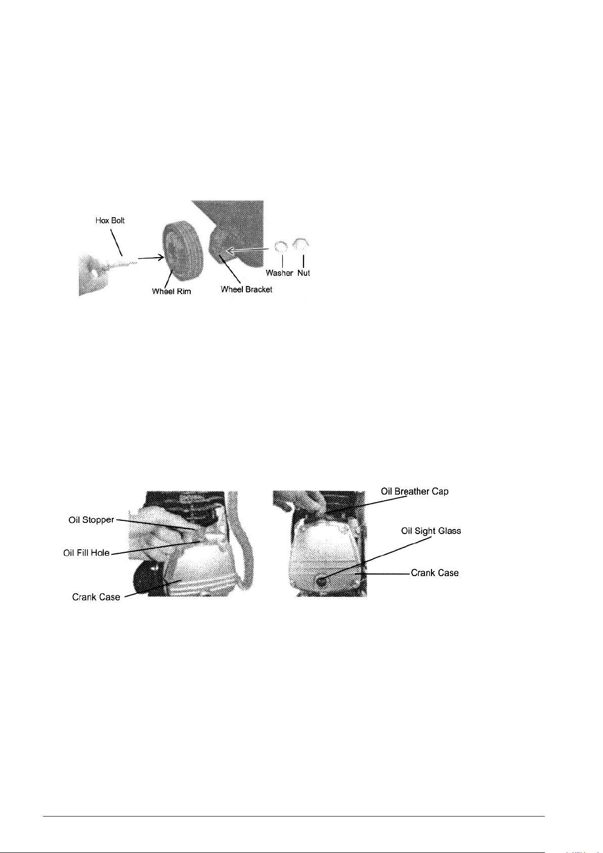
2. Make sure oil has been properly added to compressor.
(See installing the Oil and Oil Breather section)
7.2 iniTial sTarT-upprocedure
1. Open the Air Tank Drain Valve to permit air to escape preventing air from pressure buildup in Air Tank.
2. Run the air compressor for a minimum of 20minutes in this “up-load”position to libricate the piston and
bearing.
3. Close Air Tank Drain Valve . Your compressor is ready for use.
Depending on the CFM draw of the tools being operated, your new Air C ompressor can be used for operating
paint sprayers, air tools, grease guns, air brushed, caulking guns, abrasive blasters, tire & plastic toy inflation,
spraying weed killer and insecticides, etc. Proper adjusting the Air Pressure Regulator is necessary for all of these
operations. Refer to the air pressure specifications provided with the tool you are using.
7.3 General overview
To compress air, the piston moves up and down in the cylinder. On the down stroke air is drawn in through the
valve inlet. The discharge valve remains closed. On the upstroke of the piston air is compressed; the inlet valve
closes and air is forced out through the discharge valve ,through the check valve, and into the air tank. Working
air is not available untill the compressor has raised; the tank pressure above that required in the air service
connection. The air inlet filter openings must be kept clear off obstructions, which could reduce air delivery of the
compressor.
7.4 insTallaTion and locaTion
Locate the compressor in a clean, dry and well ventilate area. The compressor should be located 12 to 18 inches
against walls or any other obstruction which would interfere with airflow. Place the compressor on a firm, level
surface. Keep all of spare parts which collect dust or dirt clean. A clean compressor runs cooler and provides
longer servisce. Do not place rag, containers or other materials on top of the compressor.
7.5 connecTinG To power source
This Air Compressor is designed to operate on a properly grounded 220 (110) V, 50(60)HZ, single phase,
alternating current (AC) power source. It is recommended that a qualified electrician verify the ACTUAL VPLTAGE
at the receptacle into which unit will be plugged and confirm that the receptacle is properly fused and grounded.
The use of the proper circuit size can eliminate nuisance circuit breaker tripped whie operating your air
compressor.
7.6 exTension cords
For optimum Air Compressor performance an extension cord should not be used unless absolutely necessary. If
necessary, care must be taken to select an extension cord appropriate for use with your specific Air Compressor.
Select a properly grounded extension cord which will mate directly with the power source receptacle and the Air
Conpressor power cord without the use of adapters. Make certain the extnsion cord is properly wired and in good
electrical condition. Extension cords must be #14 gauge or I mm2 at the smallest. Do not
use an extension cord over 25ft. in length.
7.7 aTTachinG an air hose
Your Air Compressor is ready to accept air hoses with (1/4”)Male Plug or (1/4”)Female Hose End. To install an air
hose into Air Cock or Air Quick Coupler, equipped with proper conneeter. Verify that air hose is
securely connected to Air Outlet by pulling lightly on air hose.
Note: Use only Air Hoses rated for use with 115PSI air pressure or higher.
7.8 adjusTinG The air pressure

7
CHANGES AND TYPING ERRORS RESERVED CHANGES AND TYPING ERRORS RESERVED
Your Air Compressor is equipped with an air pressure requlator. This regulator adjust the air pressure.
To increase Air Pressure, turn Air Regulator clockwise.
To decrease air pressure, turn Air Regulator counterclockwise.
8. mainTenance
DAILY (or before each use)
l. Check oil level
2. Drain condensation from the Air Tank.
3. Check for any unusual noise or vibration.
4. Be sure all nuts and bolts are tight.
8.1 weekly
Clean breather hole on oil breather.
8.2 monThly
Inspect air system for leaks by applying
Tighten these joints if leaks are discovered.
or after 250hourse of operation-whichever comes first)
Change air compressor oil.
Note: Change oil more often if air compressor is used near paint
spraying operations or in dusty environments.
8.3 checkinG The air compressor oil
1. Place Air Compressor on level surface. The oil level should be at
the red dot on the Oil Sight Glass.
2. If oil level is low, remove Oil Breather and add enough oil to
bring the oil level to the red dot on the Oil Sight Glass.
3. Replace Oil Breather before starting compressor.
8.4 chanGinG The air compressor oil
1. Remove the Oil Sight Glass by tuming counter clockwise with wrench.
Note: Oil will begin to drain as Oil Sight Glass is loosened.Place a funnel and oil pan in place before
loosening Oil Sight Glass.
2. Once Oil Sight Glass is removed, tilt Air Compressor backwards to allow all of the oil to drain out of the
crankcase.
3. Once oil is drained, replace Oil Sight Glass and securely tighten in place with a wrench. Be careful not to over
tighten the Oil Sight Glass, this will damage the rubber seal.
4. Place Air Compressor on level surface.
5. Remove the Oil Breather.
6. Slowly pour the oil into Oil Fill Hole, untill the oil level rises to the center of the red dot on the Oil Sight Glass.
7. Install the Oil Breather into the Oil Fill Hole. Firmly hand tight the Oil Breather by turning clockwise.
Always inspect the tool before use, and make sure it is in good working condition. Make sure all air vents are clear,
(use compressed air to clean the machine if possible). Check the power cable to make sure it is intact and free
from cracks, bare wires etc. To avoid using solvents when cleaning plastic parts, most plastic are susceptible to
damage from the various types of commercial solvents.

8CHANGES AND TYPING ERRORS RESERVED CHANGES AND TYPING ERRORS RESERVED
9. TroubleshooTinG
Trouble Possible cause Corrective action
Compressor won’t start 1 Blowen fuse or Circuit breaker
tripped.
2. Loose electrical connections
1. Replace or Reset Fuse/ Circuit
Breaker
2. Check Wiring connections
Low Pressure 1. Restricted Air Filter
2. Defective Check Valve
3. Air Leak in Safety Valve
1. Replace Air filter
2. Replace Air Valve
3. Check Valve by pulling upwards
on ring. If condition persists,
replace valve.
Safety Valve Releasing 1. Defective Pressure Switch 1. Replace Pressure Switch
Oil Discharge in Air 1. Improper Oil Viscosity
2. Too much oil in Crankcase
3. Compressor over heated
4. Restricted oil Breather
1. Replace oil with SAE20 or SAE30
no-detergent oil.
2. Drain Crankcase and refill to
proper level on Oil Sight Glass
3. Reduce air pressure regulation
4. Clean or Replace Oil Breather.
10. explosion drawinG and parTs lisT
10.1explosion drawinG a

9
CHANGES AND TYPING ERRORS RESERVED CHANGES AND TYPING ERRORS RESERVED
10.2parTs lisT a
NO. Description Q'TY NO. Description Q'TY
1Bolt 239 Spring Washer 2
2Wheel 240 Plain Washer 2
3Spring Washer 241 Capacitor 1
4Nut 242 Bearing 1
5Drain Valve 143 Oil Seal 1
6Tank 144 Stator 1
7Stopper 245 Bolt 4
8Bolt 146 Spring Washer 4
9Plain Washer 147 Cylinder Head 1
10 Foot Support 148 Elbow 1
11 Plain Washer 149 Pipe 1
12 Spring Washer 150 Cylinder Gasket 1
13 Nut 151 Bolt 2
14 Plug 152 Spring Washer 2
15 Check Valve 153 Crank case 1
16 Pipe 154 Air Filter 1
17 Handle Cover 155 Cylinder Head Gasket 1
18 Saferty Valve 156 Valve Plate 2
19 Pressure Switch 157 Valve 2
20 Pressure Gauge 158 Aluminium Gasket 1
21 Connector 159 Valve Plat Gasket 1
22 Pressure Gauge 160 Cylinder 1
23 Water Filter 161 Piston Ring 1
24 Air Cock 162 Piston 1
25 Cover 163 Piston Pin 1
26 Bolt 664 Circlip 2
27 Bolt 465 Connecting Rod 1
28 Spring Washer 466 Crankshaft 1
29 Circlip 167 Bolt 1
30 Fan 168 Gasket 1
31 Rear Support 169 Oil Breath 1
32 Bolt 170 Front Cover 1
33 Gasket 171 Bolt 4
34 Ground Connection 172 Oil Pointer 1
35 Gasket 173 Gasket 1
36 Bearing 174 Bolt 1
37 Rotor 175 O Ring 1
38 Bolt 276 Quick Coupler 1

10 CHANGES AND TYPING ERRORS RESERVED CHANGES AND TYPING ERRORS RESERVED
10.3explosion drawinG b

11
CHANGES AND TYPING ERRORS RESERVED CHANGES AND TYPING ERRORS RESERVED
NO. Description Q’TY NO. Description Q’TY
1Cover 138 Capacitor 1
2Bolt 639 Stator 1
3Elbow 140 Gasket 1
4Bolt 441 Screw 1
5Spring Washer 442 Gasket 1
6Plain Washer 443 Ground Connection 1
7Cylinder Head 144 Rear Support 1
8Air Filter 145 Fan 1
9Cylinder Head Gasket 146 Circlip 1
10 Valve Plate 247 Spring Washer 4
11 Valve 248 Bolt 4
12 Aluminum 149 Quick Coupler 1
13 Valve Plat Gasket 150 Water Filter 1
14 Cylinder 151 Connector 1
15 Cylinder Gasket 152 Pressure Switch 1
16 Bolt 253 Safety Valve 1
17 Spring Washer 254 Pipe 1
18 Piston Ring 155 Pressure Gauge 1
19 Piston 156 Pressure Gauge 1
20 Piston Pin 157 Connector 1
21 Circlip 258 Plug 1
22 Connecting Rod 159 Screw 4
23 Crankshaft 160 Handle 1
24 Bolt 161 Tank 1
25 Gasket 162 Bolt 2
26 Oil Breath 163 Wheel 2
27 Front Cover 164 Spring Washer 2
28 Bolt 465 Nut 2
29 Oil Pointer 166 Drain Valve 1
30 Gasket 167 Bolt 1
31 Screw 168 Plain Washer 2
32 O Ring 169 Foot Support 2
33 Crank Case 170 Plain Washer 2
34 Oil Seal 171 Spring Washer 2
35 Bearing 172 Nut 2
36 Rotor 173 Checl Valve 1
37 Bearing 174 Pipe 1
10.4 parTs lisT b

12 CHANGES AND TYPING ERRORS RESERVED CHANGES AND TYPING ERRORS RESERVED
Our products are frequently updated and improved. Minor changes may not yet be incorporated in this manual.
Always state the year of build, type and serial number of the machine in correspondence.
Manufacturer and importer assume no responsibility for defects which result from not reading the manual
carefully or wrong use of the machine. No rights can be derived from this manual.
All rights reserved. No part of this booklet may be reproduced in any form, by print, photoprint, microfilm or any
other means without written permission from the publisher.
© Huberts bv, Kennedylaan 14, Veghel, the Netherlands. Internet: www.huvema.nl

13
CHANGES AND TYPING ERRORS RESERVED CHANGES AND TYPING ERRORS RESERVED
CE DECLARATION OF CONFORMITY
(in accordance with supplement II A of the Machinery Directive)
Industrie & Handelsonderneming Huberts bv, Kennedylaan 14, 5466 AA Veghel, the Netherlands,
in the capacity of importer, is to be held responsible for declaring that the Huvema machine:
Aircompressor BL 50 air which this declaration relates to, is conform the following norms:
NEN-EN-ISO 12100:2010, NEN-EN-IEC 60204-1:2006/C11:2010, NEN-EN-IEC 61000-6-4:2007,
NEN-EN-IEC 61000-6-2:2007
As described in the:
• Machinery Directive: 2006/42/EC
• Low Voltage Directive: 2006/95/EC
• EMC Directive: 2004/108/EC
Veghel, the Netherlands, January 2017
L. Verberkt
Managing Director

2017 V1
Table of contents
Other Huvema Air Compressor manuals
Popular Air Compressor manuals by other brands

Draper
Draper Da160 instructions

Sullair
Sullair ES-6 series Operator's manual and parts list

Sullair
Sullair LS-25 Operator's manual and parts list

Campbell Hausfeld
Campbell Hausfeld FP204020 Operating instructions and parts manual

Truper
Truper COMP-30S manual

CompAir
CompAir 5280D.1.IAC Operator's handbook