HW group
www.HW-group.com 3
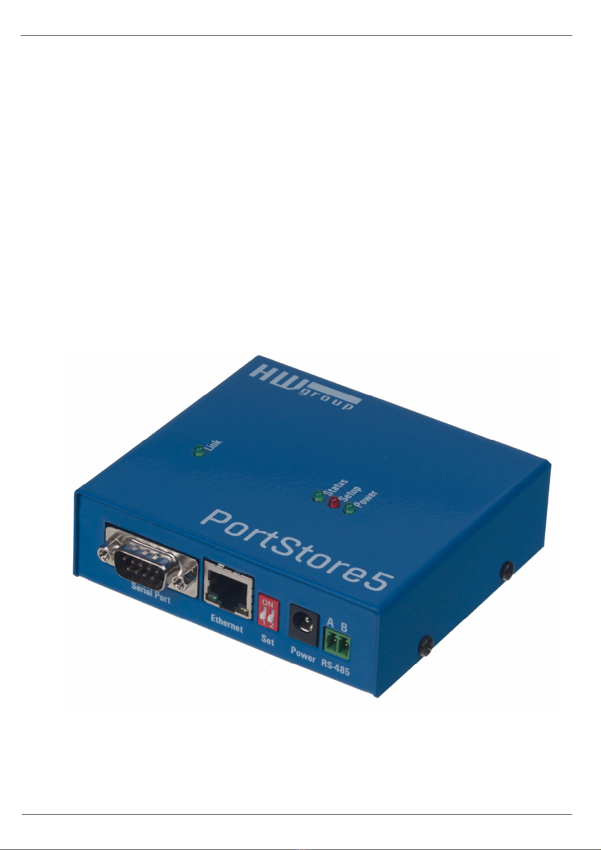
PortStore5
RS-232 or RS-485 to Ethernet converter + 4 MB serial buffer + system messages by e-mail
PortStore5 is an Ethernet to serial
converter (“terminal server”), featuring
support for full 9-bit RS-232 and RS-485
serial ports and 4096 kB Flash buffer for
storing data whenever the TCP
connection is unavailable.
In the TCP Client/Server mode,
PortStore5 automatically establishes a
TCP connection and attempts to upload
data to the server.
If the internal buffer is full, an e-mail
alert is sent.
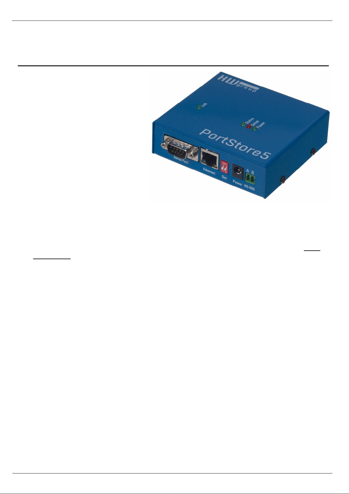
Basic features
ƒ1x full RS-232 (9-pin) or RS-485 serial port accessible over the Ethernet.
ƒSerial port data are stored in a 4096 kB Flash buffer and uploaded after establishing a TCP
connection. When the connection is established, stored data are sent as a continuous “RAW
TCP stream”.
ƒThe remote port can be controlled with a virtual driver for Windows just like, for example,
COM 5 (a Windows XP / Vista / Windows 7 / Windows 8 / Server 2003 / Server 2008 / x64
driver is available free of charge). Compatible with RFC2217.
ƒ100 Mbps Ethernet interface – 100BASE-Tx, RJ45.
ƒSupport for TCP/IP terminal, TELNET – NVT type (Network Virtual Terminal).
ƒTwo devices can „tunnel“ the serial port over the Ethernet.
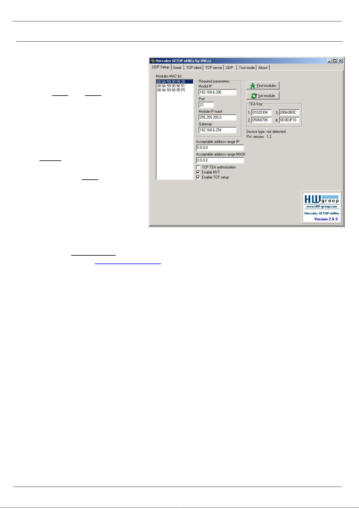
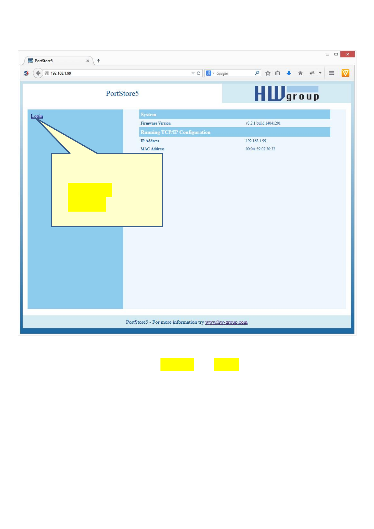
ƒWeb-based configuration interface.
ƒWide range of supported serial interface parameters:
oCommunication speed configurable from 300...115200 Bd
oHandshake (CTS/RTS, Xon/Xoff, none)
oFull serial port (Cannon DB9M - RxD, TxD, CTS, RTS, DSR, DTR, RI, CD, GND)
oSupport for 7th to 9th parity bit (9th parity bit transferred over the Ethernet)
ƒSDK (Software Development Kit) is available for the device with examples for MS Visual Basic,
Delphi, Borland C++, JAVA, PHP and more.