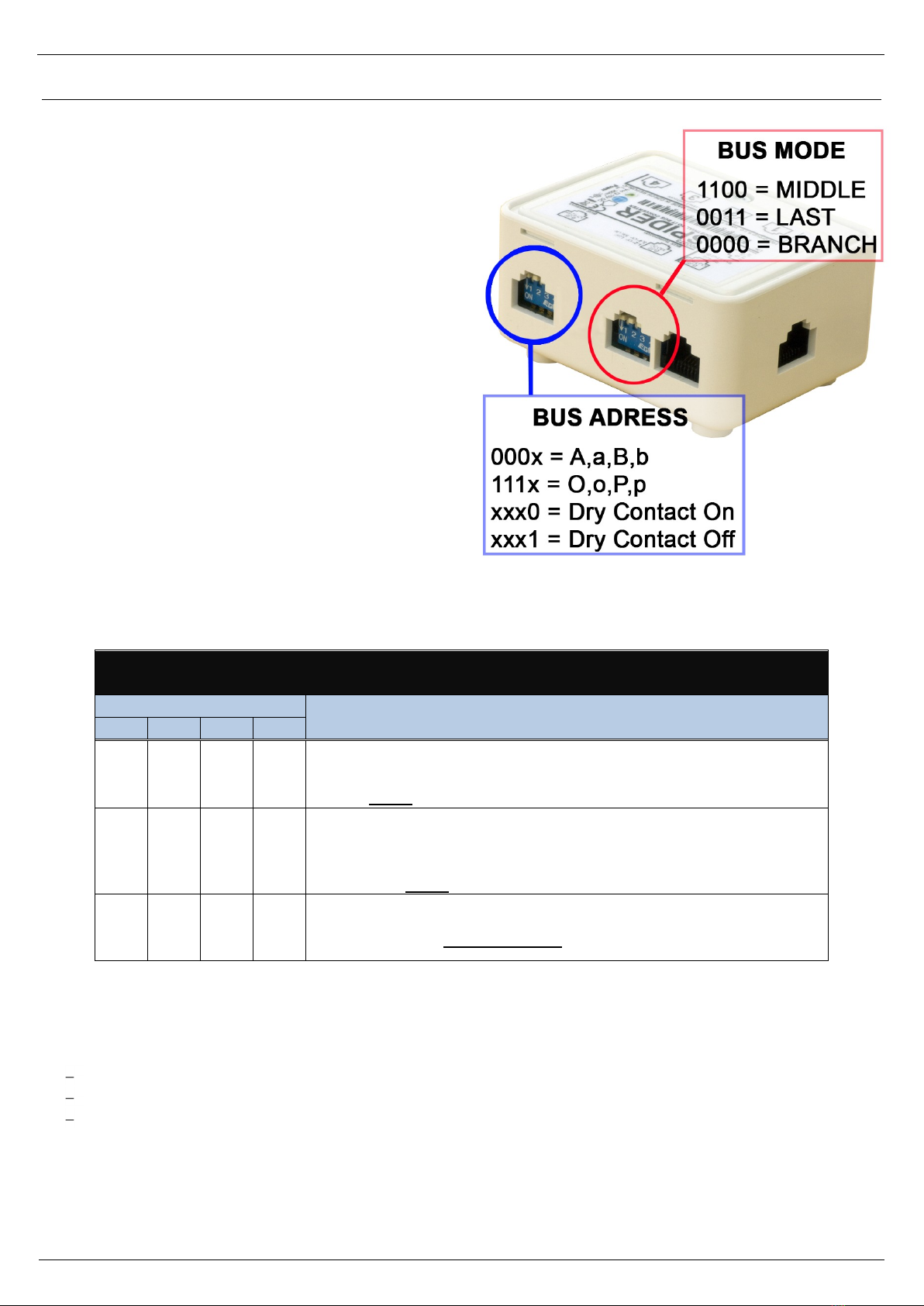
HW Group Spider User manual

Spider
Six 1-Wire probes on the RS-485 bus
EN 600 273

Spider
HW group
www.HW-group.com
2
Spider is a converter for connecting up to 4 1-Wire probes (max 6 values) or 4 dry contacts to the
RS-485 bus. Spider is designed to work with Poseidon 2250.
Input
4x 1-Wire probe (temperature or humidity)
6 values (at most 2 combined temp/humidity probes can be connected)
4x dry contact
Output
RS-485 bus –RJ45 (includes power)
Poseidon 2250 supports up to 26 probes or 4 Spider units in total
An extra power supply adapter is required to connect two or more Spiders
The RS-485 communication bus can be up to 1200m (4000ft) long
The last sensor on the RS-485 bus (at the end of the line) must terminate the bus
(“Bus Mode” jumpers set to LAST)
Connectors
Input
It is possible to use RJ11, RJ12 and RJ45 jacks. Only 1-Wire probes
(temp, humidity) by HW group and electrically isolated contacts (relay
outputs) are supported.
When a dry contact is connected, set
DIP4 of the “BUS ADRESS” switch to “0”.
External power
Used to connect external power when daisy-chaining Spider units.
Connects to a 12VDC power supply adapter.
Output
RS-485 bus + 12VDC power
RJ11
RJ12
2
3
Data
<->
1-Wire Data
Dry Contact
3
4
GND
---
System Ground
Dry Contact
4
5
+5V
---
Power Supply
1
-
Not used
2
-
Not used
3
-
485 B return
4
B (-)
RS-485
Industrial bus
5
A (+)
6
485 A return
7
GND
Ground
8
+12V
Power
RJ11

Spider
HW group
www.HW-group.com
3
Spider configuration
Bus connection mode (BUS MODE)
The BUS MODE switch defines the position of the Spider
on the RS-485 bus.
According to the position, connectors are
interconnected and, if necessary, the bus
termination enabled. Check this setting
against the example block diagram.
Caution: If you change your DIP settings or
connect/disconnect probes, power-cycle the Spider
to re-scan the probes.
BUS MODE
RS-485 Bus mode
Mode description
1
2
3
4
0
0
0
0
BRANCH –Pass-through portions of a branch
- In the middle of a BRANCH connected to an S-Hub unit
- Both RJ45 jacks on the SPIDER unit are connected
1
1
0
0
MIDDLE –Connected to an S-Hub unit
- One Spider per connector on an S-HUB unit
- End of a BRANCH
- Only one RJ45 jack on the SPIDER is used
0
0
1
1
LAST –Last unit on the bus
End of the line, only one RJ45 connector is used
LED indicators
Each input (I1 through I4) has a corresponding a LED
The LED briefly flashes when the Poseidon reads the input over RS-485
For binary inputs, the LED indicates the input state as seen by the Poseidon unit

Spider
HW group
www.HW-group.com
4
Note: Poseidon 2250 supports 4 Spider units only. This is just demonstration drawing.
Description
1) This Temp-1Wire probe is connected directly to the 1-Wire bus of the Poseidon 2250. All other
sensors are connected to the RS-485 bus.
2) This Spider is in the Middle mode. Dry contacts are enabled (DIP4=Off) for the flood probe.
3) HTemp-485 sensor, 6-wire connection (both the blue and green pair for RS-485).
4) This spider is in the Middle mode. No dry contacts, DIP4 can be On (recommended) or Off.
5) 2x Spider in the Branch mode. No dry contacts, DIP4 can be On (recommended) or Off.
6) This Spider is the last one of the Branch = Middle mode. DIP4 must be Off.
7) The very last Spider on the RS-485 bus. LAST mode, DIP4 can be On (recommended) or Off.

Spider
HW group
www.HW-group.com
5
BUS ADDRESS
Defines the address of the Spider unit (lowercase or uppercase letter) on the RS-485 bus.
Caution: When the configuration is changed, the Spider must be power-cycled
in order to re-scan the sensors. Disconnect the Spider from power
(both the external adapter and the RS-485 line powered from the Poseidon)
and then reconnected power again.
Spider detects 1-Wire probes only when powering up. When no 1-Wire probe is detected at
that time at a particular input (1 to 4), Spider acts according to DIP4 setting:
o1-Wire probe not found, DIP4=Off: Probe assumed to be a dry contact (Switch) [s]
o1-Wire probe not found, DIP4=On: No probe detected
Probe and dry contact scan starts at input 1 and ends at input 4.
Addresses 1–6 are assigned in the order in which the probes are found. Addresses are not
bound to input connectors.
oFor example, if a single probe is connected to input 4 (and DIP4=Off), it will get the
address shown in column 1.
oCombined sensors (temperature/humidity with a single RJ11 jack) are assigned two
sequential addresses (1+2, 2+3, 3+4 and so on).
Note: For clarity, we recommend to set DIP4=On at all Spiders with no dry contacts
connected. Otherwise, unused inputs are assumed to have Dry Contacts connected
to them and are detected as such.
BUS ADDRESS
BUS ADDRESS DIP
1-Wire sensor / dry contact address
1
2
3
4
1
2
3
4
5
6
0
0
0
-
A
B
C
D
E
F
1
0
0
-
G
H
I
J
K
L
0
1
0
-
M
N
O
P
Q
R
1
1
0
-
U
V
W
X
Y
Z
0
0
1
-
a
b
c
d
e
f
1
0
1
-
g
h
i
j
k
l
0
1
1
-
m
n
o
p
q
r
1
1
1
-
u
v
w
x
y
z
-
-
-
0
Dry Contact:Yes
-
-
-
1
Dry Contact: No

Spider
HW group
www.HW-group.com
6
Communication protocol
The probes work in a request-response mode. Maximum line response time is 50ms.
Communication bus.......................RS-485
Address range...............................“A” .. “Z” (except for “T”) and “a” ..“z” (25 + 26 addresses)
Communication protocol ...............ASCII, described below
Response time ..............................max. 50 ms per command
Communication speed ..................9600 Bd
Data bits ........................................8
Parity .............................................none
Stop bits ........................................1
Reading the temperature
Function
Command format
Example
Temperature query
T<addr>I
TAI
Probe response (all is OK)
*<addr><temp><CR>
*A+025.51C
Probe response (error)
*<addr>Err<CR>
*AErr
<addr> is a character from “A” .. “Z” , except “T”
<CR> is the 0xD or 13 dec character –carriage return
<temp> is the temperature in the *A+025.5C or *A+025.55C format
Device identification
Function
Command format
Example
Device type query
T<addr>?
TA?
Probe response (all is OK)
*<addr><identifier><CR>
*ATemp485.A
<identifier> is a string such as “Temp485.A”. The number after the dot
indicates the FW revision.
Table of contents
Other HW Group Media Converter manuals
Popular Media Converter manuals by other brands

Channel Master
Channel Master CM-7000 Quick setup guide

MRC
MRC SOUNDER 0001666 quick start guide

exaSound
exaSound e28 owner's manual

Matrox
Matrox Monarch EDGE Series Installation and user guide

EtherWAN
EtherWAN EM1100 user manual

EDWANZ group
EDWANZ group DEUTRONIC DVC Series Installation and safety instructions