Hwasung COMPODIS HMK-830 Series User manual

HMK-830 Series
Technical Manual
www.compodis.com

1
● Revision History
Version
Date of
Revision
Revised Page
Contents
Ver. 2.00
Feb. 1, 2021
Revised and reissued
Ver. 2.01
Sep.29,2021
Page45, etc
Presenter Model name scheme change(HMKP-830 HMK-830P)
www.compodis.com

2
● Product Manual
This manual describes the basic matters and how to use the HMK-830 series product.
Please adhere to the contents of this manual when installing and using the printer. Otherwise, you
may have problems with your device.
The user is responsible for any losses resulting from improper handling and operation.
The contents of this document are subject to change without notice. If you are unsure of anything
in this manual, or if you have any questions or concerns, please contact the place where you
purchased the product.
www.compodis.com

3
● Warnings and Cautions for Safety
In order to use the product correctly and prevent safety accidents, be sure to observe
the following.
Failure to observe the warning signs during use of the product may result in
damage to the product and serious injury or death.
Warning
Do not disassemble, repair or modify the product.
Do not remove jammed paper while the power is on.
Do not exceed the rated power.
Do not wash. => Do not wash the product.
Do not cause impact to the product.
Do not leave the product in a humid place.
Failure to observe caution signs during use of the product may cause
damage to the product and personal injury.
Caution
If you detect any abnormalities in the product, please contact us for instructions on
how to handle such => it.
Make sure you turn off the power before removing foreign matter from the product.
Provide regular ventilation if installed in a confined space.
Avoid interference from surrounding installations when installing.
Wire in a stable environment.
Observe electrical appliance requirements.
www.compodis.com

4
● Table of contents
Ⅰ. PRINTER FEATURES .............................................................................................................................. 7
1. Printer Features ...................................................................................................................................... 7
Ⅱ. MAIN FUNCTIONS................................................................................................................................ 8
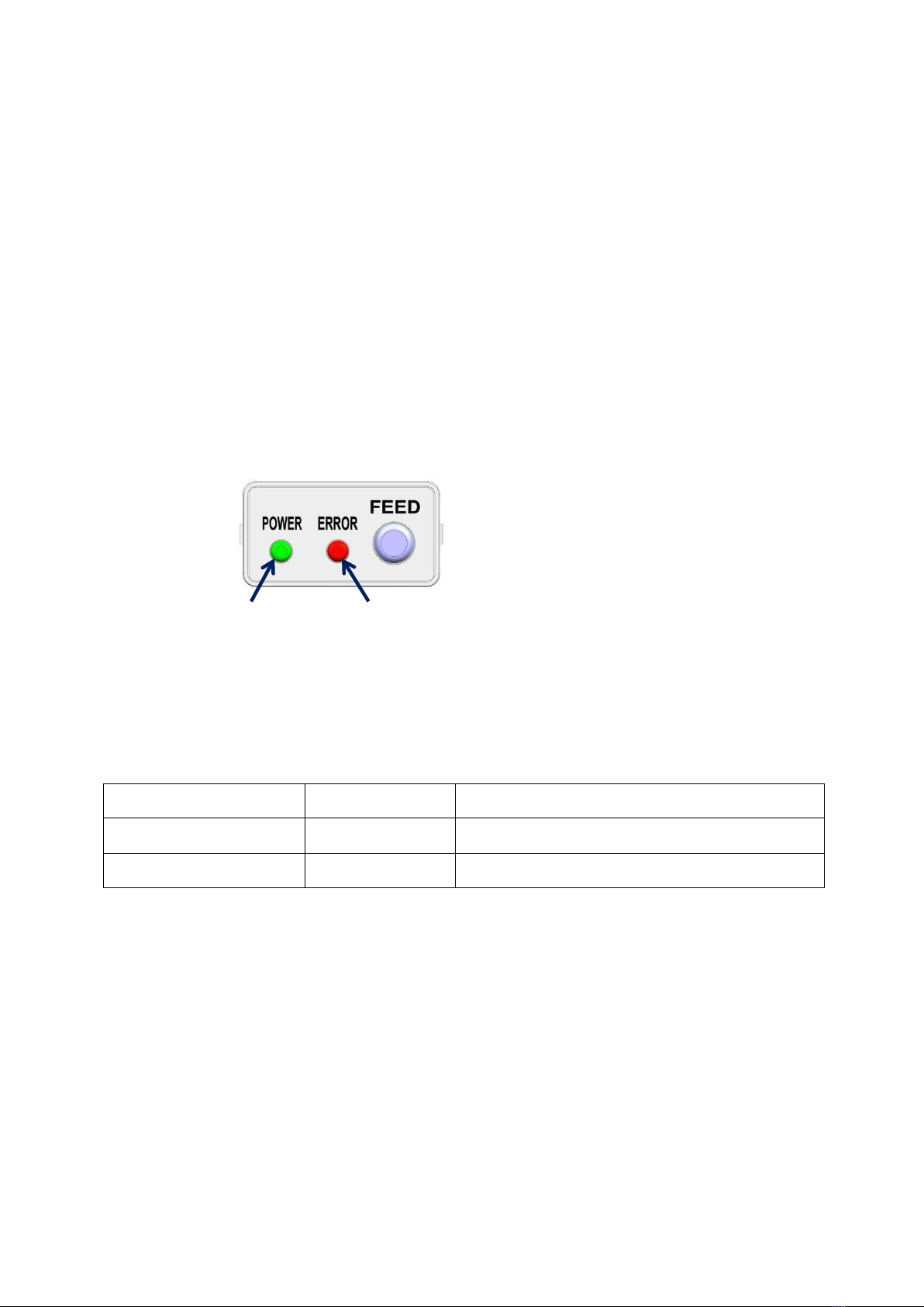
1. Power Switch/Paper Feed Button and Status Notification Indicator........................................... 8
1) Power Switch .......................................................................................................................................................................8
2) Paper Feed Button............................................................................................................................................................8
3) Status Notification Lights ..............................................................................................................................................9
2. Detect Sensors...................................................................................................................................... 10
1) Cover Open Sensor ....................................................................................................................................................... 10
2) Paper Detect Sensor ..................................................................................................................................................... 10
3) Black Mark Sensor ......................................................................................................................................................... 11
4) Cutter Home Sensor ..................................................................................................................................................... 11
5) Near End(Paper Low) Sensor .................................................................................................................................... 11
6) Adjustable GAP Sensor (OPTION) .......................................................................................................................... 11
7) Presenter Control Sensor (OPTION) ...................................................................................................................... 11
3. PRESENTER (OPTION) ......................................................................................................................... 12
1) Loop Function.................................................................................................................................................................. 12
2) Eject Function................................................................................................................................................................... 12
3) Hold Function .................................................................................................................................................................. 13
4) Automatic Retract(Dispose) Function ................................................................................................................... 13
5) Presenter Jam removal method............................................................................................................................... 14
4. Adjustable Guide & Sensor Function (OPTION) ............................................................................ 15
1) Paper width adjustment method............................................................................................................................ 15
2) Gap Sensor / Black mark Sensor (Gap Detection Sensor / Black mark Detection Sensor) ........ 15
3) Black mark Sensor setting method ....................................................................................................................... 16
4) GAP Sensor position setting method................................................................................................................... 17
www.compodis.com

5
Ⅲ. PRINTER USE GUIDE .......................................................................................................................... 18
1. Power port connection method ........................................................................................................ 18
2. Interface connection............................................................................................................................ 19
3. Paper Change........................................................................................................................................ 20
1) Cover open method...................................................................................................................................................... 20
2) Auto Loading Method ................................................................................................................................................. 21
4. Self Test.................................................................................................................................................. 22
5. HEX Dump Print ................................................................................................................................... 23
Ⅳ. PRINTER INSTALLATION METHOD.................................................................................................. 24
1. Example of Printer installation method .......................................................................................... 24
1) Method by making Hook shapes on the Top side and mounting the Printer................................. 24
2) Method by using Mount Brackets for fixing and mounting the Printer.............................................. 25
3) Method by mounting in the floor (BOTTOM) side ..................................................................................... 26
2. Large sized paper holder installation method(OPTION).............................................................. 27
1) Assembling the paper holder................................................................................................................................... 27
2) Connecting the Near End Sensor connector .................................................................................................... 27
3. Electrostatic discharge and ground current handling .................................................................. 28
Ⅴ. PRINTER FUNCTION SETTINGS ....................................................................................................... 29
1. Setting Manually .................................................................................................................................. 29
2. Set Using Memory Switch Program ................................................................................................. 31
3. Firmware Update.................................................................................................................................. 33
4. Ethernet Interface Settings ................................................................................................................ 34
5. Ticket Paper Settings........................................................................................................................... 37
www.compodis.com

6
Ⅵ. PRODUCT SPECIFICATIONS .............................................................................................................. 38
1. Printer Specifications .......................................................................................................................... 38
2. Presenter Specifications...................................................................................................................... 40
3. Interface Specifications....................................................................................................................... 41
1) USB........................................................................................................................................................................................ 41
2) Serial (RS-232C) .............................................................................................................................................................. 42
3) Ethernet .............................................................................................................................................................................. 43
Ⅶ. PRODUCT APPEARANCE AND DIMENSIONS ................................................................................ 44
1. HMK-830(A)B........................................................................................................................................ 44
2. HMK-830(A)PB ..................................................................................................................................... 44
3. HMK-830(A) .......................................................................................................................................... 46
4. HMK-830(A)P........................................................................................................................................ 48
Ⅷ. COMMAND SPECIFICATIONS ........................................................................................................... 50
www.compodis.com

7
Ⅰ. Printer Features
HMK-830 series printers are designed to be used by installing or connecting to Kiosk Systems.
This printer uses direct thermal printing method and the paper width can be set to suit user‟s
environment. Also, with HMK-830 Series Printers, both of Roll type paper and Fan Folder type
paper can be used.
1. Printer Features
Thermal Head
Cover Open Lever
Presenter Unit
Auto Cutter
Feed Button / Status Notification Light(LED)
Power Switch
Paper Roll Holder
Paper Holder Fixture
Paper Holder Shaft
Power Port
Ethernet
Port
Serial Port
USB Port
Near End Sensor
Connector
www.compodis.com

8
Ⅱ. Main Functions
1. Power Switch/Paper Feed Button and Status Notification
Indicator
1) Power Switch
The power switch is used to turn the power on or off, and it is also used for self test and
changing printer status settings.
2) Paper Feed Button
The FEED button can perform the following functions.
Paper feed button
Paper feed button and status notification light
Power switch
www.compodis.com

9
① Paper feed: When paper is inserted, pressing the feed button feeds paper for as long as the
button is pressed.
② Self Test: While holding the FEED button, turn on the power and then release the button after
the Error light turns on once. The self test contents will then be printed. (Refer to the description
of the Ⅲ. PRINTER USE GUIDE)
③ Checking and changing the printer status: If you turn on the power while holding the FEED
button, the Error light flashes continuously. When the button is released at this time, the printer
status menu is printed. (Refer to the description of the Ⅴ. PRINTER FUNCTION SETTINGS)
3) Status Notification Lights
① Power light: When the power is turned on, the green power light turns on.
② Error light: Depending on the printer status, the light blinks to inform you of the printer status
as shown below.
Notification light status
Notification sound
Printer status
Flashing briefly
Beep (short)
No paper
Long flashing
Beeeep (long)
Cover open, cutter jammed, paper jammed, etc.
Error light(Error notification light)
Power light
www.compodis.com

10
2. Detect Sensors
Several detection sensors placed on the printer transmit the printer's status to the host system..
1) Cover Open Sensor
The cover open switch detects when the cover is open and stops the printing and ticket feeding
process until the cover is closed.
2) Paper Detect Sensor
A sensor that detects the presence and absence of paper, used to control paper insertion and
printing, as well as notifications to notify the user to reload paper.
Cover Open Sensor
GAP Sensor
Paper Detect Sensor
Black Mark Sensor
Near End (Paper Low) Sensor
Cutter Home Sensor
Presenter Control Sensor
www.compodis.com

11
3) Black Mark Sensor
It is used to control the starting point of printing by detecting the black mark position.
4) Cutter Home Sensor
The cutter sensor is used to detect if the paper has been cut.
5) Near End(Paper Low) Sensor
The Near End(Paper Low) Sensor(Paper shortage detection sensor) is a detection sensor that
automatically informs the user when to change paper..
6) Adjustable GAP Sensor (OPTION)
When using label paper, it controls the printing position of the label paper by detecting the gap
or black mark position between the label and the label.
7) Presenter Control Sensor (OPTION)
A sensor that detects the start and end of the paper so that the presenter can control the paper.
www.compodis.com

12
3. PRESENTER (OPTION)
When the presenter function is added, receipt handling becomes easy and the following functions
can be used.
1) Loop Function
If the length of the printout is longer than a certain level, this function keeps the paper in the
middle until printing is finished. Users can only take the contents after printing is complete,
ensuring safety.
2) Eject Function
When printing is finished, the ticket or receipt is released out of the machine. When printing
multiple tickets in a row, it is arranged in the order in which they were printed. (Ticket holder sold
separately)
Paper loop status
Stack printed Tickets
www.compodis.com

13
3) Hold Function
Function of the presenter holding the paper until the user takes the printed ticket or receipt.
4) Automatic Retract(Dispose) Function
If the user does not take the printed ticket or receipt after a certain period of time, it is the
function to collect and discard the printed material into the designated device or space.
Automatic disposal of untaken ticket
Discarded into designated device or space
Printed Ticket
www.compodis.com

14
5) Presenter Jam removal method
If a paper jam occurs in the presenter, raise the Cover open roller in the direction of the
arrow to open it, remove the paper, and close the Cover open roller again.
www.compodis.com

15
4. Adjustable Guide & Sensor Function (OPTION)
With the Adjustable(movable) Guide & Sensor option, you can adjust the position of the paper
guides and sensors to set the paper width as you need.
1) Paper width adjustment method
Set the Adjustable Paper Guide in the left and right direction of the arrow to match the width of
the paper to be used. (Adjustment range: 25mm ~ 82.5mm)
2) Gap Sensor / Black mark Sensor (Gap Detection Sensor / Black mark
Detection Sensor)
The Adjustable Guide & Sensor type product can be used as a gap sensor or a black mark sensor,
and can be used by moving the sensor position to the required position.
Adjustable Paper Guide
www.compodis.com

16
3) Black mark Sensor setting method
Set by moving the black mark sensor holder to the left and right of the arrow according to the
position of the black mark on the paper.
If necessary, it can be adjusted by referring to the position display scale at the bottom.
Black mark sensor holder
www.compodis.com

17
4) GAP Sensor position setting method
① Adjustment of the position of the gap sensor in the image below is the same as Adjustment of
the black mark sensor, so adjust the same as the black mark sensor setting method.
② Press the cover open lever to open the cover.
③ To adjust the position of the gap sensor located on the upper cover, adjust the gap sensor
holder in the direction of the arrow so that the position matches with the gap sensor at the
bottom (using a tool such as tweezers).
If the position of GAP Sensor is not aligned with position of the black mark detection
sensor at the bottom, the sensor sensitivity may decrease as much as it is not aligned. In that
case, gap detection may not be possible, so make sure to align them.
Gap sensor holder
CAUTION
www.compodis.com

18
Ⅲ. Printer Use Guide
1. Power port connection method
When connecting power, be sure to connect the power cable to the power port while the power
switch turned off.
①2 hole power cable connection
②3 hole power cable connection
The rated power of this product is 24V, so do not use a power supply that is out of
specification. It may cause product failure or safety accident.
Please use only the power supply provided by our company for the power supply.
Be sure to connect according to the instructions in the manual.
Power port
Power cable
Power cable
Power port
CAUTION
WARNING
www.compodis.com

19
2. Interface connection
Use an interface cable that meets the specifications of the host.
When connecting a communication cable, be sure to that the power switch is turned off.
Ethernet Port
Serial Port
USB Port
CAUTION
②
①
③
④
www.compodis.com
Other manuals for COMPODIS HMK-830 Series
1
This manual suits for next models
3
Table of contents
Other Hwasung Folding Machine manuals