HWH SPACEMAKER User manual

OPERATOR’S MANUAL
05FEB07
ML40087/MP04.0281
AP40086
www.hwh.com
Ph: 800/321-3494 (or) 563/724-3396 | Fax: 563/724-3408
2096 Moscow Road | Moscow, Iowa 52760
(On I-80, Exit 267 South)
HWH CORPORATION
FEATURING:
Single / Multiple Room Extensions / Generator Slide
CORPORATION
W
HH
R
HWH HYDRAULIC SPACEMAKER
ROOM EXTENSION SYSTEMS
R
CORPORATION
W
CLEAR OF ROOM WHEN OPERATING.
UNDERSTAND OPERATOR’S MANUAL BEFORE
USING. KEEP PEOPLE AND OBSTRUCTIONS
HYDRAULIC ROOM EXTENSION
H
OFF
CAUTION!
ON
H
EXTEND
RETRACT
R
CORPORATION
W
CLEAR OF ROOM WHEN OPERATING.
UNDERSTAND OPERATOR’S MANUAL BEFORE
USING. KEEP PEOPLE AND OBSTRUCTIONS
HYDRAULIC ROOM EXTENSION
H
OFF
CAUTION!
ON
H
EXTEND
RETRACT
R
RR

CAUTION !
READ THE ENTIRE OPERATOR’S MANUAL BEFORE OPERATING.
CAUSING INJURY OR DEATH.
CHIPS, OIL LEAKS, ETC. FOLLOW ALL OTHER APPLICABLE SHOP SAFETY PRACTICES.
OPERATOR’S MANUAL
MP14.0000
05FEB07
NEVER PLACE HANDS OR OTHER PARTS OF THE BODY NEAR HYDRAULIC LEAKS. OIL MAY PENETRATE SKIN
WEAR SAFETY GLASSES WHEN INSPECTING OR SERVICING THE SYSTEM TO PROTECT EYES FROM DIRT, METAL
KEEP PEOPLE AND OBSTRUCTIONS CLEAR OF ROOM WHEN OPERATING. ANY OBJECT OBSTRUCTING ROOM
MOVEMENT MAY BE CRUSHED CAUSING INJURY OR DEATH AND VEHICLE DAMAGE.
HOW TO OBTAIN WARRANTY SERVICE
THIS IS NOT TO BE INTERPRETED AS A STATEMENT OF WARRANTY
HWH CORPORATION strives to maintain the highest level of
customer satisfaction. Therefore, if you discover a defect or
problem, please do the following:
(563) 724-3396 OR (800) 321-3494. Give your name and
coach was purchased, or the date of system installation,
Notify the dealership where you purchased the
vehicle or had the leveling system installed. Dealership
management people are in the best position to resolve
the problem quickly. If the dealer has difficulty solving
the problem, he should immediately contact the Customer
Service Department, at HWH CORPORATION.
If your dealer cannot or will not solve the problem,
notify the Customer Service Department:
HWH CORPORATION 2096 Moscow Rd. Moscow IA. 52760
address, coach manufacturer and model year, date the
SECOND:
FIRST:
authorization of an independent service facility, to be
defective part, either by appointment at the factory or by the
CORPORATION will authorize repair or replacement of the
determine whether or not your claim is valid. If it is, HWH
HWH CORPORATION personnel will contact you to
during business hours (8:00 a.m. till 5:00 p.m. c.s.t.).
description of the problem, and where you can be reached
determined by HWH CORPORATION. All warranty repairs
must be performed by an independent service facility
authorized by HWH CORPORATION, or at the
HWH CORPORATION factory, unless prior written approval
has been obtained from proper HWH CORPORATION
personnel.

CONTROL FUNCTIONS
CONTROL IDENTIFICATION
MP24.4560
05FEB07
CORPORATION
H
CAUTION!
CLEAR OF ROOM WHEN OPERATING.
UNDERSTAND OPERATOR’S MANUAL BEFORE
USING. KEEP PEOPLE AND OBSTRUCTIONS
HYDRAULIC ROOM EXTENSION
OFF
ON
RETRACT
H
W
R
EXTEND ROOM CONTROL
SWITCH
KEY SWITCH
The KEY SWITCH controls power to the ROOM
CONTROL SWITCH. When the KEY SWITCH is in the "ON"
POSITION the room can be operated, and the key cannot be
removed. When the KEY SWITCH is in the "OFF" position
the room cannot be operated, and the key can be removed.
The ROOM CONTROL SWITCH
is a two position momentary switch. Pressing the switch in
the EXTEND POSITION will extend the room. Pressing the
switch in the RETRACT POSITION will retract the room. Re-
leasing the ROOM CONTROL SWITCH will halt the operation
of the room.
ROOM OPERATOR’S PANEL
KEY
KEY SWITCH: ROOM CONTROL SWITCH:
is OEM provided. Refer to OEM operator instructions.
This switch (not shown)ROOM SELECTOR SWITCH:
OEM PROVIDED ROOM SELECTOR SWITCH (IF APPLICABLE)

OPERATING PROCEDURES
MP34.0200
07FEB07
GENERAL INSTRUCTIONS
PREPARATION FOR TRAVEL
If the rooms cannot be retracted according to the
ROOM RETRACT Section, retract the rooms according
to the MANUAL ROOM RETRACTION Section.
The system should then be checked.
The room systems or generator slide should be cycled
once a month or whenever the vehicle is used, to keep
the system in operating condition.
Maintain adequate clearance in all directions for vehicle, room
extensions, awnings, doors, steps, etc. Vehicle may move in
any direction due to jacks extending or retracting, settling of
the jacks or the vehicle, equipment malfunction, etc..
Any room extension or generator slide should be fully
THE VEHICLE SHOULD NOT BE MOVED
IF ONE OR MORE ROOMS OR THE GENERATOR SLIDE
CAUTION:
retracted before traveling.
IMPORTANT: This manual covers different mechanism styles and arrangements If a room is not an HWH
mechanism, refer to the correct operator’s manual for operating instructions. This manual also covers rooms
and slides on motorized or non-motorized vehicles. The operating instructions contained in this manual covers
the most common situations. Non-motorized vehicles will not depend on an ignition switch or park brake, but
there may be a master power switch for the system.
NOTE: If the vehicle is equipped with an HWH 225 series joystick leveling system, the on light on the leveling
system panel MAY have to be on to operate a room extension.
ARE EXTENDED.
by HWH. Refer to the vehicle or clamp/lock manufacturer for correct operating instructions.
NOTE: Some rooms may be equipped with travel clamps/locks that are NOT supplied

OPERATING PROCEDURES
ROOM EXTEND PROCEDURE FOR ROOMS
2. Follow applicable LEVELING AND STABILIZING
3. Unlock all room-locking devices to include travel
the room remove it before extending the room.
WARNING:
extend the room.
6. To extend the room, press and hold the
ROOM CONTROL SWITCH in the "EXTEND" position
until the room is fully extended.
halt the operation of the room.
7. Turn the room control panel KEY SWITCH to
8. Turn off the ignition switch, if applicable.
KEEP PEOPLE AND OBSTRUCTIONS
CLEAR OF ROOM WHEN OPERATING.
4. Turn the ignition switch to ACCESSORY or turn
IMPORTANT: Do not use a room extension support
when the vehicle is supported by the leveling system.
NOTE: If the MANUAL RETRACT WINCH is attached to
NOTE: Make sure there is adequate clearance to fully
NOTE: Releasing the ROOM CONTROL SWITCH will
5. Turn the room control panel KEY SWITCH to
the "ON" position.
after the room is fully extended or stops moving.
in the "EXTEND" position for more than ten seconds
of the room, do not reverse direction of the room until
after the room is fully extended. This assures proper
Hold the switch to "EXTEND" three or four seconds
pressurization of the cylinders.
Do not hold the ROOM CONTROL SWITCHIMPORTANT:
NOTE:
During normal operation
the room is fully extended. If necessary, the direction
of the room may be reversed, but watch for binding of
the room. If the direction of the room has been
reversed, DO NOT re-extend the room until the room
has been fully retracted.
If either side of the room stops moving, release the
room control switch immediately. DO NOT force the
room. DO NOT reverse direction of the room, contact
HWH Customer Service for assistance 1-800-321-3494.
1. The park brake must be set for motorized vehicles.
The room will not operate if the park brake is not set.
MP34.4300
24SEP07
the "OFF" position.
It is recommended to retract room extensions before
DISENGAGED BEFORE OPERATING THE ROOM.
RETRACTING DEVICES ARE DETACHED OR
ALL ROOM LOCKING, CLAMPING OR MANUAL
OPERATOR’S RESPONSIBILITY TO ENSURE THAT
PERSONAL INJURY AND VEHICLE DAMAGE. IT IS THE
DEVICES ATTACHED OR ENGAGED CAN CAUSE
ROOM LOCKING, CLAMPING OR MANUAL RETRACTING
Leveling Procedure before operating room extensions.
NOTE: It is recommended to complete any applicable
retracting a leveling system.
WARNING: OPERATING A ROOM WITH ANY
PROCEDURES.
a MASTER POWER SWITCH on, if applicable.
clamps/locks supplied by manufacturers other than HWH.
WITHOUT TRAVEL CLAMPS

OPERATING PROCEDURES
NOTE: It is recommended to retract room extensions
before retracting a leveling system.
3. Turn the room control panel KEY SWITCH to
4. To retract the room press and hold the
ROOM CONTROL SWITCH in the "RETRACT" position
until the room is fully retracted.
halt the operation of the room.
5. Turn the room control panel KEY SWITCH to
6. Turn the ignition switch off, if applicable.
IMPORTANT: Room-locking devices should be locked
while traveling.
WARNING:
CLEAR OF ROOM WHEN OPERATING.
KEEP PEOPLE AND OBSTRUCTIONS
7. If the room will not retract see the MANUAL ROOM
RETRACT PROCEDURE.
NOTE: Releasing the ROOM CONTROL SWITCH will
HWH Customer Service for assistance 1-800-321-3494.
room. DO NOT reverse direction of the room, contact
room control switch immediately. DO NOT force the
If either side of the room stops moving, release the
after the room is fully retracted or stops moving.
in the "RETRACT" position for more than ten seconds
Do not hold the ROOM CONTROL SWITCH
reversed, DO NOT retract the room until the room
the room. If the direction of the room has been
of the room may be reversed, but watch for binding of
the room is fully retracted. If necessary, the direction
of the room, do not reverse direction of the room until
During normal operation
Hold the switch to "RETRACT" three or four seconds
after the room is fully retracted. This assures proper
has been fully extended.
pressurization of the cylinders.
IMPORTANT:
NOTE:
MP34.4500
24SEP07
1. The park brake must be set, if applicable.
The room will not operate if the park brake is not set.
the "ON" position. the "OFF" position.
a MASTER POWER SWITCH on, if applicable.
2. Turn the ignition switch to ACCESSORY or turn
WITHOUT TRAVEL CLAMPS
ROOM RETRACT PROCEDURE FOR ROOMS

OPERATING PROCEDURES
MP34.6100
07FEB07
GENERATOR SLIDE EXTEND PROCEDURE
CAUTION:
CLEAR OF SLIDE WHEN OPERATING.
NOTE: Make sure there is adequate clearance
to fully extend the slide.
3. To extend the slide, press and hold the GENERATOR
SLIDE CONTROL SWITCH in the "EXTEND" position.
When the slide is fully extended, release the GENERATOR
SLIDE CONTROL SWITCH.
IMPORTANT: Do not hold the GENERATOR SLIDE
CONTROL SWITCH in the "EXTEND" position for more
than ten seconds after the slide is fully extended or
NOTE: Releasing the GENERATOR SLIDE CONTROL
SWITCH will halt the operation of the slide.
GENERATOR SLIDE RETRACT PROCEDURE
3. To retract the slide, press and hold the GENERATOR
SLIDE CONTROL SWITCH in the "RETRACT" position.
When the slide is fully retracted, release the GENERATOR
SLIDE CONTROL SWITCH.
KEEP PEOPLE AND OBSTRUCTIONS
2. THE PARK BRAKE MUST BE SET FOR THE SLIDE TO
OPERATE IF ON A MOTORIZED VEHICLE.
1. Turn the ignition key on, if applicable.
IN THE EVENT OF FAILURE OF THE GENERATOR SLIDE
TO RETRACT, REFER TO THE MANAUAL ROOM AND
GENERATOR SLIDE RETRACT PROCEDURES OR
CONTACT HWH CORPORATION CUSTOMER SERVICE
2. THE PARK BRAKE MUST BE SET FOR THE SLIDE TO
OPERATE IF ON A MOTORIZED VEHICLE.
1. Turn the ignition key on, if applicable.
stops moving.
than ten seconds after the slide is fully retracted or
CONTROL SWITCH in the "RETRACT" position for more
IMPORTANT: Do not hold the GENERATOR SLIDE
stops moving.
SWITCH will halt the operation of the slide.
NOTE: Releasing the GENERATOR SLIDE CONTROL
AT 1-319-724-3396 OR 1-800-321-3494 FOR ASSISTANCE.

MP34.9500
07FEB07
MANUAL ROOM AND GENERATOR SLIDE RETRACT PROCEDURE
OVERVIEW
1. Retract jacks following the LEVELING SYSTEM
RETRACT PROCEDURE.
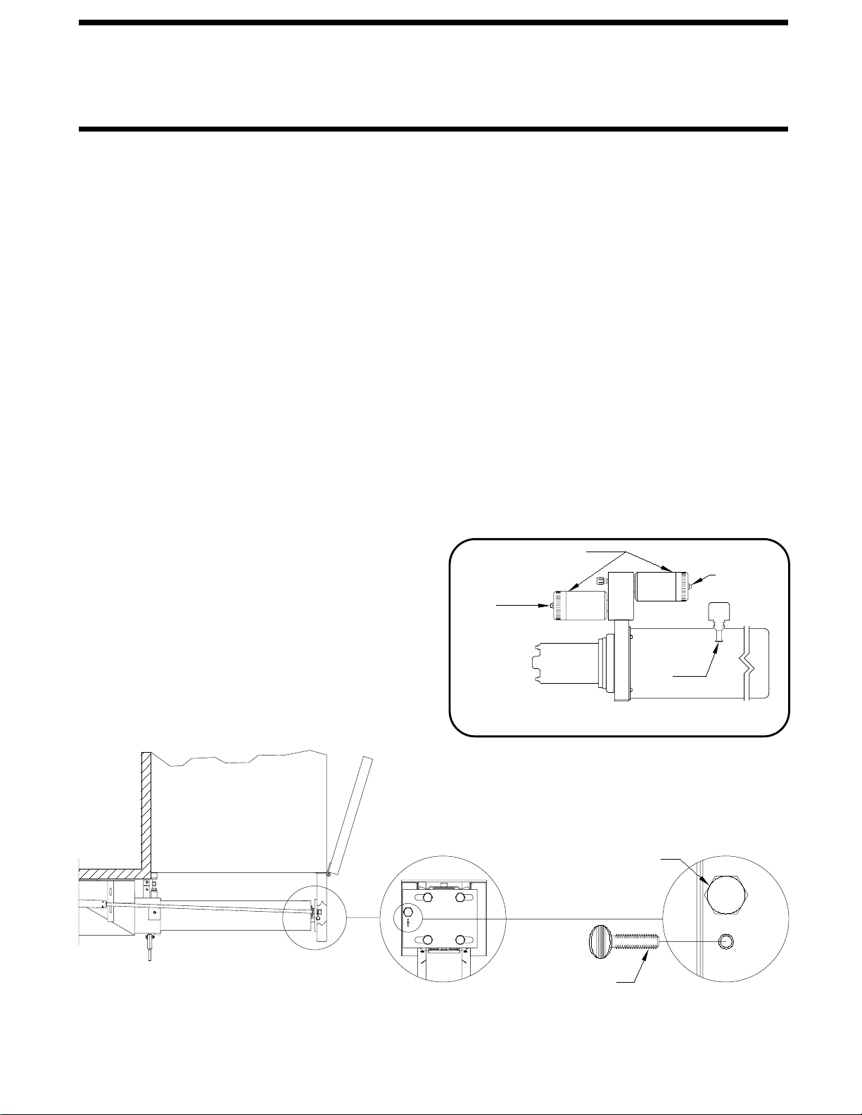
2. Locate the HYDRAULIC PUMP/MANIFOLD unit.
VALVES are opened and internal pressure is released.
WINCH
WINCH STRAP
WINCH HANDLE
RATCHET LEVER
HOOK
MANUAL RETRACT WINCH
5. Slowly winch the room in by turning the WINCH HANDLE
clockwise. The RATCHET LEVER should produce a loud, sharp,
clicking noise.
in the hydraulic fluid and make winching more difficult.
CAUTION:
ON
OFF
HYDRAULIC PUMP/MANIFOLD
NOTE: The room may move slightly as the SOLENOID
NOTE :
NOTE: Winching the room in quickly will raise pressure
IMPORTANT:
6. When the room is fully retracted, engage the room locking
devices. Leave the retract winch engaged and the solenoid
CAUTION: THE ROOM EXTENSION SOLENOID
VALVE RELEASE NUTS MUST BE IN THE OPEN
POSITION WHEN THE MANUAL RETRACT WINCH IS
7. The system should be repaired before using again.
CAUTION: THE MANUAL RETRACT WINCH IS
OPERATE THE MANUAL RETRACT
WINCH BY HAND POWER ONLY. IF THE WINCH
CANNOT BE CRANKED EASILY WITH ONE HAND IT IS
PROBABLY OVERLOADED. IF WINCHING BECOMES
TOO DIFFICULT STOP AND CHECK FOR OBSTRUCTIONS
OR RESTRICTIONS ON THE ROOM AND ROOM
LEVELING SYSTEM MANIFOLD NOT SHOWN
SOLENOID VALVES
VALVE
RELEASE
NUT NUT
VALVE
RELEASE
3. Open the Solenoid Valves by slowly turning the valve
release nuts counter clockwise using the 1/4" nut driver
Only open the valves enough to retract NOTE: After repairs are made, when
closing the VALVE RELEASE NUTS, do
When manually retracting the room, make sure
the jacks are retracted before retracting the room.
EQUIPPED FOR MANUALLY RETRACTING THE ROOM
ONLY. IT IS NOT TO BE USED FOR LIFTING OR ANY
OTHER APPLICATION. HIGH FORCES ARE CREATED
WHEN USING A WINCH, CREATING POTENTIAL SAFETY
HAZARDS. FAILURE TO FOLLOW ALL CAUTIONS AND
INSTRUCTIONS MAY CAUSE FAILURE OF THE MANUAL
RETRACT WINCH OR CONNECTIONS RESULTING IN
DAMAGE OR PERSONAL INJURY. MAINTAIN FIRM GRIP
ON THE WINCH HANDLE AT ALL TIMES. NEVER
RELEASE THE HANDLE WHEN RATCHET LEVER IS IN
THE OFF POSITION AND THE WINCH IS LOADED. THE
WINCH HANDLE COULD SPIN VIOLENTLY AND CAUSE
PERSONAL INJURY. CHECK THE WINCH AND STRAPS
FOR DAMAGE OR WEAR, AND CHECK FOR PROPER
RATCHET OPERATION ON EACH USE OF THE WINCH.
DO NOT USE IF DAMAGED OR WORN.
supplied.
the room. DO NOT turn the release nuts more than
4 and 1/2 turns. Turning the nuts more could damage
the valves.
with the Operators Manual. As of APRIL 2002 the
NOTE: Prior to APRIL 2002 a 1/4" Nut Driver was sent
Cap. See the back page of this manual for further info.
1/4" Nut Driver has been incorporated into the Breather
4. Locate the MANUAL RETRACT WINCH and connect
it to the room according to the vehicle manufacturer’s
instructions. To extend the WINCH STRAP firmly grasp
WINCH HANDLE, place RATCHET LEVER in its OFF
position, and slowly rotate the WINCH HANDLE
counter clockwise, keeping a firm grip on the handle. When
enough WINCH STRAP is extended, place the RATCHET
LEVER in its ON position and slowly rotate the WINCH
HANDLE clockwise until the RATCHET LEVER locks.
EXTENSION MECHANISM.
valves open.
ENGAGED.
(WITH SOLENOID VALVES WITH VALVE RELEASE NUTS)
(USE ONLY WHEN THE ROOM WILL NOT RETRACT WITH THE ROOM CONTROL SWITCH)
not over tighten the nuts.
IMPORTANT: If the vehicle is not equipped with a winch,
DO NOT use other pulling devices to retract the room.
Follow steps 2 and 3 and try pushing the room in.
Contact the vehicle manufacturer or HWH Customer
Service at 1-800-321-3494 or 563-724-3396 for assistance.
The room can be retracted manually if a hydraulic or electric
failure prevents the room from being retracted using the
CONTROL SWITCH. For normal retract sequence see the
ROOM SLIDE RETRACT PROCEDURES. Refer to the
vehicle manufacturer for storage location of the winch
and information for connecting the winch to the room.

"LEVEL-OUT" (ANGLE MOUNT) ROOM EXTENSION MECHANISM
MANUAL ROOM RETRACTION PROCEDURES
Manual Retraction Bolt
Thumb Screw
5. Replace both Thumb Screws.
MP34.9550
07FEB07
OPERATING PROCEDURES
DO NOT over tighten.
IMPORTANT: If at any stage something is not
understood or if the room begins to bind DO NOT force
the room, contact HWH Customer Service for assistance
1-800-321-3494.
8. Replace both Thumb Screws. Leave the manual valve
releases open.
7. Repeat steps 4 and 5 alternating from mechanism to
mechanism rotating each Manual Retraction Bolt 12
complete turns until room is sealed. (DO NOT exceed 15
ft.lbs) Make sure the room does not bind.
6. Return to the first room extension mechanism and rotate
the Manual Retraction Bolt clockwise 12 complete turns.
5. Move to the second room extension mechanism, rotate
the Manual Retraction Bolt clockwise 12 complete turns.
4. Using wrench provided, a personal wrench or a tire iron
with a 13/16" or 21mm opening rotate either mechanism’s
Manual Retraction Bolt clockwise 6 complete turns.
3. Remove the Thumb Screws (one on each mechanism)
completely by turning them counterclockwise.
2. Gain access to the 13/16" Manual Retraction Bolts (one
on each mechanism) by raising the STORE-MORE access
panel.
1. Determine which extend and retract solenoid valves are
assigned to the room. Manually open the valve release nuts
for the extend and retract solenoid valves by turning the 1/4"
release nuts counter clockwise 4 and 1/2 turns. Turning the
6. Close both manual valve releases assigned to the
room. Turn the valve release nuts clockwise until snug.
4. Move to the second room extension mechanism and
repeat step 3.
3. If needed, using wrench provided, a personal wrench or
a tire iron with a 13/16" or 21mm opening rotate either
mechanism’s Manual Retraction Bolt counterclockwise until
resistance is met.
2. Remove the Thumb Screws (one on each mechanism)
completely by turning them counterclockwise.
1. Gain access to the 13/16" Manual Retraction Bolts (one
on each mechanism) by raising the STORE-MORE access
panel.
IMPORTANT: DO NOT EXTEND THE ROOM
UNTIL THE STEPS BELOW HAVE BEEN
COMPLETED!
SOLENOID VALVES
LEVELING SYSTEM MANIFOLD NOT SHOWN
HYDRAULIC PUMP/MANIFOLD
nuts more could damage the valves.
NOTE: The breather cap dip stick is also a 1/4" nut driver.
VALVE
RELEASE
NUT
VALVE
RELEASE
NUT
BREATHER
CAP-DIP
STICK
Actual Mounting May Differ

"LEVEL-OUT" ROOM EXTENSION MECHANISM
MANUAL ROOM RETRACTION PROCEDURES
Manual Retraction Bolt
Thumb Screw
5. Replace both Thumb Screws.
MP34.9552
07FEB07
OPERATING PROCEDURES
DO NOT over tighten.
IMPORTANT: If at any stage something is not
understood or if the room begins to bind DO NOT force
the room, contact HWH Customer Service for assistance
1-800-321-3494.
8. Replace both Thumb Screws. Leave the manual valve
releases open.
7. Repeat steps 4 and 5 alternating from mechanism to
mechanism rotating each Manual Retraction Bolt 12
complete turns until room is sealed. (DO NOT exceed 15
ft.lbs) Make sure the room does not bind.
6. Return to the first room extension mechanism and rotate
the Manual Retraction Bolt clockwise 12 complete turns.
5. Move to the second room extension mechanism, rotate
the Manual Retraction Bolt clockwise 12 complete turns.
4. Using wrench provided, a personal wrench or a tire iron
with a 13/16" or 21mm opening rotate either mechanism’s
Manual Retraction Bolt clockwise 6 complete turns.
3. Remove the Thumb Screws (one on each mechanism)
completely by turning them counterclockwise.
2. Gain access to the 13/16" Manual Retraction Bolts (one
on each mechanism) by raising the STORE-MORE access
panel.
1. Determine which extend and retract solenoid valves are
assigned to the room. Manually open the valve release nuts
for the extend and retract solenoid valves by turning the 1/4"
release nuts counter clockwise 4 and 1/2 turns. Turning the
6. Close both manual valve releases assigned to the
room. Turn the valve release nuts clockwise until snug.
4. Move to the second room extension mechanism and
repeat step 3.
3. If needed, using wrench provided, a personal wrench or
a tire iron with a 13/16" or 21mm opening rotate either
mechanism’s Manual Retraction Bolt counterclockwise until
resistance is met.
2. Remove the Thumb Screws (one on each mechanism)
completely by turning them counterclockwise.
1. Gain access to the 13/16" Manual Retraction Bolts (one
on each mechanism) by raising the STORE-MORE access
panel.
IMPORTANT: DO NOT EXTEND THE ROOM
UNTIL THE STEPS BELOW HAVE BEEN
COMPLETED!
SOLENOID VALVES
LEVELING SYSTEM MANIFOLD NOT SHOWN
HYDRAULIC PUMP/MANIFOLD
nuts more could damage the valves.
NOTE: The breather cap dip stick is also a 1/4" nut driver.
VALVE
RELEASE
NUT
VALVE
RELEASE
NUT
BREATHER
CAP-DIP
STICK

"X-SLIDE" ROOM EXTENSION MECHANISM
MANUAL ROOM RETRACTION PROCEDURES
MP34.9554
07FEB07
OPERATING PROCEDURES
1. Determine which extend and retract solenoid valves are
assigned to the room. Manually open the valve release nuts
for the extend and retract solenoid valves by turning the 1/4"
release nuts counter clockwise 4 and 1/2 turns. Turning the
SOLENOID VALVES
LEVELING SYSTEM MANIFOLD NOT SHOWN
HYDRAULIC PUMP/MANIFOLD
nuts more could damage the valves.
NOTE: The breather cap dip stick is also a 1/4" nut driver.
VALVE
RELEASE
NUT
VALVE
RELEASE
NUT
BREATHER
CAP-DIP
STICK
THREADED
BLOCK
RECEIVER
PLATE
ROOM EXTENDED ROOM RETRACTED
THREADED
BLOCK
ROD
THREADED
RECEIVER
PLATE
ROD
THREADED
2. Start both threaded rods until resistance is met, one for
the front and one for the rear mechanism should be provided.
NOTE: To access the threaded blocks refer to vehicle
manufacturer. threaded rods completely, alternate backing the
threaded rods out and slightly extending the room.
Be careful to not extend the room so far that the
threaded rods impact the coach wall or the mechanism.
RODS SHOULD BE COMPLETELY REMOVED.
LEFT OPEN SHOULD BE CLOSED AND THE THREADED
ROOM HAS BEEN SERVICED. ANY SOLENOID VALVES
NOTE: Leave the solenoid valves open and the
threaded rods in place until the room has been
6. Repeat steps 4 and 5 alternating from mechanism to
the threaded rod clockwise 12 complete turns.
turns until room is sealed. (DO NOT exceed 15
IMPORTANT: DO NOT EXTEND THE ROOM UNTIL THE
mechanism rotating each threaded rod 12 complete
IMPORTANT: If at any stage something is not
understood or if the room begins to bind DO NOT force
the room, contact HWH Customer Service for assistance
5. Return to the first room extension mechanism and rotate
NOTE: If there is not enough room to remove both
the threaded rod clockwise 12 complete turns.
4. Move to the other room extension mechanism, rotate
ft.lbs) Make sure the room does not bind.
serviced.
1-800-321-3494.
opening rotate either mechanism’s threaded rod clockwise
provided, a personal wrench or a tire iron with a 1-1/8"
Do Not use an impact wrench.
6 complete turns.
3. Using wrench

"UNIVERSAL STRAIGHT OUT" ROOM EXTENSION MECHANISM
MANUAL ROOM RETRACTION PROCEDURES
MP34.9556
07FEB07
OPERATING PROCEDURES
PLATE
RECEIVER
ROD
THREADED
ROOM EXTENDED
THREADED
BLOCK
ROOM RETRACTED
BLOCK
THREADED
THREADED
ROD
manufacturer.
the front and one for the rear mechanism should be provided.
2. Start both threaded rods until resistance is met, one for
SOLENOID VALVES
HYDRAULIC PUMP/MANIFOLD
LEVELING SYSTEM MANIFOLD NOT SHOWN
NOTE: The breather cap dip stick is also a 1/4" nut driver.
NOTE: To access the threaded blocks refer to vehicle
nuts more could damage the valves.
release nuts counter clockwise 4 and 1/2 turns. Turning the
for the extend and retract solenoid valves by turning the 1/4"
assigned to the room. Manually open the valve release nuts
1. Determine which extend and retract solenoid valves are
NUT
RELEASE
VALVE
CAP-DIP
BREATHER
STICK
RELEASE
VALVE
NUT
4. Move to the other room extension mechanism, rotate
the room, contact HWH Customer Service for assistance
understood or if the room begins to bind DO NOT force
IMPORTANT: If at any stage something is not
6. Repeat steps 4 and 5 alternating from mechanism to
mechanism rotating each threaded rod 12 complete
turns until room is sealed. (DO NOT exceed 15
5. Return to the first room extension mechanism and rotate
the threaded rod clockwise 12 complete turns.
ft.lbs) Make sure the room does not bind.
1-800-321-3494.
Do Not use an impact wrench.
either mechanism’s threaded rod clockwise 6 complete turns.
a personal wrench or a tire iron with a 1-1/8" opening rotate
3. Using wrench provided, threaded rods impact the coach wall or the mechanism.
Be careful to not extend the room so far that the
threaded rods out and slightly extending the room.
threaded rods completely, alternate backing the
NOTE: If there is not enough room to remove both
ROOM HAS BEEN SERVICED. ANY SOLENOID VALVES
RODS SHOULD BE COMPLETELY REMOVED.
LEFT OPEN SHOULD BE CLOSED AND THE THREADED
IMPORTANT: DO NOT EXTEND THE ROOM UNTIL THE
threaded rods in place until the room has been
NOTE: Leave the solenoid valves open and the
serviced.

"UNIVERSAL STRAIGHT OUT" ROOM EXTENSION MECHANISM
MANUAL ROOM RETRACTION PROCEDURES
MP34.9558
07FEB07
OPERATING PROCEDURES
PLATE
RECEIVER
ROD
THREADED
ROOM EXTENDED
THREADED
BLOCK
ROOM RETRACTED
BLOCK
THREADED
THREADED
ROD
manufacturer.
the front and one for the rear mechanism should be provided.
2. Start both threaded rods until resistance is met, one for
HYDRAULIC PUMP/MANIFOLD
NOTE: The breather cap dip stick is also a 1/4" nut driver.
NOTE: To access the threaded blocks refer to vehicle
nuts more could damage the valves.
release nuts counter clockwise 4 and 1/2 turns. Turning the
for the extend and retract solenoid valves by turning the 1/4"
assigned to the room. Manually open the valve release nuts
1. Determine which extend and retract solenoid valves are
NUT
RELEASE
VALVE RELEASE
VALVE
NUT
4. Move to the other room extension mechanism, rotate
the room, contact HWH Customer Service for assistance
understood or if the room begins to bind DO NOT force
IMPORTANT: If at any stage something is not
6. Repeat steps 4 and 5 alternating from mechanism to
mechanism rotating each threaded rod 12 complete
turns until room is sealed. (DO NOT exceed 15
5. Return to the first room extension mechanism and rotate
the threaded rod clockwise 12 complete turns.
ft.lbs) Make sure the room does not bind.
1-800-321-3494.
Do Not use an impact wrench.
either mechanism’s threaded rod clockwise 6 complete turns.
a personal wrench or a tire iron with a 1-1/8" opening rotate
3. Using wrench provided, threaded rods impact the coach wall or the mechanism.
Be careful to not extend the room so far that the
threaded rods out and slightly extending the room.
threaded rods completely, alternate backing the
NOTE: If there is not enough room to remove both
ROOM HAS BEEN SERVICED. ANY SOLENOID VALVES
RODS SHOULD BE COMPLETELY REMOVED.
LEFT OPEN SHOULD BE CLOSED AND THE THREADED
IMPORTANT: DO NOT EXTEND THE ROOM UNTIL THE
threaded rods in place until the room has been
NOTE: Leave the solenoid valves open and the
serviced.
BREATHER
STICK
CAP-DIP
SOLENOID VALVES

"UNIVERSAL LEVEL OUT" ROOM EXTENSION MECHANISM
MANUAL ROOM LIFT PROCEDURES
MP34.9560
07FEB07
OPERATING PROCEDURES
SOLENOID VALVES
HYDRAULIC PUMP/MANIFOLD
LEVELING SYSTEM MANIFOLD NOT SHOWN
NOTE: The breather cap dip stick is also a 1/4" nut driver.
nuts more could damage the valves.
release nuts counter clockwise 4 and 1/2 turns. Turning the
for the extend and retract solenoid valves by turning the 1/4"
assigned to the room. Manually open the valve release nuts
1. Determine which extend and retract solenoid valves are
NUT
RELEASE
VALVE
CAP-DIP
BREATHER
STICK
RELEASE
VALVE
NUT
BOTTOM
GAP
SURFACE
LIFT BOLT
LIFT RAMP
LIFT BOLT
Using a 9/16 wrench
alternate between lift bolts turning each 4 full turns each
the front and one for the rear mechanism should be provided.
2. Start both room lift bolts until resistance is met, one for
NOTE: To locate the room lift access holes
refer to vehicle manufacturer.
Do Not use an impact wrench.
the room, contact HWH Customer Service for assistance
understood or if the room begins to bind DO NOT force
IMPORTANT: If at any stage something is not
1-800-321-3494.
NOTE: Manual room lift procedures must be done before
manual room retraction procedures.
As the
room is lifted a gap should develop allowing you to
time. Lift the room only as far as is needed to clear the
bottom surface of the room over the lift ramps.
OF ROOM
3.
view the lift ramps more clearly.
4. Follow MANUAL ROOM RETRACT PROCEDURES.
(ML36687/MP35.956D)
EXTERIOR
COACH
WALL
EXTERIOR
WALL
COACH
END VIEW OF
ROOM EXTENDED
END VIEW OF
ROOM EXTENDED

"UNIVERSAL LEVEL OUT" ROOM EXTENSION MECHANISM
MANUAL ROOM RETRACT PROCEDURES
MP34.9561
07FEB07
OPERATING PROCEDURES
PLATE
RECEIVER
ROOM EXTENDED
ROOM RETRACTED
BLOCK
TREADED
manufacturer.
Using wrench provided,
a personal wrench or a tire iron with a 1-1/8" opening rotate
either mechanism’s threaded rod clockwise 6 complete turns.
the front and one for the rear mechanism should be provided.
1. Start both threaded rods until resistance is met, one for
NOTE: To access the threaded blocks refer to vehicle
3. Move to the other room extension mechanism, rotate
the room, contact HWH Customer Service for assistance
ROOM HAS BEEN SERVICED. ANY SOLENOID VALVES
IMPORTANT: DO NOT EXTEND THE ROOM UNTIL THE
understood or if the room begins to bind DO NOT force
IMPORTANT: If at any stage something is not
5. Repeat steps 3 and 4 alternating from mechanism to
mechanism rotating each threaded rod 12 complete
turns until room is sealed. (DO NOT exceed 15
4. Return to the first room extension mechanism and rotate
the threaded rod clockwise 12 complete turns.
ft.lbs) Make sure the room does not bind.
1-800-321-3494.
Do Not use an impact wrench.
THREADED
ROD
BLOCK
THREADED
ROD
THREADED
NOTE: Manual room lift procedures must be done before
manual room retraction procedures.
2.
NOTE: Leave the solenoid valves open, the lift bolts
and threaded rods in place until the room has been
serviced.
EXTERIOR
WALL
COACH
END VIEW OF
ROOM EXTENDED
END VIEW OF
ROOM RETRACTED
WALL
COACH
EXTERIOR
LEFT OPEN SHOULD BE CLOSED, LIFT BOLTS AND
THREADED RODS SHOULD BE COMPLETELY
REMOVED.
NOTE: If there is not enough room to remove both
threaded rods completely, alternate backing the
threaded rods out and slightly extending the room.
Be careful to not extend the room so far that the
threaded rods impact the coach wall or the mechanism.

BREATHER CAP - DIPSTICK - 1/4" NUT DRIVER
MP84.9999
07FEB07
VALVE RELEASE
NUT 1 1/2" DIAMETER
SOLENOID VALVE
NOTE: DO NOT turn the valve
release nut more than 4 and 1/2
(four and one half) turns counter
clockwise. Damage to the valve
may result.
OIL LEVEL
BREATHER CAP
OIL LEVEL GROOVES
1/4" NUT DRIVER
NOTE: THE BREATHER CAP IS LOCATED
ON THE TOP SIDE OF THE POWER UNIT RESERVOIR.
IMPORTANT: PRIOR TO REMOVING THE BREATHER CAP,
EITHER TO CHECK THE OIL LEVEL OR TO USE THE 1/4" NUT DRIVER,
CLEAN ANY DEBRIS FROM THE TOP OF THE RESERVOIR.
INCLUDING DEBRIS INSIDE THE 1/4" NUT DRIVER.
REMOVE ANY PAINT CHIPS OR OTHER DEBRIS FROM THE DIPSTICK
BEFORE RETURNING THE BREATHER CAP TO THE RESERVOIR,
VALVE RELEASE
NUT
to the valve may result.
turn counter clockwise. Damage
NOTE: DO NOT turn the valve
release nut more than 1 full
PLASTIC PLUG
REMOVE TO
GAIN ACCESS
TO THE 1/4"
VALVE RELEASE
NUT
SOLENOID VALVE
2 1/4" DIAMETER
Other manuals for SPACEMAKER
2
Table of contents
Popular Door Opening System manuals by other brands

SIMONSWERK
SIMONSWERK Anselmi AN 140 3D ALU installation instructions

Dormakaba
Dormakaba ED900 owner's manual

Entrematic Group
Entrematic Group Ditec PASAA2 Operation manual

BEA
BEA Gyrotech 1100 Wiring diagrams

DITEC
DITEC OLLY C Installation and maintenance manual

Rittal
Rittal VX IT 7030.262 Assembly and operating instructions