OPTIONAL
KITS:
HEAVY-DUTY
LOWER
MAST
SUPPORT
KIT
(51467-10)
(Optional)
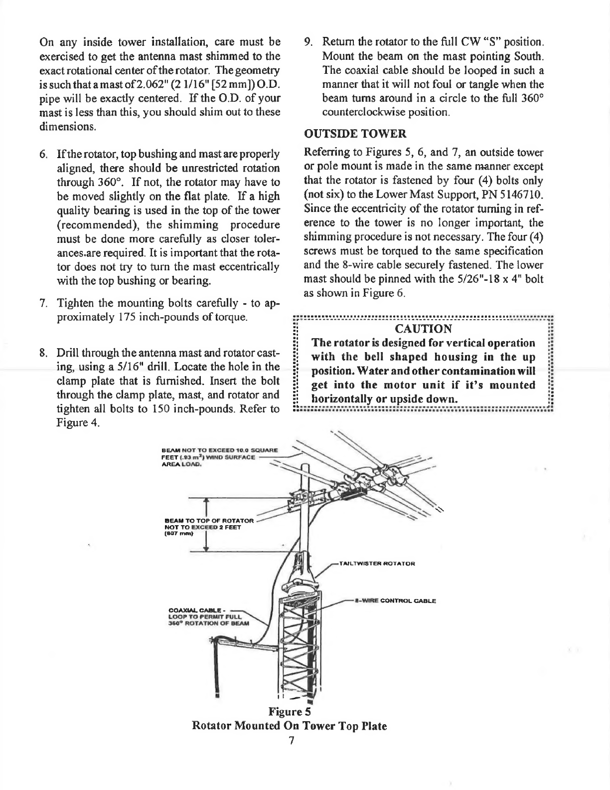
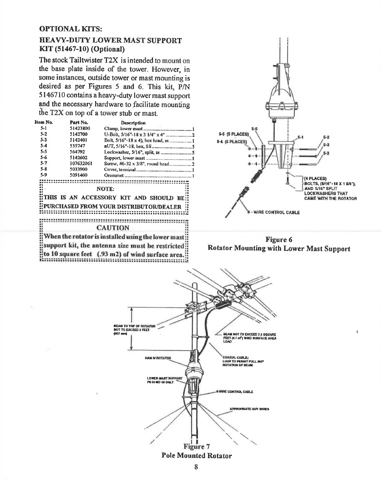
The
stock
Tailtwister
T2X
is
intended
to
mount
on
the
base
plate
inside
of
the
tower.
However,
in
some
instances,
outside
tower
or
mast
mounting
is
desired
as
per
Figures
5
and
6.
This
kit,
P/N
5146710
contains
a
heavy-duty
lower
mast
support
and
the
necessary
hardware
to
facilitate
mounting
the
T2X
on
top
of
a
tower
stub
or
mast.
Item
No,
Part
No.
Description
5-1
51423800
Clamp,
lower
mast
...,..,..00
peteatts
ie
ies
ds
1
56
5-2
5142700
U-Bolt,
5/16"-18
x3
1/4"
x4"...
a2
5-5
(5
PLACES)
5-2
5-3
5142401
Bolt,
5/16"-18
x
4),
hex
head,
ss.
wl
54
(5
PLACES)
/
53
5-4
555747
AUT,
5/16"-18,
hex,
SS
oo.
L5
yh.
=
$-5
564792
Lockwasher,
5/16",
split,
ss
...
iS
beans
BS
5-2
5-6
5142602
Support,
lower
MaSt
.cccseeecec--
wl
aie
.
ae
5-7
107632061
Screw,
46-32
x
3/8",
round
head.
3
$-4-
5-8
5033900
Cover,
terminal...
wal
$-9
5091400
Grommet
.........
oe
|
(4
PLACES)
Go
cces
ssc
ca
eee
nan
CeB
Eee
Ree
ee
Ree
eee
eee
ec
eee
esesesacsass
BOLTs,
es
-18X
1
6/8°),
ee
AND
5/16"
SPLIT
2
NOTE
LOCKWASHERS
THAT
i
THIS
IS
AN
ACCESSORY
KIT
AND
SHOULD
BE!
CAME
WITH
THE
ROTATOR
PURCHASED
FROM
YOUR
DISTRIBUTOR/DEALER
|:
wf
-
WIRE
CONTAOL
CABLE
i
CAUTION
i
?}
When
the
rotator
is
installed
using
the
lower
mast}:
i
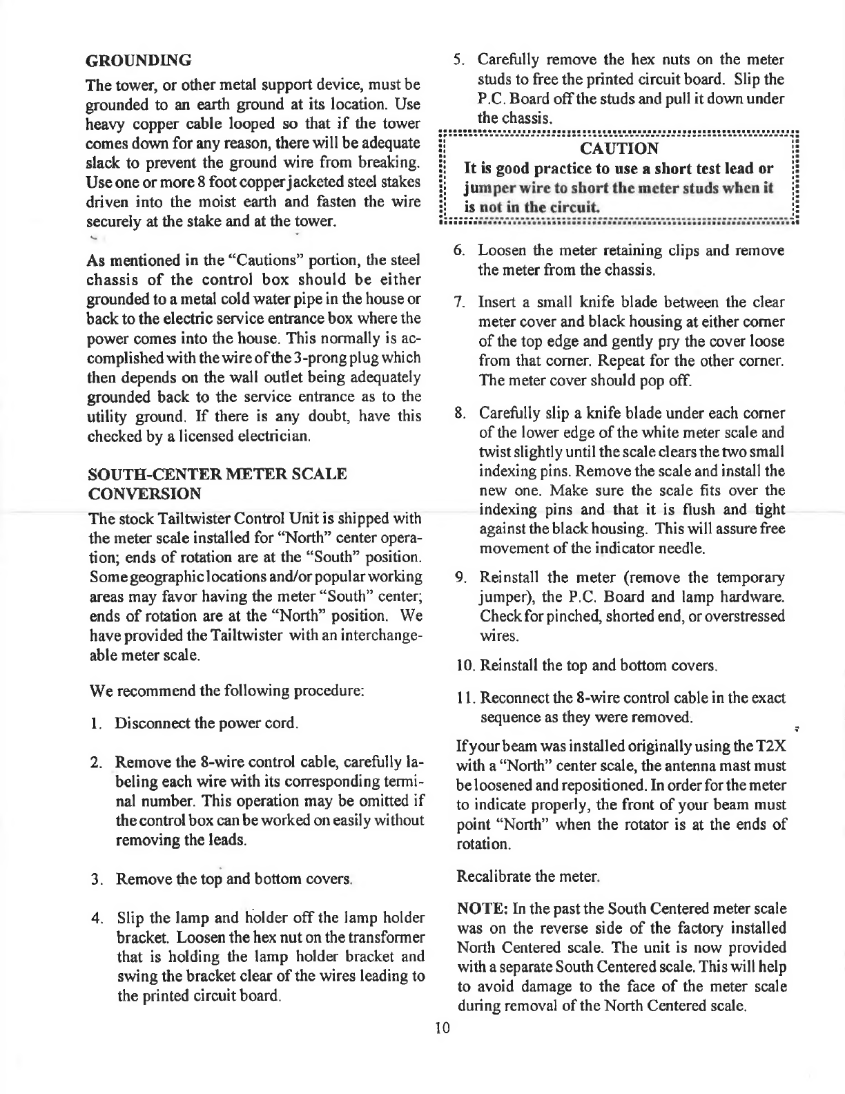
Figure
6
i
support
kit,
the
antenna
size
must
be
restricted?
Rotator
Mounting
with
Lower
Mast
Support
Hto
10
square
feet
(.93
m2)
of
wind
surface
area.:
ee
OSSBSSsSSsssessssscssssscccecsnssassescsesseseeeeeeceeeeeeeleaed
7
"
Sis
&
ae
ne
by
SSi
gi
|
a
oe
sai)
a
»
in
BEAN
TO
TOP
OF
ROTATOR
~
NOT
TO
EXCEED
2
FEET
(007
mm)
=
BEAM
NOT
TO
EXCEED
7.6
GQUARE
—>
FEET
(0.7
mo?)
WIND
SURFACE
AREA
|
ae
LOAD
HAM
WEARER
Va
i
toon
to
penne
FULL
36a°
ROTATION
OF
BEAM
-y
LOWER
MAST
SUPPORT
\aerp
PN
61467-10
ONLY
i
/\L
G-WIRE
CONTROL
CABLE
J—3—|}
Co
KF
APPROPRIATE
QUY
WIRES:
we
a.
SS
4
J
\
SS
Figure
7
Pole
Mounted
Rotator
8