manuals.online logo
Brands
  1. Home
  2. •
  3. Brands
  4. •
  5. Hy-Gain
  6. •
  7. Measuring Instrument
  8. •
  9. Hy-Gain 421A Owner's manual

Hy-Gain 421A Owner's manual

ORDER NO.,
421A
The Power Meter is a high quality, compact, easy to in-
stall instrument. It will measure the VSWR of an antenna
directly on the meter without an inter-pol ation chart,
percentage of modul ation to over 100% and power output
in 3 ranges up to 500 W.
The Power Meter was designed for maximum operating
convenience and as such consists of two parts. The
modern style Indicator unit can be placed In a convenient
position while the Sensor, which is placed in the line
between the transceiver and the antenna, can stand or
hang behind the transceiver. This alleviates the need to
run coaxial cables across the operating desk. The Indi~
cator and Sensor units are hooked together with the inter-
connection cable suppl ied.
Hei ght. ,
3"
Width
7"
Depth ....•.•... " 5 1/8':
Net Weight , , . 1 1/2 Ibs.
Construction Lightweight aluminum chassis with
rugged steel case ..
Total Shipping Weight.. , .. , , .. 3 1/4 Ibs.
Impedance 50 Ohms Input and Output
Connector Data Sensor and Indicator hooked
together with 4 foot cable supplied
Power Ranges Three power ranges from 0 to
10,100 and 500 watts
Modulation Measures percentage of
modulation to over·100%
VSWR , . '" : Measures VSWR of antenna
Frequency Range , , ....•. 3- 60 MHz
() Carefully remove the Indicator and Sensor units from
the packing carton. Examine it closely for signs of ship-
ping damage. *See last paragraphs in this manual.
() Connect the Sensor unit between the Transceiver and
antenna, being careful to connect the coaxial connector
on the short length of coaxial cable to the output of the
Transceiver. Connect the antenna to the SO-239 socket
on the Sensor.
Assuming that the Power Meter has been installed as out-
Iined above, proceed as follows to measure the VSWRof
the antenna. Rotate the Ca librate control full y co~nter-
INSlAlLAI'IO;N'
o
PERAllO N INSTRUCTIONS
. H,{~GAtA
ELECTRONics
CORPORATION'
4
fturat
Route
3
l.incoln:
Ne6raska·6'S5Q5: '~
• '~", "",,"~ , ..•' I, ,', , -\'
'@~
cfockwi se, switch the Function ?witch to FWD (forward),
key the Transceiver and adv(1)Ce the Cal ibrate control
unti I the meter reads full scal e(jus.i to the end of the
cal ibrated scales, nofurther). Switch the. Function Switch
to SWR and the VSWR of theantennaca.n .be read directly
from the SWRscale. Unkey the Transceiver.
Before measuring the percentage of modulation, check the
VSWR of the antenna as outl ined abOve. The VSWR should
be less than 1.5 to 1 for the percentage of modulation to
be correct (it will indicate modulation with a higher VSWR
but not accuratel y).
Set Function Switch to FWD, Cal ibrate full counter-clock-
wise, key the Transceiver. Advance the Calibrate control
to full sr.al e defl ection ,swi tch the Function' Switch to
MOD. Talking or whistling into the microphone witl now
give a percentage of modulation on the meter. Adjust the
distance between the microphone and the mouth so that
on words Iike "five" the percentage of [nodulation does
not exceed 100%. Unkey the Transceiver.
The Power Meter Will measure,'uslng.three ranges, the
power output
Uf)
to'500 watts. The VSWR should be less
than 1 b to 1 for thiS rneasurementto be accurate.
When measuring the pnwpr output always start on the high-
est range (500w) and then go down until
8
reading is ob-
tained, do not let the meter be pinned full scale. The
Cal ibrate control does not operate in the power position.
The Power Meter power scales are a factory adjustment
internally and should not be adjusted.
DO NOT ship equipment to the Manufacturer without prior
authori zation. We prefer to send spec iaI shippi ng Iabe Is
whi ch wi II avo id the del ay of unexpected shipment.
If time is extremely important, wire or call for approval
and we will rush labels to you. When a shipment is ex-
pected, even the time of sending the labels is less than
that lost when an unexpected shipment is received.
It is VERY IMPORTANT that the shipment be well packed
and fully insured. Damage claims must be settled between
you and the carrier and will greatly delay any returns.
Proper packing normally avoids this trouble.
ALL SHIPMENTS MUST BE SENT TO US PREPAID. I'Vedo not
accept collect shipments. All returns should.be made in
our standard cartons only - so save your carton when un-
pacting the unit. When a shipment is returned it will be
handled in one of three ways ...
1.---Whereall service is in warranty the shipment will
be returned with transportation costs collected by the
carrier on arrival.
2.---lf there are any charges not covered by warranty, we
wi.11 hold the shipment and advise you of costs which you
can then send. The shipment will arrive with only trans-
portation costs collected by the carrier on arrival.
3. - - - Or upon your written authori zation, we wi II ship
C.O. D. fo r any cha rgesnot covered by wa rranty; then the
carrier will collect these charges, and the transportation
costs on arrival. Unci aimed or refused C.O. D. shipments
will not be reshipped until payment of service and trans-
portation charges is received. Shipment will then be made
collect for reshipment transportation charges. Unclaimed
equipment automatically becomes the property of the
Manufacturer 60 days after date of refusal or return and
will be disposed of for payment of charges due.
We WILL NOT ship by means of a carrier that will not fully
insure the shipment. Some carriers have a
$200.00
limit.
The exception to this is when there is no other means
APO-FPO-etc.) of shipment than parcel post, and then we
will ship by this means with your written agreement that
you assume any loss over that which the carrier will in-
sure. C.O.D. shipments cannot be made to APO-FPO
addresses.
All replacement parts orders must be prepaid or C.O. D.
only.
Replacement part price quotes will be furnished on request
for those who desire prepaid shipment or cannot accept
C.O. D. shipments.
Hy-Gain Electronics Corporation warranty each new pro-
duct manufactured to be free from defects in materi al and
workmanship and agrees to remedy any such defect, or to
furnish a new part, in exchange for any part of any unit
which under normal installation, use. and service dis-
closes such defect within ninety days from the date of
purchase by original owner.
This warranty does not extend to any of our products
which have been subjected to mi Souse. neglect. accident,
incorrect wiring not our own. improper installation or to
use in violation of instructions furnished by us. Nor does
it extend to units which have been repaired or altered out-
side of our factory nor to accessories used therewith not
of our own manufacture.
Hy-Gain Electronics Corporation reserves· the right to
make any changes deemed necessary or desirable without
advance notice or incurring any obligation to make like
changes in units previously manufactured or sold.
This warranty does not cover transportation or install ation
costs that may be incurred. Hy-Gain Electronics Corpora-
tion's sole liability is remedy of any defect for ninety
days. Hy-Gain Electronics Corporation is not responsibl e
for personal injury or property damage resulting from i
proper or careless insta: I ation or usage not intended b"
the manufacturer.
No person is authorized to assume for us any other lia-
bility in connection with the sale of our products.
A II warranti es are voi d and termi nated one year after th
i'
last unit of its type and design has been manufactured b\
us.
Hy-Gain Electronics Corporation
Attention: Customer Service Department
R.R. #3
Lincoln, Nebraska 68505
You must furni sh model number. date, place and proof of
purchase, such as a copy of the sales receipt to establ ish
warranty. Your letter should include all pertinent details
(Jlong with part or item numbers involved. Do Not return
anything until requested to do so. No warranty card is
furnished. You must supply the above information.
Any returned items must have prior authorization. Unex-
pected returns are greatly delayed in handling. These
delays can be avoided by writing in advance furnishing
the above information.
ALIGNMENT:
All internal adjustments of the :l21A were made atth·
factory prior to shipment. The accuracy of the meter
IS
dependent upon the adjustment of these control s and do
not require any further adjustment. No attempt should be
made to disturb the settings unless precision test equip-
ment is used. If internal adjustments are to be attempted
the following test equipment must be used.
A 50 ohm resistive dummy load capable of 500 watts con-
tinuous duty, an accurate RF voltmeter equivalent to the
Hewlett Packard 410-B or 410-C, a transmitter with varia-
ble output to at least 500 watts on 30 MHz. and an insu
lated al ignment tool.
Remove the covers from the indicator and sensor units.
Connect the short Iength of cabl e from the sensor unit lC
the transmitter. Using a piece of coaxial 50 ohm cabl e,
connect the dummy load to the S0-239 socket on the
sensor.
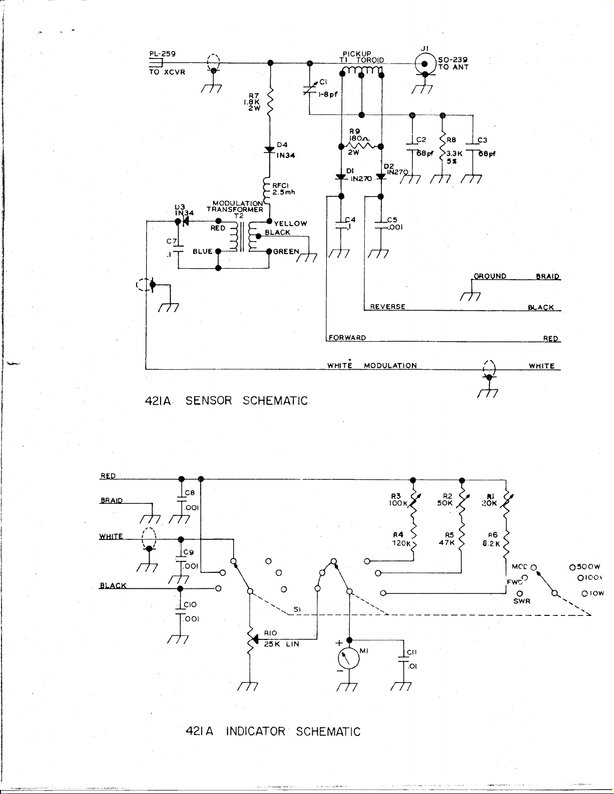
Switch the indicator unit to FWD, key the transmitter and
adjust the Cal ibrate control for full scale, switch to SV\JR
and if any reflected power is present. adjust the pistoll
trimmer, in the sensor. for a minimum. Un key.
POWER ADJUSTMENT: .
Switch the 421A to the 10 watt position. With the RF vol
t
meter connected across the dummy load. apply power and
increase it until exactly 22 voltsRrv1S is across the ioacl.
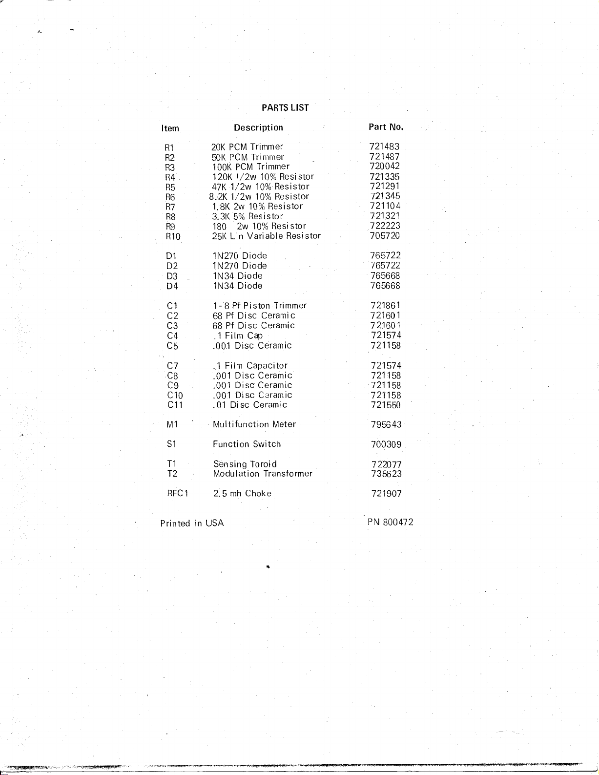
Adjust the small trimmer pot (R1). see reverse side
(if
circuit board. so that the 421A reads exactly 10 watts.
Switch to the 100 watt range and increase power until the
volt meter reads 70 volts RMS. Adjust the center pot (R2)
until the 421A reads 100 watts.
Swi tc.h to the 500 watt range and increase the power unti
i
the volt meter reads 158 volts RMS. Adjust the trimmer
pot (R3) unti I the 421A reads 500 watts.
PARTS LIST
Item Description Part No.
R1 20K PCM Trimmer 721483
R2 50K PCM Trimmer 721487
R3 lOOK PCM Trimmer 720042
R4 120K Il2w 10% Resi stor 721335
R5 47K 112w 10% Resistor 721291
R6 8.,2K 1/2w 10% Resistor 721345
R7 1.8K 2w 10% Resistor 721104
R8 3.3K 5% Resistor 721321
R9 180 2w 10% Resi stor 722223
Rl0 25K Lin Variable Resistor 705720
01 lN270 Diode 765722
02 lN270 Diode 765722
03 lN34 Diode 765668
04 lN34 Diode 765668
C1 1-8 Pf Piston Trimmer 721861
C2 68 Pf Disc Ceramic 721601
C3 68 Pf Disc Ceramic 721601
C4 .1 Film Cap 721574
C5 .001 Disc Ceramic 721158
C7 .,1 Film Capacitor 721574
C8 .001 Disc Ceramic 721158
C9 .001 Disc Ceramic 721158
Cl0 .001 Disc C8ramic 721158
Cll .01 Disc Ceramic 721550
Ml Multifunction Meter 795643
Sl Function Switch 700309
Tl Sensing Toroid 722077
T2 Modulation Transformer 735623
RFCl 2.5 mh Choke 721907
Printed in USA PN 800472
"
I ,
Ii
~
1Jlc~g~
tJJL_~JI SO-23g
TO ANT
CI
I-Spf
r+;0UND
BRAID
REVERSE BLA K
FORWARD R
.
/"\
WHITE MODULATION
I )
WHITE
;+;
R3
R2
RJ
lOOK
50K
201<
R R5
120K)
47K
rh.
; ;01
ooo
MC'C0 0500W
FWC,O
0100,
o
I
0 ~
o10W
, SWR "
,,
- ---------------------
RIO
25 K L1N

Other Hy-Gain Measuring Instrument manuals

Hy-Gain RBD-5 User manual

Hy-Gain

Hy-Gain RBD-5 User manual

Hy-Gain TAILTWISTER T-2X User manual

Hy-Gain

Hy-Gain TAILTWISTER T-2X User manual

Popular Measuring Instrument manuals by other brands

Leica RANGEMASTER 1200 scan Specifications

Leica

Leica RANGEMASTER 1200 scan Specifications

Idexx Coag Dx Quick reference guide

Idexx

Idexx Coag Dx Quick reference guide

Audioscope 3000 operating instructions

Audioscope

Audioscope 3000 operating instructions

GE Centricity SP1001 user manual

GE

GE Centricity SP1001 user manual

Aiwa CSD-ES577 Service manual

Aiwa

Aiwa CSD-ES577 Service manual

Graco FX250 Instructions-parts list

Graco

Graco FX250 Instructions-parts list

Teledyne Lecroy DXC100A Operator's manual

Teledyne Lecroy

Teledyne Lecroy DXC100A Operator's manual

Endress+Hauser Cerabar S PMC71 technical information

Endress+Hauser

Endress+Hauser Cerabar S PMC71 technical information

Fike FAAST XT 68-302 Installation and maintenance instructions

Fike

Fike FAAST XT 68-302 Installation and maintenance instructions

Eagle Tree Systems Pro user manual

Eagle Tree Systems

Eagle Tree Systems Pro user manual

Lutron Electronics EMF-819 Operation manuals

Lutron Electronics

Lutron Electronics EMF-819 Operation manuals

Delmhorst F-2000T Operation manual

Delmhorst

Delmhorst F-2000T Operation manual

ARENDO 304908 manual

ARENDO

ARENDO 304908 manual

Hanna Instruments HI 86301 instruction manual

Hanna Instruments

Hanna Instruments HI 86301 instruction manual

LOVATO ELECTRIC LOVATO ELECTRIC installation manual

LOVATO ELECTRIC

LOVATO ELECTRIC LOVATO ELECTRIC installation manual

Spectrasensors 2000 Series Operator's manual

Spectrasensors

Spectrasensors 2000 Series Operator's manual

Health Metric TDS & EC METER 2.0 user manual

Health Metric

Health Metric TDS & EC METER 2.0 user manual

Ludlum Measurements 12SA manual

Ludlum Measurements

Ludlum Measurements 12SA manual

manuals.online logo
manuals.online logoBrands
  • About & Mission
  • Contact us
  • Privacy Policy
  • Terms and Conditions

Copyright 2025 Manuals.Online. All Rights Reserved.