Date Printed: 07/11/2011 “Commercial-in-Confidence” Page Number: 8
Hyden Engineering
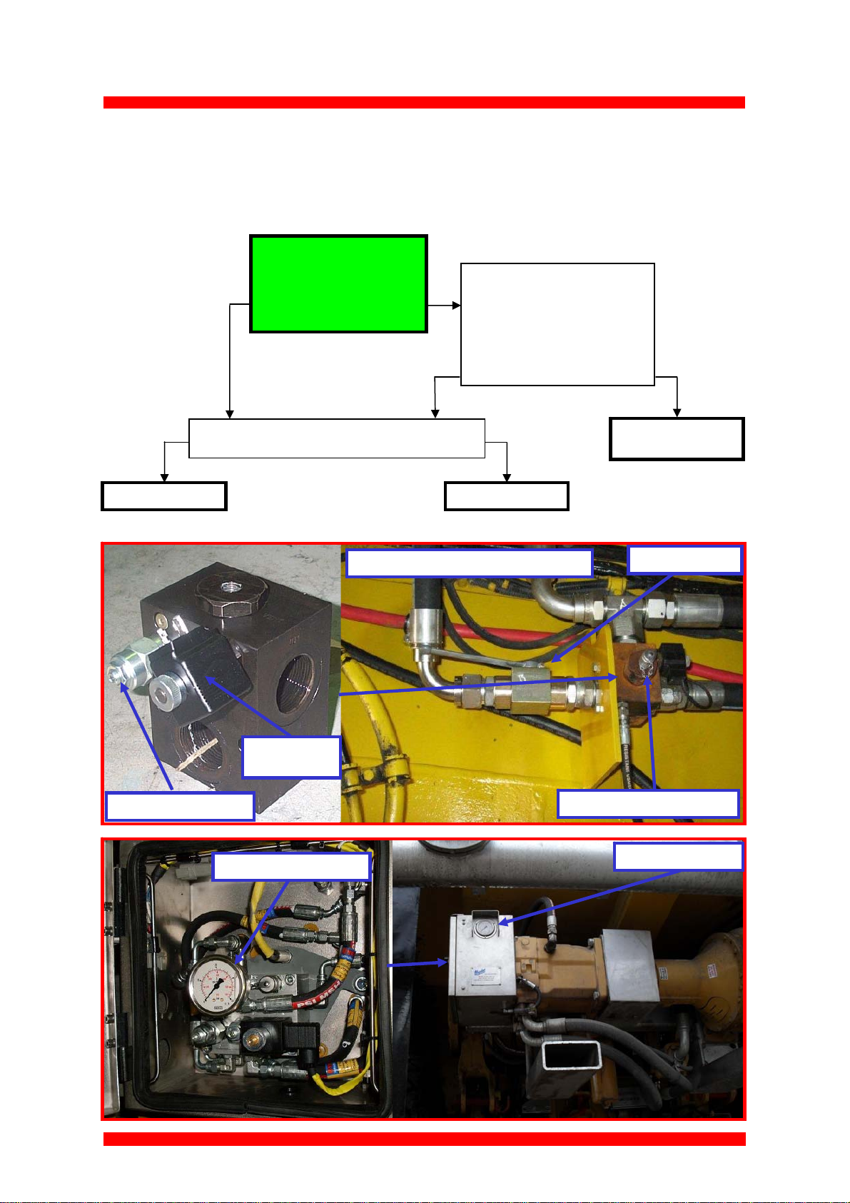
1.3 Foam system
1.3.1 System Diagnostics
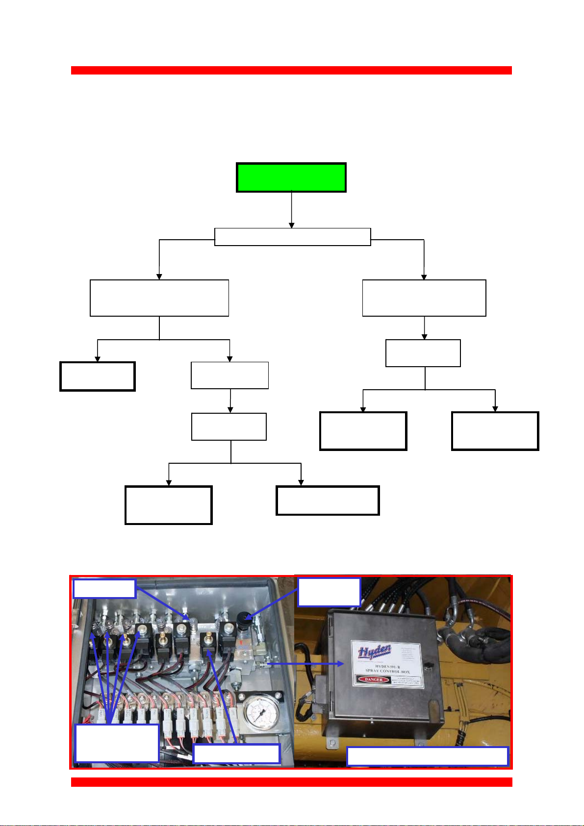
Foam system not working
Yes No
Yes No
There is a fault with the
foam pump module.
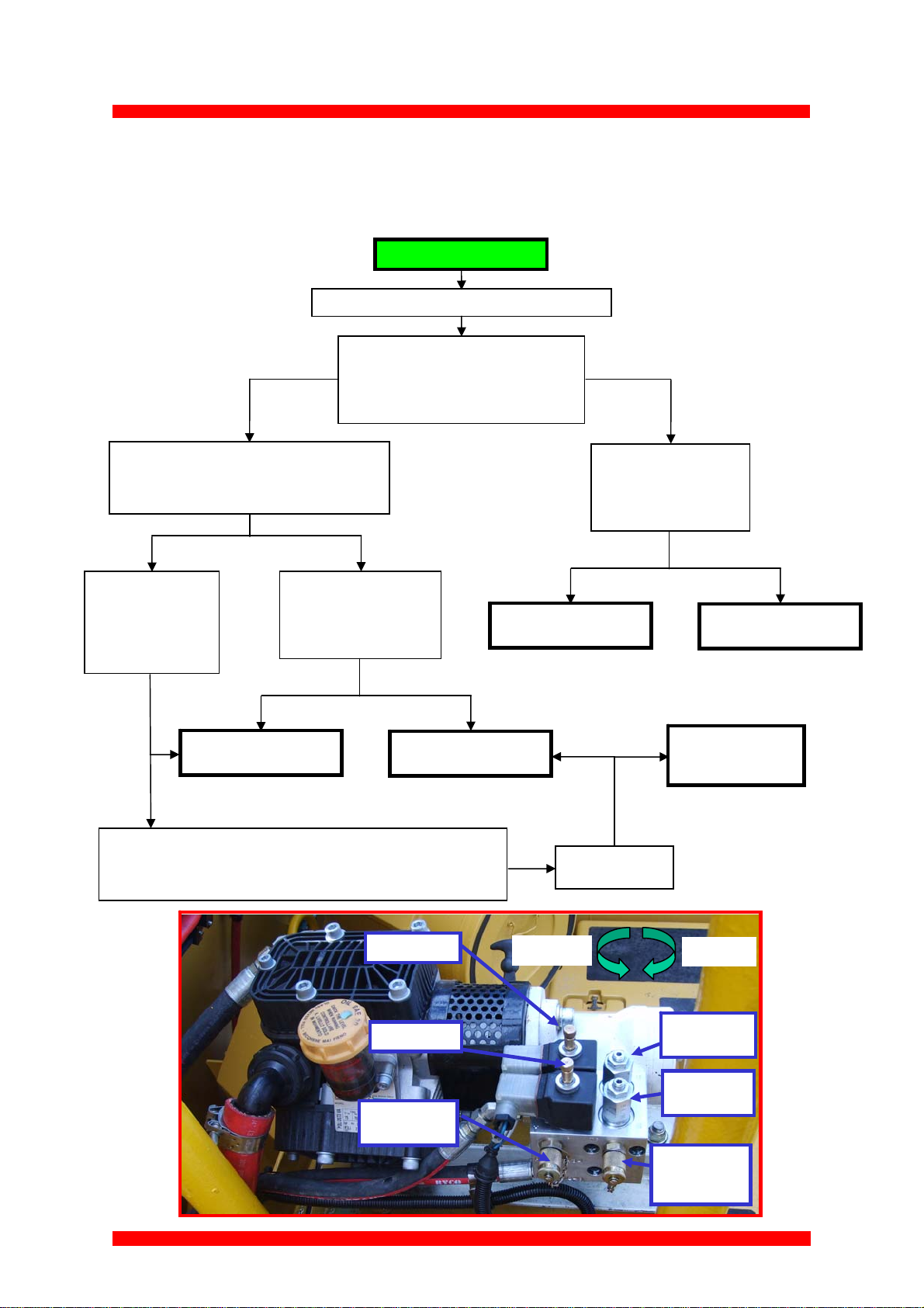
Did this fix the
problem?
Yes No
Congratulations you
have fixed the
problem.
Ensure the foam inlet ball valve is completely open.
Increase the Vari-rate to 40%.
Does the MID foam LED illuminate and the drive
shaft continue to rotate?
Engage the LOW foam
manual override.
Does the foam system start
to work?
While using the remote cannon set the Vari-
rate to low and start the foam system.
Does the Low foam LED illuminate and the
drive shaft start to rotate?
Increase the Vari-rate
further to 80%.
Do both the Low and
Mid LED plug
illuminate ?
There is an electrical fault.
See electrical diagnostics
Engage the MID foam
manual override.
Does the foam system start
to work ?
There is a fault with the
foam pump module.
Yes No
There is an electrical fault.
See electrical diagnostics
No
Setup a REV counter on the drive shaft.
Vari-rate @ low = 160-rpm Adjust Low flow control as required
Vari-rate @ 40% = 340-rpm Adjust Mid flow control as required
No Yes
Inlet pressure
test point
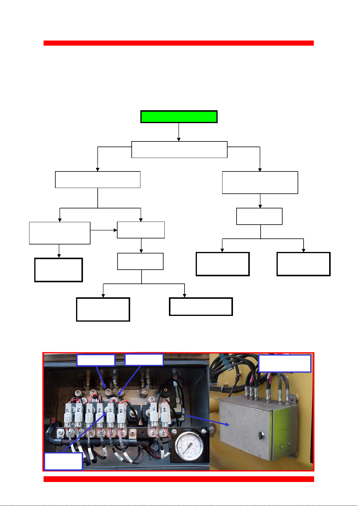
LOW foam
MID foam
MID foam
flow control
LOW foam
flow control
Increase
Decrease
Motor drive
pressure test
point