HydraMaster PEX 500 635K Operating instructions

HydraMaster
11015 47th Avenue West
Mukilteo, Washington 98275
56044659 Rev. B, Jan 2021
IMPROPER USE OF THE MACHINE WILL VOID THE WARRANTY
EL USO INCORRECTO DE LA MÁQUINA ANULARÁ LA GARANTÍA
UNE UTILISATION INCORRECTE DE LA MACHINE ANNULERA LA GARANTIE
No part of this manual may be reproduced or used in any form or by any means (i.e. graphic, electronic, photocopying or electronic
retrieval systems) without the express written permission of HydraMaster. Specications and information in this document are
subject to change without prior notice.
All rights reserved. © 2021 HydraMaster
INFORMATION AND OPERATING INSTRUCTIONS
INFORMACIÓN E INSTRUCCIONES DE USO
INFORMATION ET DIRECTIVES D’UTILISATION
PEX 500-Item #635K
Owner’s Manual
MODEL: 56113150
A-English
B-Español
C-Français
CAUTION: DO NOT OPERATE MACHINE UNTIL YOU HAVE READ
ALL SECTIONS OF THIS INSTRUCTION MANUAL
PRECAUCIÓN: NO UTILICE LA MÁQUINA HASTA HABER LEÍDO
TODAS LAS SECCIONES DE ESTE MANUAL DE INSTRUCCIONES
ATTENTION : N’UTILISEZ PAS LA MACHINE AVANT D’AVOIR LU
TOUTES LES SECTIONS DU PRÉSENT MANUEL

RX-20 / CMX-20 Owner’s Manual - 2PEX 500 - SP Owner’s Manual - 2
This page intentionally left blank.

3 - RX-20 / CMX-20 Owner’s Manual3 - PEX 500 - SP Owner’s Manual
Table of Contents
Introduction .................................................................................................................5
Parts and Service........................................................................................................5
Modications ...............................................................................................................5
Nameplate...................................................................................................................5
Uncrating the Machine ................................................................................................5
Cautions and Warnings...............................................................................................5
Grounding Instructions................................................................................................7
Know Your Machine ....................................................................................................9
Know Your Switch Plate ............................................................................................11
Preparing the Machine for Use .................................................................................12
Operating the Machine..............................................................................................12
After Using the Machine............................................................................................15
Maintenance Schedule..............................................................................................15
Power Cord Maintenance..........................................................................................15
Troubleshooting ........................................................................................................16
Technical Specications............................................................................................16
Water Flow Diagram .................................................................................................18
Electrical Diagram.....................................................................................................19
Wiringl Diagram Parts list .........................................................................................19
Assembly and Parts List............................................................................................21
2 Year Limited Warranty............................................................................................44
Warranty Registration ...............................................................................................45

RX-20 / CMX-20 Owner’s Manual - 4PEX 500 - SP Owner’s Manual - 4
This page intentionally left blank.

5 - RX-20 / CMX-20 Owner’s Manual5 - PEX 500 - SP Owner’s Manual
INTRODUCTION
This manual will help you get the most from your Carpet Extractor. Read it thoroughly before operating the machine.
This product is intended for commercial use only.
PARTS AND SERVICE
Repairs, when required, should be performed by an authorized HydraMaster distributor, who employs factory trained service
personnel, and maintains an inventory of original replacement parts and accessories.
Please contact the SERVPRO RMA/warranty to initiate service and locate an authorized service center near you.
MODIFICATIONS
Modications and additions to the cleaning machine which affect capacity and safe operation shall not be performed by the
customer or user without prior written approval from HydraMaster LLC. Unapproved modications will void the machine warranty
and make the customer liable for any resulting accidents.
NAMEPLATE
The Model Number and Serial Number of your machine are shown on the Nameplate, located on the rear base of the machine.
This information is needed when ordering repair parts for the machine. Use the space below to note the Model Number and
Serial Number of your machine for future reference. Be sure to register your warranty.
MODEL ________________________________________________
SERIAL NUMBER________________________________________
UNCRATING THE MACHINE
When the machine is delivered, carefully inspect the shipping carton and the machine for damage. If damage is evident, save
the shipping carton so that it can be inspected. Please contact the SERVPRO RMA/warranty to initiate service and locate an
authorized service center near you.
WARNING!
The Products sold with this Manual contain or may contain chemicals that are known to certain governments (such
as the State of California, as identied in its Proposition 65 Regulatory Warning Law) to cause cancer, birth defects
or other reproductive harm. In certain locations (including the State of California) purchasers of these Products
that place them in service at an employment job site or a publicly accessible space are required by regulation to
make certain notices, warnings or disclosures regarding the chemicals that are or may be contained in the Products
at or about such work sites. It is the purchaser’s responsibility to know the content of, and to comply with, any
laws and regulations relating to the use of these Products in such environments. The Manufacturer disclaims any
responsibility to advise purchasers of any specic requirements that may be applicable to the use of the Products in
such environments.

RX-20 / CMX-20 Owner’s Manual - 6PEX 500 - SP Owner’s Manual - 6
IMPORTANT SAFETY INSTRUCTIONS
This machine is only suitable for commercial use, for example in hotels, schools, hospitals, factories, shops
and ofces other than normal residential housekeeping purposes.
When using any electrical appliance, basic precautions should always be followed, including the following:
NOTE: Read all instructions before using this machine.
WARNING!
To reduce the risk of re, electric shock, or injury:
• This machine is not intended for use by persons (including children) with reduced physical, sensory or
mental capabilities, or lack of experience and knowledge.
•Do not leave the machine unattended when it is plugged in. Unplug the unit from the outlet when; not in use,
before cleaning the machine, prior to servicing or performing any maintenance on the machine, and when
replacing parts or converting the machine to another function.
•To avoid electric shock, do not expose to rain or snow. Store and use machine indoors only, store in a heated
location. Do not let the machine or wand freeze.
•Do not allow to be used as a toy. Close attention is necessary when used near children.
• High pressure cleaners shall not be used by children or untrained personnel.
•Use only as described in this manual. Use only the manufacturer’s recommended attachments.
•Never add water over 130º F/54º C to the solution tank.
• Always use a defoamer when foaming occurs to prevent vacuum motor damage (SERVPRO Defoamer item
#151).
• Do not let the pump run dry.
•Do not use with damaged cord or plug. If the machine is not working as it should, has been dropped, damaged,
left outdoors or dropped into water, please contact the SERVPRO RMA/warranty to initiate service and locate an
authorized service center near you.
•Turn off all controls before unplugging.
•Do not pull by the cord, use the cord as a handle, close a door on the cord, or pull the cord around sharp edges
or corners. Do not run the machine over the cord. Keep the cord away from heated surfaces. To unplug, grasp
the plug, not the cord.
•Do not handle the plug, the cord or the machine with wet hands.
•Extension cords must be 12/3 and no longer than 50 feet. Replace the cord or unplug immediately if the
ground prong becomes damaged.
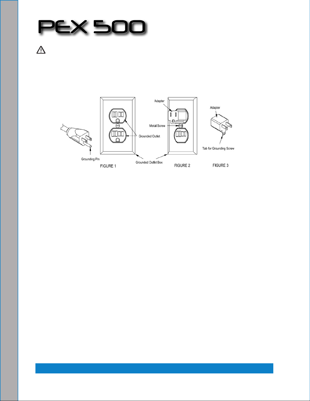
•Connect to a properly grounded outlet only.
•Do not put any object into openings. Do not use with any opening blocked; keep free of dust, lint, hair, and
anything that may reduce air ow.
• Keep loose clothing, hair, ngers, and all parts of body away from openings and moving parts.
•Do not pick up anything that is burning or smoking, such as cigarettes, matches, or hot ashes, or any health
endangering dusts. Do not use to pick up ammable or combustible liquids such as gasoline or use in areas
where they may be present.
• Risk of explosion – Do not spray ammable liquids.
•Use extra care when cleaning on stairs.
• Wear gloves or use rags when removing quick disconnects to prevent burns.
•Liquid ejected at the spray nozzle could be dangerous as a result of its temperature, pressure, or chemical
content.

7 - RX-20 / CMX-20 Owner’s Manual7 - PEX 500 - SP Owner’s Manual
• High pressure jets can be dangerous if subject to misuse. The jet must not be directed at persons, live electrical
equipment or the machine itself.
• Do not use the machine within range of persons unless they wear protective clothing.
• Do not direct the jet against yourself or others in order to clean clothes or foot-wear.
• High pressure hoses, ttings and couplings are important for the safety of the machine. Use only hoses, ttings
and couplings recommended by the manufacturer.
• To ensure machine safety, use only original spare parts from the manufacturer or approved by the manufacturer.
• Water that has own through backow preventers is considered to be non-potable.
• Do not use the machine if a supply cord or important parts of the machine are damaged, e.g. safety devices,
high pressure hoses, trigger gun.
120VAC GROUNDING INSTRUCTIONS
This appliance must be grounded. If it should electrically malfunction, grounding provides a path of least resistance for electric
current to reduce the risk of electric shock. This appliance is equipped with a cord having an equipment-grounding conductor and
grounding plug. The plug must be plugged into an appropriate outlet that is properly installed and grounded in accordance with
all local codes and ordinances.
DANGER!
Improper connection of the equipment-grounding conductor can result in a risk of electric shock. Check with
a qualied electrician or service person if you are in doubt as to whether the outlet is properly grounded. Do
not modify the plug provided with the appliance. If it will not t the outlet, have a proper outlet installed by a
qualied electrician.
This appliance is for use on a nominal 120-volt circuit, and has a grounding plug that looks like the plug illustrated in Figure 1
below. A temporary adapter illustrated in Figures 2 and 3 may be used to connect this plug to a 2-pole receptacle as shown in
Figure 2 if a properly grounded outlet is not available. The temporary adapter should be used only until a properly grounded
outlet (Figure 1) can be installed by a qualied electrician. The green-colored rigid ear, tab, or the like extending from the adapter
must be connected to a permanent ground such as a properly grounded outlet box cover. Whenever the adapter is used, it must
be held in place by a metal screw. Grounding adapters are not approved for use in Canada.
Replace the plug if the grounding pin is damaged or broken.
The Green (or Green/Yellow) wire in the cord is the grounding wire. When replacing a plug, this wire must be attached to the
grounding pin only.
Extension cords connected to this machine should be 12 gauge, three-wire cords with three-prong plugs and outlets. DO NOT
use extension cords more than 50 feet (15 m) long.

RX-20 / CMX-20 Owner’s Manual - 8PEX 500 - SP Owner’s Manual - 8
WARNING!
• If an extension cord is used, the plug and socket must be of watertight construction.
• Inadequate extension cords can be dangerous.
• Extension cords must be 12/3 and no longer than 50 feet. Replace the cord or unplug immediately if the
ground prong becomes damaged.
PLEASE NOTE: FOR NORTH AMERICA ONLY
Grounding adapters are not approved for use in Canada.

9 - RX-20 / CMX-20 Owner’s Manual9 - PEX 500 - SP Owner’s Manual
KNOW YOUR MACHINE
1 Solution Hose Quick Disconnect
2 Solution Tank Fill Opening
3 Vacuum Hose Barb
4 Drain Hose
5 Handles
6 Roller Balls
7 Wheel
8 Castor
9 Solution Filter
10 Recovery Tank Shutoff Float

RX-20 / CMX-20 Owner’s Manual - 10PEX 500 - SP Owner’s Manual - 10
KNOW YOUR MACHINE (CONTINUED)
11 Recovery Tank Lid
12 Switch Plate
13 Wand Storage Clip
14 Pressure Adjustment Knob
15 Pressure Gauge
16 Pressure Relief Valve
17 Cord Retainer Straps (four)
18 Hour Meter (Optional)
19 Wand Retainer Bracket
20 Power Cords
21 Hose Hangers (two)

11 - RX-20 / CMX-20 Owner’s Manual11 - PEX 500 - SP Owner’s Manual
ABCDE
KNOW YOUR SWITCH PLATE
A Solution Pump Switch - This switch turns the solution pump ON and OFF.
B Vacuum Switch - This switch turns the rst of the two vacuum motors ON and OFF.
C Vacuum Switch - This switch turns the second of the two vacuum motors ON and OFF.
D Circuit Indicator - When this light is on, it indicates that the two cords are on a separate circuit.
CAUTION!
The circuit breaker in the wall panel can trip if both cords are on the same circuit.
E Heat Switch - This three position switch controls the water temperature. Position (I) is low temperature, Position (O) is OFF
and Position (II) is high temperature.

RX-20 / CMX-20 Owner’s Manual - 12PEX 500 - SP Owner’s Manual - 12
PREPARING THE MACHINE FOR USE
See the diagrams in the “Know Your Machine” section.
1Inspect the machine, hoses, and cleaning tools for cleanliness and completeness.
2 Screw the Recovery Tank Lid (11) closed. Ensure the drain cap is closed tightly.
3 Pre-spray spots and heavy trafc areas before extracting with the detergent of your choice. Mix the pre-spray according to
the detergent manufacturer’s directions.
4 Fill the solution tank with clear water (12 gal. / 45.5 L capacity). If desired, add a detergent or rinse of your choice (we
recommend a CRI approved detergent). If you choose to add a detergent to the solution tank, be sure to mix well, and
always follow the use & dilution instructions on the detergent label. Only use a detergent with a pH between 5 and
10. Although this machine is designed to supply instant hot water, the addition of warm water to the solution tank would
increase heater efciency. Never use water above 130º F/54º C in the solution tank.
CAUTION!
Use low-sudsing, liquid detergents designed for carpet extraction.
OPERATING THE MACHINE
See the diagrams on page A-14.
1 Follow the instructions in the Preparing the Machine for Use section of this manual.
2Turn off all the switches. Plug the power cords into properly grounded outlets. Do not connect both cords to the same
outlet; the green, Circuit Indicator Light (D) on the switch plate should light up. If the indicator light does not come on, try
different outlets until it does. “Do not connect both cords to the same outlet.”
3Attach the priming hose to the machine and place the open end into the solution tank.
4Turn ON the solution pump (A) and let it run until the pump is fully primed (approximately 30 seconds to 1 minute). Once
the pump is primed, turn off the pump and remove the priming hose.
5 Connect a solution line to the Solution Hose Quick Disconnect (1). Attach the other end of the solution line to the cleaning
tool.
NOTE: If there is pressure built up in the solution lines, it may be difcult to connect a solution line to the Quick
Disconnect (1). If this is the case place the Pump Switch (A) into the OFF (O) position. Momentarily turn the Pressure Relief
Valve (16) from the green “checkmark” position to the red “X” position and back again to the green “checkmark” position, this will
relieve the pressure to allow a solution line to be connected to the quick disconnect port.
CAUTION!
Always operate the machine with the Pressure Relief Valve set to the Green “checkmark” position to avoid
possible damage.
6Connect a vacuum hose to the Vacuum Hose Barb (3). Attach the other end of the vacuum hose to the cleaning tool.
7To use heated water for cleaning, press the Heat Switch (E) into either the Low Temperature position (I) or the High
Temperature position (II). Wait two minutes for the heat exchanger to reach temperature.
8 Press the Pump Switch (A) to ON (I).
9 Press the Vacuum Switches (B &C) to ON (I). The machine can be used with only one vacuum motor running for less
suction i.e. cleaning upholstery.
10 Spray through your tool a few times to ll the lines with solution. Begin cleaning.
11 To adjust the solution spray pressure; rotate the Pressure Adjustment Knob (14) clockwise to increase pressure and
counterclockwise to decrease pressure. The pump spraying pressure will be observable at the Pressure Gauge (15) while
spraying. Make sure the cleaning tool is spraying when adjusting the pressure, otherwise the pressure reading will be
inaccurate.
12 Watch the uid entering the Recovery Tank Lid (11). If there is a large amount of suds in the recovery tank, add a
defoamer chemical (SERVPRO Defoamer item #151) to the recovery tank.
CAUTION!
• Empty the recovery tank before the uid or foam enters the vacuum motor.
• If foam or liquid escapes from the machine, switch off immediately.

13 - RX-20 / CMX-20 Owner’s Manual13 - PEX 500 - SP Owner’s Manual
CAUTION!
Always make sure the oat is clean and travels freely before turning on the machine. A oat that is stuck
will cause the vacuum motor to suck in water, resulting in vac motor damage.
13 The recovery tank has a Recovery Tank Shutoff Float (10) to block the vacuum system when the recovery tank is full.
You can tell when the oat closes by the sudden change in the sound of the vacuum motor. When the oat closes, the recovery
tank must be emptied. The machine can continue to dispense solution, but will not pick up water with the oat closed.
14 Monitor the water level in the solution tank. Do not let the pump run dry. When the solution tank gets low, turn off the
pump and the vacuum motor(s), rell the solution tank with water and the proper ratio of cleaning detergent. Empty the recovery
tank and continue cleaning.
15 When the operator has completed the job; vacuum all unused solution from the solution tank into the recovery tank,
turn off the pump, vacuum motor(s) and heat exchanger. Unplug the machine.
16 Push the machine to a designated waste water “DISPOSAL SITE” and empty the recovery tank. To empty, loosen the
Velcro strap retaining the Recovery Tank Drain Hose (4) into its side storage location, then remove the plug (hold the end of the
hose above the water level in the tank to avoid sudden, uncontrolled ow of waste water).
17 Follow the instructions in the After Using the Machine section of this manual.

RX-20 / CMX-20 Owner’s Manual - 14PEX 500 - SP Owner’s Manual - 14
OPERATING THE MACHINE

15 - RX-20 / CMX-20 Owner’s Manual15 - PEX 500 - SP Owner’s Manual
AFTER USING THE MACHINE
See the diagrams on pages A-9, A-10 and A-14.
1To empty the solution tank, open Solution Tank Fill Opening (2) and vacuum out all unused solution into the recovery
tank using the vacuum hose. Rinse the tank with clean water.
2Turn all the Power Switches (A, B, C & E) to OFF (O). Unplug the Power Cords (20). Coil the cords and secure them
to the rear of the machine using the four Cord Retainer Straps (17).
3To empty the recovery tank, loosen the Velcro strap retaining the Recovery Tank Drain Hose (4) into its side storage
location. Direct the hose to a designated waste water “DISPOSAL SITE” and remove the plug (hold the end of the hose above
the water level in the tank to avoid sudden, uncontrolled ow of waste water). Rinse the tank with clean water. Inspect the drain
hose; replace if kinked or damaged.
4Disconnect the solution and vacuum hoses from the machine, at the Solution Hose Quick Disconnect (1) and Vacuum
Hose Barb (3) respectively. Flush the vacuum hose with warm water to wash any debris out of the vacuum hose and cleaning
tool. Inspect them for damage. Fold down the Hose Hangers (21) and the hoses can be wrapped around the machine for
storage. Set the wand on the Wand Retainer Bracket (19) and secure to the back of the machine at the Wand Storage Clip (13).
NOTE: Trigger wand when disconnecting solution line to release pressure.
5Wipe the machine with a damp cloth. Do not use abrasive chemicals or solvents.
6Perform any required maintenance before storage.
MAINTENANCE SCHEDULE
MAINTENANCE ITEM Daily Weekly Yearly
Check / Clean Tanks & Hoses •
Check / Clean Recovery Tank Shut-Off Float •
Clean Extraction Wand/Tool •
Inspect & Clean Solution Filter •
*Check Carbon Brushes •
* Have a Hydramaster service technician check the vacuum motor carbon brushes once a year or after 300 operating hours.
Check the pump motor carbon brushes every 500 hours or once a year.
IMPORTANT!
Motor damage resulting from failure to service the carbon brushes is not covered under warranty.
See the Limited Warranty Statement.
7Store the machine indoors in a clean, dry place with the recovery tank lid open. Keep from freezing.
POWER CORD MAINTENANCE
Once a week (or more often if necessary), check the power cords for cracked or damaged insulation, exposed wires in the cord
or plug, and damaged or missing ground pin. Repair or replace damaged cord or plug immediately.

RX-20 / CMX-20 Owner’s Manual - 16PEX 500 - SP Owner’s Manual - 16
TROUBLESHOOTING:
IF THIS
OCCURS CHECK THIS
NO SPRAY
Solution tank is empty, or lter is plugged.
Clogged spray tip(s).
Pump not running or not primed.
Valve on wand not operating.
Solution hose not completely connected to machine.
Contact your distributor for additional help.
LOW PUMP
PRESSURE
Check to see that the pressure relief valve is fully seated in the green checkmark “operating” position.
Contact your distributor for additional help.
PUMP DOES
NOT RUN
Pump switch is not turned on.
No power in the wall outlet - check to see if the breaker has tripped.
Contact your distributor for additional help.
LOW SUCTION
Debris is plugging cleaning tool or vacuum hose.
Drain hose cap is not completely closed.
Recovery tank lid is not seated, or gasket is damaged.
Contact your distributor for additional help.
NO SUCTION
Recovery tank is full and needs to be emptied.
Recovery tank ball oat is stuck closed. Clean so ball moves freely.
No power in the wall outlet - check to see if the breaker has tripped.
Contact your distributor for additional help.
LOW HEAT
Spraying too much water:
• Spraying too long. Try spraying for 12-15 seconds, or about three strokes.
• Spray tips(s) too large. Use a maximum of two HydraMaster part number 000-076-122 spray tip(s).
Longer hose or larger diameter hose than recommended. Use a maximum of 25-foot-long ¼ inch hose
for best results.
Heat exchanger needs to be ushed.
Contact your distributor for additional help.
NO HEAT
Heat is not turned on.
No power in the wall outlet - check to see if the breaker has tripped.
Call your distributor for additional help.
TECHNICAL SPECIFICATIONS (as installed and tested on the unit)
Model 635K
Model No. 56113150 (PEX 500H-SP)
Voltage/frequency 120 V / 60 Hz
Rated Current 15 Amp
Protection Class (electrical) Class 1
Sound Pressure Level (IEC 60704-2-1) 68.7 dB LpA, 3 dB KpA
Total Weight 110 lbs. (49.8 kg)
Solution Tank Capacity 12 gal (45.5 L)
Recovery Tank Capacity 10 gal (37.8 L)

17 - RX-20 / CMX-20 Owner’s Manual17 - PEX 500 - SP Owner’s Manual

PEX 500 - SP Owner’s Manual - 18
PEX 500 Owner’s Manual - 18
PEX 500 - Water Flow Diagram
26 PEX 500-C-TICK - 56042658 7/2016
PARTS LIST
8
7
5
4
6
3
1
2
* = Optional, Not Included
WATER FLOW DIAGRAM
BLUE = FRESH WATER
GREEN = 500PSI WATER FLOW
PURPLE = PRESSURE RELIEF RETURN TO TANK
RED = 500PSI HEATED WATER FLOW
Item Description
1 Solution Tank
2 Fresh Water Inlet Filter
3 500PSI Pump
4 Unloader Valve
5 Pressure Gauge
6 Pressure Relief Valve
7 500PSI Quick Connect
8 Heater
BLUE = FRESH WATER
GREEN = 500 PSI WATER FLOW
PURPLE = PRESSURE RELIEF RETURN TO TANK
RED = 500 PSI HEATED WATER FLOW
ITEM DESCRIPTION
1Solution Tank
2Fresh Water Inlet Filter
3500PSI Pump
4Unloader Valve
5Pressure Gauge
6Pressure Relief Valve
7500PSI Quick Connect
8Heater
Water Flow Diagram

19 - PEX 500 - SP Owner’s Manual
HydraMaster PEX 500 F
19 - PEX 500 Owner’s Manual
Electrical Diagrams
PEX 500 - Wiring Diagram
O
RMS.DSN - E SIZE FORM 4/24/96
NOTES:
1. REF DRAWING 56113045 DIAGRAM-WIRING
PLYMOUTH, MINNESOTA AND IT HAS BEEN ISSUED WITH THE UNDERSTANDING THAT IT WILL NOT BE REPRO-
DWG. NO.
THIS DRAWING AND THE DESIGN REPRESENTED HEREON IS THE PROPERTY OF NILFISK-ADVANCE, INC.,
DUCED NOR COPIED NOR USED FOR ANY PURPOSE OTHER THAN FOR WHICH IT WAS ISSUED AND RECIPIENT
REV
SHEET
APPDECO DATE
A
CONFIDENTIAL
DFTM
AGREES TO RETURN IT UPON REQUEST.
REVISIONS
B
BUT BEFORE PAINTING.
ASSY.
E
NONE
1. ALL DIMENSIONS IN INCHES.
APPROVED
APPROVED
DRAWN
NILFISK-ADVANCE, INC.
SIZE
AS NOTED.
CODE
APPROVED
UNITS IN [ ] ARE ISO METRIC
REV.
NOTES UNLESS OTHERWISE
SPECIFIED
4. REMOVE ALL BURRS AND SHARP
CHECKED
EDGES.
FIRST USED ON
ORCAD
PROJ ENG
DIM. IN [ ] ARE MM.
DWG. NO.
2. DO NOT SCALE DRAWING.
TITLE
SHEET
3. ALL DIMENSIONS APPLY AFTER
PLYMOUTH, MINNESOTA 55447-3408
SCALE
PLATING AND HEAT TREATING,
56113044 1 OF 1
1 OF 1
DIAGRAM-LADDER
56113044
PMO
PEX
5-13-10 PMO WGL
RELEASE
WGL
5-13-10
L1 L2
L1 L2
5-13-10
MAIN POWER 2
MAIN POWER 1
MAIN POWER 1
ALTERNATE CIRCUIT FOR PUMP M1
L1 L2
56113E01
120V MACHINE ONLY
A-06220
B
A-06413 2-18-11 PMO WGL
UPDATE: S1 WAS S5, H1 WAS E2, ADD:
ALTERNATE CIRCUIT FOR PEX 500-CTICK
B
B
L1 L2
MAIN POWER 1
FERRITE
ALTERNATE CIRCUIT FOR PEX 500-CTICK
B
WHT
VIO
BLK
RED/WHT
BLK/WHT
GRN/YEL
WHT
BLK
RED
RED
YEL/WHT
BLK
WHT
BLK ORN
RED/WHT
WHT
BLK BLU
BRN/WHT
GRN/YEL
GRN/YEL
GRN/YEL
BLK
BLK
WHT
BLK
RED
YEL/WHT BLK
GRN/YEL
GRN/YEL
RED
YEL/WHT
WHT
RED
YEL/WHT
YEL/WHT
WHT
BLK
RED
RED
YEL/WHT
WHT
BLK ORN
RED/WHT
WHT
BLK BLU
BRN/WHT
GRN/YEL
GRN/YEL
GRN/YEL
RED
BLK
H1
240V LAMP NEON
H1
240V LAMP NEON
S1S1
1
2
3
4
SW5
TEMP 1
SW5
TEMP 1
M
M2
VAC 1
M
M2
VAC 1
1 2
L5
CHOKE COIL
L5
CHOKE COIL
M
M1
PUMP 500 PSI
M
M1
PUMP 500 PSI
-+
~
E6
FILTER
~
E6
FILTER
E2
HOURMETER (OPTION)
E2
HOURMETER (OPTION)
1
2
~
~
+-
E1
BRIDGE
~
~
+-
E1
BRIDGE
HEAT ELEMENTHEAT ELEMENT
1 2
L1
CHOKE COIL
L1
CHOKE COIL
L4
CHOKE COIL
L4
CHOKE COIL
S4
HEATER
S4
HEATER
1
2
3
4
5
6
M
M1
PUMP 200 PSI
M
M1
PUMP 200 PSI
-+
E2
HOURMETER (OPTION)
E2
HOURMETER (OPTION)
1
2
S1S1
1
2
3
4
S3S3
1
2
3
4
M
M3
VAC 2
M
M3
VAC 2
1 2
E2
HOURMETER(OPTION)
E2
HOURMETER(OPTION)
1
2
S2S2
1
2
3
4
S1S1
1
2
3
4
M
M2
VAC 1
M
M2
VAC 1
1 2
L3
CHOKE COIL
L3
CHOKE COIL
M
M1
PUMP 500 PSI
M
M1
PUMP 500 PSI
-+
L6
CHOKE COIL
L6
CHOKE COIL
SI3
TEMP CUT-OFF
SI3
TEMP CUT-OFF
S3S3
1
2
3
4
S2S2
1
2
3
4
~
E5
FILTER
~
E5
FILTER
SW6
TEMP 2
SW6
TEMP 2
M
M3
VAC 2
M
M3
VAC 2
1 2
L2
CHOKE COIL
L2
CHOKE COIL
~
~
+-
E1
BRIDGE
~
~
+-
E1
BRIDGE
Item Ref. No. Qty. Description
E1 1579 1 Rectier, 15 Amp
E2 56113108 1 Kit-Hour Meter (Optional)
H1 227 1 Light Green
M1 56113101 1 Kit-Pump Motor 120V
M2 56113144 2 Vac Motor-120V-3 Stage
* 56113056 1 Vac Motor Brush Kit-120V
M3 56113144 2 Vac Motor 120V-3 Stage
* 56113056 1 Vac Motor Brush Kit-120V
S1 1644 1 Switch, Pump
S2 1644 1 Switch, Vac
S3 1644 1 Switch, Vac
S4 56113029 1 Switch, Heater
SW5 399 1 Thermostat
SW6 56113030 1 Thermostat
S13 81 1 Thermal Cutout
Wiring Diagram Parts List

Assemblies and Parts Lists: 20 HydraMaster PEX 500
PEX 500 Owner’s Manual - 20
This manual suits for next models
1
Table of contents
Other HydraMaster Floor Machine manuals
Popular Floor Machine manuals by other brands

Kompernass
Kompernass KH 750 operating instructions

Windsor
Windsor VOYDU 10086130 operating instructions

Minuteman
Minuteman Lumina 20 M26036QP Operation service parts care

Numatic
Numatic LoLine NLL 332 Owner's instructions

Numatic
Numatic TTB-1620/100 owner's manual

Kärcher
Kärcher BR 35/12 C BP quick start guide