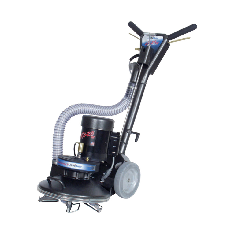
HydraMaster RX20 NEXTGEN 120 VAC User manual

RX20 Rotary Extractor
Owner’s Manual
700-041-030 700-041-332
700-041-031 700-041-333
700-041-330
700-041-331
700-041-334
700-041-407
HydraMaster
11015 47th Avenue West
Mukilteo, Washington 98275
MAN-47328 Rev.A, April 2018
(P/N 000-182-171D)
No part of this manual may be reproduced or used in any form or by any means (i.e. graphic, electronic, photocopying or electronic
retrieval systems) without the express written permission of HydraMaster. Specications and information in this document are
subject to change without prior notice.
All rights reserved. © 2018 HydraMaster
DOMESTIC AND INTERNATIONAL

This page intentionally left blank.

i - RX-20 / CMX-20 Owner’s Manuali - RX-20 Owner’s Manual
Table of Contents
INTRODUCTION.......................................................................................... SECTION 1
Contact Information................................................................................. 1-2
Warnings, Cautions and Notices............................................................. 1-3
MACHINE SPECIFICATIONS ...................................................................... SECTION 2
Congurations......................................................................................... 2-2
ASSEMBLY INSTRUCTIONS ...................................................................... SECTION 3
OPERATING INSTRUCTIONS..................................................................... SECTION 4
Preparation.............................................................................................. 4-1
Operation ................................................................................................ 4-2
Maneuvering the RX20 ........................................................................... 4-2
Edging Tool ............................................................................................. 4-3
CLEANING INFORMATION ......................................................................... SECTION 5
Cleaning Patterns.................................................................................... 5-1
Special Information ................................................................................. 5-2
Cleaning Hints......................................................................................... 5-2
MACHINE MAINTENANCE.......................................................................... SECTION 6
Daily Maintenance................................................................................... 6-1
Periodic Maintenance.............................................................................. 6-4
Transport and/or Storage ........................................................................ 6-5
Freeze Warning and Protection .............................................................. 6-5
ELECTRICAL DIAGRAMS ........................................................................... SECTION 7
ASSEMBLY DRAWINGS AND PARTS LISTS.............................................. SECTION 8
REPAIR AND REPLACEMENT .................................................................... SECTION 9
Felt Vacuum Seal ................................................................................... 9-1
High Pressure Valve Assembly .............................................................. 9-2
Locking Mechanism (Bushing Replacement) ......................................... 9-3
TROUBLESHOOTING ................................................................................. SECTION 10
WARRANTY INFORMATION ....................................................................... SECTION 11
HydraMaster Limited Warranty ............................................................... 11-1

RX-20 / CMX-20 Owner’s Manual - iiRX-20 Owner’s Manual - ii
List of Figures
Figure 2-1. RX20 Optional Equipment.........................................................................2-3
Figure 3-1. Fully Assembled RX20..............................................................................3-1
Figure 4-1. Solution and Vacuum Hose Connections..................................................4-1
Figure 4-2. Powerhead Maneuvers Like a Buffer........................................................4-2
Figure 4-3. Incorrect Maneuver ...................................................................................4-3
Figure 4-4. Correct Cleaning Patterns.........................................................................4-4
Figure 5-1. Clean into Area or Room...........................................................................5-2
Figure 6-1. Remove Nut/Inline Filter............................................................................6-1
Figure 6-2. Check Jet Spray for Even Flow.................................................................6-2
Figure 6-3. Loosen Cleaning Head Assembly .............................................................6-2
Figure 6-4. Location of Rotary Union...........................................................................6-2
Figure 6-5. Clean Off Debris from Gear Box Shaft......................................................6-3
Figure 6-6. Lubricate Vacuum Seal on Top of Hub......................................................6-3
Figure 6-7. Lubricate Shaft and Re-install Head Assembly.........................................6-3
Figure 6-8. Remove Retaining Clip with Screwdriver..................................................6-4
Figure 6-9. Tighten Setscrew.......................................................................................6-4
Figure 7-1. Wiring Diagram - 120 VAC / 60 Hz............................................................7-1
Figure 7-2. Wiring Diagram - 230 VAC / 50 Hz............................................................7-2
Figure 8-1. RX20 Final Assembly................................................................................8-2
Figure 8-2. Base and Drive Train Assembly (120 VAC / 60 Hz) - View 1 of 2 .............8-4
Figure 8-3. Base and Drive Train Assembly (120 VAC / 60 Hz) - View 2 of 2 .............8-5
Figure 8-4. Upper and Lower Handle Assembly (120 VAC / 60 Hz) - View 1 of 3.......8-7
Figure 8-5. Upper and Lower Handle Assembly (120 VAC / 60 Hz) - View 2 of 3.......8-8
Figure 8-6. Upper and Lower Handle Assembly (120 VAC / 60 Hz) - View 3 of 3.......8-9
Figure 8-7. Vacuum Head Assembly ......................................................................... 8-11
Figure 8-8. Valve Stem Assembly..............................................................................8-13
Figure 8-9. Solution Valve Assembly .........................................................................8-14
Figure 8-10. Vacuum Shoe and Skid Assembly ........................................................8-15
Figure 8-11. Edging Tool No Relief Assembly ..........................................................8-16
Figure 8-12. Cartridge Filter Assembly .....................................................................8-17

iii - RX-20 / CMX-20 Owner’s Manualiii - RX-20 Owner’s Manual
Figure 9-1. Carefully Pry Seal Up and Lift Out ............................................................9-1
Figure 9-2. Use Can to Hold Oil for Seal.....................................................................9-2
Figure 9-3. Quick Connect, Back Plate and Stainless Steel Hose
Removed from Upper Handle Assembly...................................................9-3
Figure 9-4. Remove Cotter Pin and Remove Dog Point Set Screw ............................9-4
Figure 9-5. Reinstall Dog Point Set Screw ..................................................................9-5

RX-20 / CMX-20 Owner’s Manual - ivRX-20 Owner’s Manual - iv
This page intentionally left blank.

1-1: Owner’s Manual
1- Introduction
Congratulations,
You now own a piece of equipment that incorporates the latest in carpet, tile and grout
cleaning technology. Your foresight in purchasing an RX20 shows that you care enough
to give your customer the maximum cleaning process available. You have invested in
not only a cleaning tool, but a marketing
tool that will enhance your professional
image in every way.
The RX20’s features will almost certainly
increase your productivity while decreasing
the fatigue factor that may have prevented
you from going after some of the larger
cleaning jobs that are available to carpet
cleaners and maintenance professionals
today.
Your new RX20 is a powerful Rotary
Jet Extractor that has been precision
engineered to bring you to the state-of-the-art in carpet, tile and grout cleaning. The
RX20’s weight distribution and rotary motion enable the operator to maneuver the unit
easily with less fatigue and without back strain.
The RX20’s electric motor drives its precision transmission which, in turn, rotates the
head, or star, assembly. Cleaning solution is injected through the center of the gear box
shaft directly to the three spray jets.
Soiled solution is then extracted from the carpet by ve
stainless steel cleaning heads and drawn through the
aluminum exhaust manifold to your cleaning system’s
recovery tank.
The RX20 is available in either the 120VAC / 60
Hz version or the 230VAC / 60Hz & 230VAC /
50Hz versions. Photos and illustrations throughout
this manual show only the RX20 120VAC / 60 Hz
version due to space limitations.

Owner’s Manual: 1-2
CONTACT INFORMATION
If you have any questions regarding the operation, maintenance or repair of this machine,
refer to the following information and contact the appropriate HydraMaster department.
Hours Telephone Numbers E-mail Addresses
Monday-Friday (425) 775-7275 Support Tech Support:
techsupport@hydramaster.com
7:00 a.m. to 5:00
p.m. (425) 775-7276 Parts Parts Support:
parts@hydramaster.com
Pacic Time
FAX
(425) 771-7156 - Parts
(800) 426-4225 - Support
When calling your distributor, be sure to reference the serial number and date of purchase.
FOR YOUR REFERENCE:
Serial No.____________________________________________________
Date of Purchase:_____________________________________________
Purchased From (Distributor): __________________________________

1-3: Owner’s Manual
WARNINGS, CAUTIONS AND NOTICES
HydraMaster uses this WARNING symbol throughout the manual to warn of
possible injury or death.
This CAUTION symbol is used to warn of possible equipment damage.
This NOTICE symbol indicates that federal or state regulatory laws may apply,
and also emphasizes supplemental information.

Owner’s Manual: 1-4
This page intentionally left blank.

2-1: Owner’s Manual
2- Machine Specications
RX20 - 120 VAC RX20 - 230 VAC
Length 23” 23”
Base Width 21” 21”
Height - Standard Up to 43” Up to 43”
Weight 62 lbs 62 lbs
Motor 1/2 HP Totally Enclosed
Fan-Cooled
1/2 HP Totally Enclosed,
Fan-Cooled
Voltage 120VAC/60Hz 230VAC/50 Hz or 60 Hz
Gear Box
1,725 rpm Input
130 rpm Output
Permanently Lubricated
Helical Gear Drive
230V/50Hz 230V/60Hz
1,450 rpm
Input
109 rpm Output
Permanently
Lubricated
Helical Gear
Drive
1,725 rpm
Input
130 rpm Output
Permanently
Lubricated
Helical Gear
Drive
Oil Capacity 12 oz 12 oz
Star Head Plate Replaceable, Spring Steel
Arms
Replaceable, Spring Steel
Arms
Cleaning Heads Five Cast Aluminum Five Cast Aluminum
Solution Jets Three Stainless Steel
Conejet 1/8GG SS1
Three Stainless Steel
Conejet 1/8GG SS1
Solution Strainer Mesh, Stainless Mesh, Stainless
Solution Valve Stainless Steel,
High Pressure
Stainless Steel,
High Pressure
Cleaning Rate
Five Heads Rotating at
130 rpm = 650 Cleaning
Passes/Minute
230 VAC/50 Hz 230 VAC/60 Hz
Five Heads
Rotating at
109 rpm = 545
Cleaning
Passes/Minute
Five Heads
Rotating at
130 rpm = 650
Cleaning
Passes/Minute

Owner’s Manual: 2-2
RX20 - 120 VAC RX20 - 230 VAC
Handle Assembly Foam Grips Foam Grips
Transportation
Wheels
8” diameter, 1-1/2” Wide;
Gray, Non-Marking
8” diameter, 1-1/2” Wide;
Gray, Non-Marking
Electric Cord 50 ft, 14/3 50 ft w/M-F IEC Ends 230 V
The base, exhaust manifolds, handle, gear box housing and cleaning heads are all cast
aluminum. Other parts are either metal or high impact plastic.
The operating temperature and pressure of the cleaning solution as well as the
vacuum power depend entirely on the type of cleaning system you use.
CONFIGURATIONS
When selecting your high efciency rotary extractor machine, you have these models
from which to choose:
If you want this conguration: Order this P/N:
RX20 - 120VAC/60Hz 700-041-030
RX20 - 230VAC/60Hz 700-041-031
RX20 - 230VAC/50Hz 700-041-032
See detailed parts lists for all congurations.

2-3: Owner’s Manual
OPTIONAL EQUIPMENT
To better meet your business needs, HydraMaster offers these
options that you can add to your basic rotary extractor system:
If you want this
option:
Order this P/N:
Pad and Bonnet
Driver
190-041-020
(Top Photo,
Figure 2-1)
Hard Floor
Attachment (LD)
190-041-024
(Middle Photo,
Figure 2-1)
Hard Floor
Attachment (MD)
190-041-026
(Middle Photo,
Figure 2-1)
Hard Floor
Attachment (HD)
190-041-025
(Middle Photo,
Figure 2-1)
Mounting
Bracket
000-163-018
(Bottom Photo,
Figure 2-1)
Figure 2-1. RX20 Optional Equipment
RX Pad and Bonnet Driver
This attachment allows the RX to quickly
convert to drive either carpet cleaning
bonnets or standard hard oor pads.
Part No. 190-041-024
RX Hard Floor Attachment - LD
Suitable for Light Duty (LD) scrubbing
of vinyl, terrazzo, slate and marble
surfaces. The brush on this attachment
replaces red pads.
Part No. 190-041-024
RX Hard Floor Attachment - MD
Suitable for Medium Duty (MD) to
aggressive scrubbing and stripping
of resilient oors, terrazzo, quarry tile
and concrete oors. The brush on this
attachment replaces brown and black
pads and will outlast them more than 100
to 1. Part No. 190-041-025
RX Hard Floor Attachment - HD
Designed for Heavy Duty (HD) to most
aggressive stripping and scrubbing
of resilient oors, terrazzo, quarry tile
and concrete oors. The brush on this
attachment replaces high productivity
pads. Part No. 190-041-025
RX Mounting Bracket
Keep your RX-20 High Efciency Model
secured in your van with our custom
mounting brackets. Simply set the
wheels of the extractor in the bracket
and your machine will stay in place.
Part No. 163-018

Owner’s Manual: 2-4
This page intentionally left blank.

3-1: Owner’s Manual
3 - Assembly Instructions
To prepare your RX20 for use, follow these instructions:
1. Remove the machine from the packaging. Inspect the machine carefully for any
damage that may have occurred during shipping.
2. Remove the solid shipping plug from the top of the gear box (see Figure 3-1).
3. Check the gear box lubricant level (see page 6-4 of this Owner’s Manual).
4. Insert the vented plug (provided) into the gear box in place of the solid shipping plug.
The solid shipping plug may be discarded.
5. Remove the protective wrapping material from the wheels.
6. Attach the cleaning head, or star, assembly to the base of the RX20 (see
Figure 3-1).
a. Lean the machine back and rest it on the handle.
b. Thread the star assembly (cleaning head) onto the exposed shaft in a
counterclockwise direction.
Be sure to remove the solid shipping plug from the top of the gear box and
replace it with the vented plug (P/N 000-106-014), provided, before operating the
machine (see Figure 3-1). Failure to follow these directions may result in damage
to the gear box and seal.
Your RX20 is now ready to operate.
Figure 3-1. Fully Assembled RX20
Head, or Star,
Assembly
Shipping Plug
Base

Owner’s Manual: 3-2
This page intentionally left blank.

4-1: Owner’s Manual
4 - Operating Instructions
PREPARATION
Handle Adjustment
Pull Tee knob up to release handle. Adjust
the handle to a comfortable height. Release
Tee knob to lock in place.
Most technicians have found better
control and less fatigue when the
handle is in a low position - just around
the hip line. There is an ideal position
for each person which will ensure the
RX20 will do the work for you.
Solution and Vacuum Hose Connections
Your RX20 is equipped with one 440 brass
male quick connect for the solution hose
and an 1 ½” vacuum hose outlet (refer to
Figure 4-1). The vacuum inlet cuff requires a
1 ½” I.D. and a 2” O.D. vacuum hose for proper air ow.
The vacuum hose must be in good condition to ensure maximum airow.
Electrical Cord Connection
The 50 ft electrical cord on your RX20 is a detachable three-prong grounded line
requiring a three-prong, 15 Amp receptacle. A three-prong to two-prong adapter may be
used, providing its ground wire is properly attached to a grounded terminal.
Do not, under any circumstances, remove the ground prong from your RX20 power
cord. Serious injury or death may result.
For best results, vacuum the carpet thoroughly prior to using the carpet cleaning system.
Figure 4-1. Solution and Vacuum
Hose Connections
Solution Hose
Quick Connect
1 1/2” Hose
Inlet
Whip Hose

Owner’s Manual: 4-2
OPERATION
CONTROL FUNCTIONS
There are control triggers located on each side of the handle under the rubber hand
grips. As you operate the PowerHead, the trigger on your right-hand side controls the
electric motor that drives the cleaning heads. The Safety switch located on the top right
hand side of the handle must be depressed while the trigger is pulled. Once the motor
is running, the safety switch can be released. This must be done each time the trigger
is released and the motor is restarted. This lockout will prevent accidental starting of the
motor. On the left hand side, the trigger controls the high pressure solution spray. The
push button located on the top left hand side will allow the motor to continue running as
long as it is depressed and held prior to releasing the right hand trigger. The purpose of
this function is to allow the operator to temporarily use his or her right hand to move the
cord and hoses, while the head is rotating. The air ows constantly while the RX20 is in
operation.
MANEUVERING THE RX20
Your RX20 maneuvers like a buffer (see Figure 4-2).
1. To move the RX20 to the right, lift the handle slightly. The more you lift or lower the
handle, the faster the RX20 will move as shown in Figure 4-2.
2. To move the RX20 to the left, lower the handle slightly. The more you lift or lower the
handle, the faster the RX20 will move as shown in Figure 4-2.
3. To move forward and backward, position the handle so that the unit remains
stationary, then push forward or pull back. To familiarize yourself with your RX20,
practice on an open carpeted area. Depress both the solution trigger and motor
trigger and move the RX20 slowly in a 3 – 5 ft arc, as shown in Section 5 Figure 5-1
of this manual.
After you have become familiar with the speed and movement of the machine, practice
Figure 4-2. PowerHead Maneuvers Like a Buffer

4-3: Owner’s Manual
making it hover in one spot. (The hovering maneuver is useful for removing stubborn
stains, as well as removing furniture indentions.)
Do not operate your RX20 on dry carpets. The friction generated by the revolving
cleaning heads may damage bers in the carpet.
Once you have become familiar with the speed and movement of the machine, practice
making it hover in one spot. (The hovering maneuver is useful for removing stubborn
stains, as well as removing furniture indentations.)
Do not tilt machine sideways while moving forward and backward
(see Figure 4-3). A loss of control may result in damage to the unit or
location.
EDGING TOOL
The edging tool is located on the front right-hand side of the RX20.
1. To remove, pull the edging tool upward until the dovetail exits
the slot.
2. Pull the tool away from the RX20 and it is ready to use.
3. When attaching it back onto the machine, rest the end of the
tool on the lower elbow and slide the dovetail into the slot.
4. Gently push the edging tool into the elbow until it is snug.
Figure 4-3. Incorrect
Use of the Machine

Owner’s Manual: 4-4
To view an online demo, access this website:
http://www.youtube.com/watch?v=wY236ahDIow&feature
Figure 4-4. Correct Cleaning Patterns
Other manuals for RX20 NEXTGEN 120 VAC
3
This manual suits for next models
9
Table of contents
Other HydraMaster Scrubber manuals