Hydreka HYDRINS 2 User manual

CHANGES OF MODE AND POWER SUPPLY
OF THE HYDRINS 2 AND ITS DISPLAY
- Page 1 -
CHANGES OF MODE
AND
POWER SUPPLY
OF
THE HYDRINS 2
AND
ITS DISPLAY

CHANGES OF MODE AND POWER SUPPLY
OF THE HYDRINS 2 AND ITS DISPLAY
- Page 2 -
Sommaire
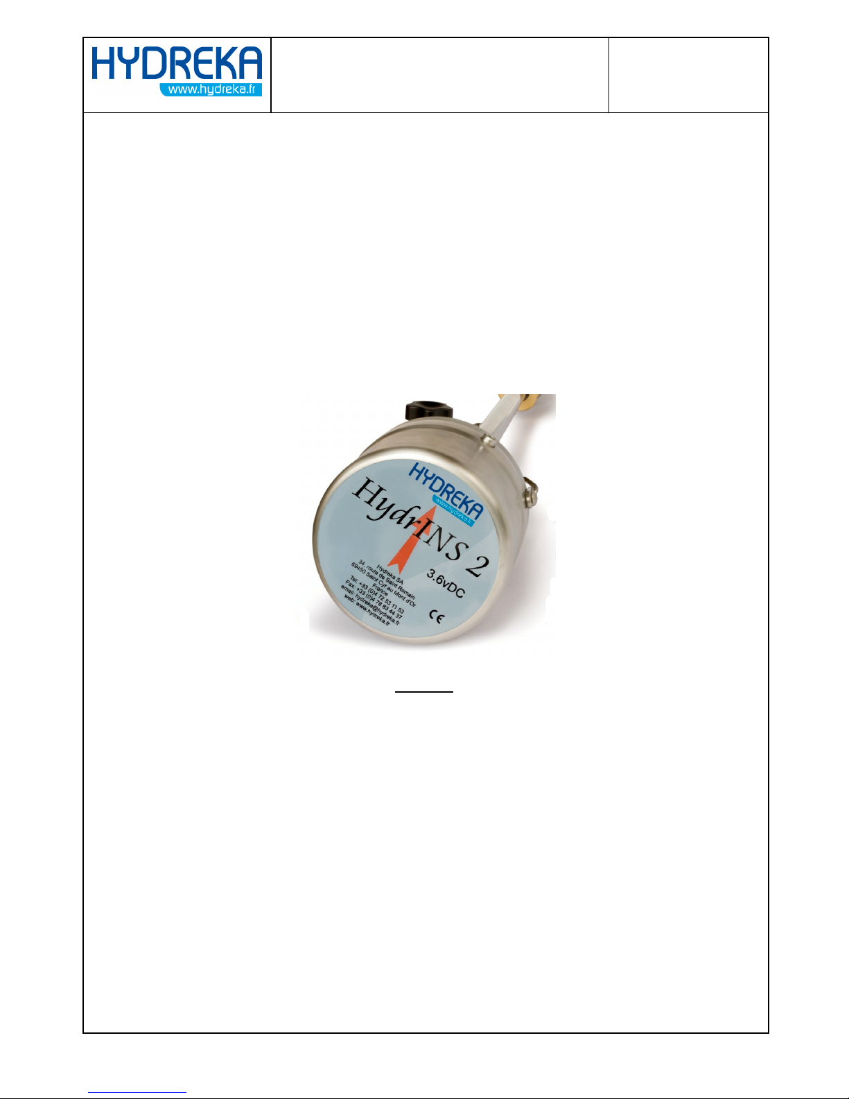
I ) HYDRINS 2 : CHANGE OF MODE (WITH OR WITHOUT DISPLAY) .............. 3
I.1 ) Tools ........................................................................................................................................................... 3
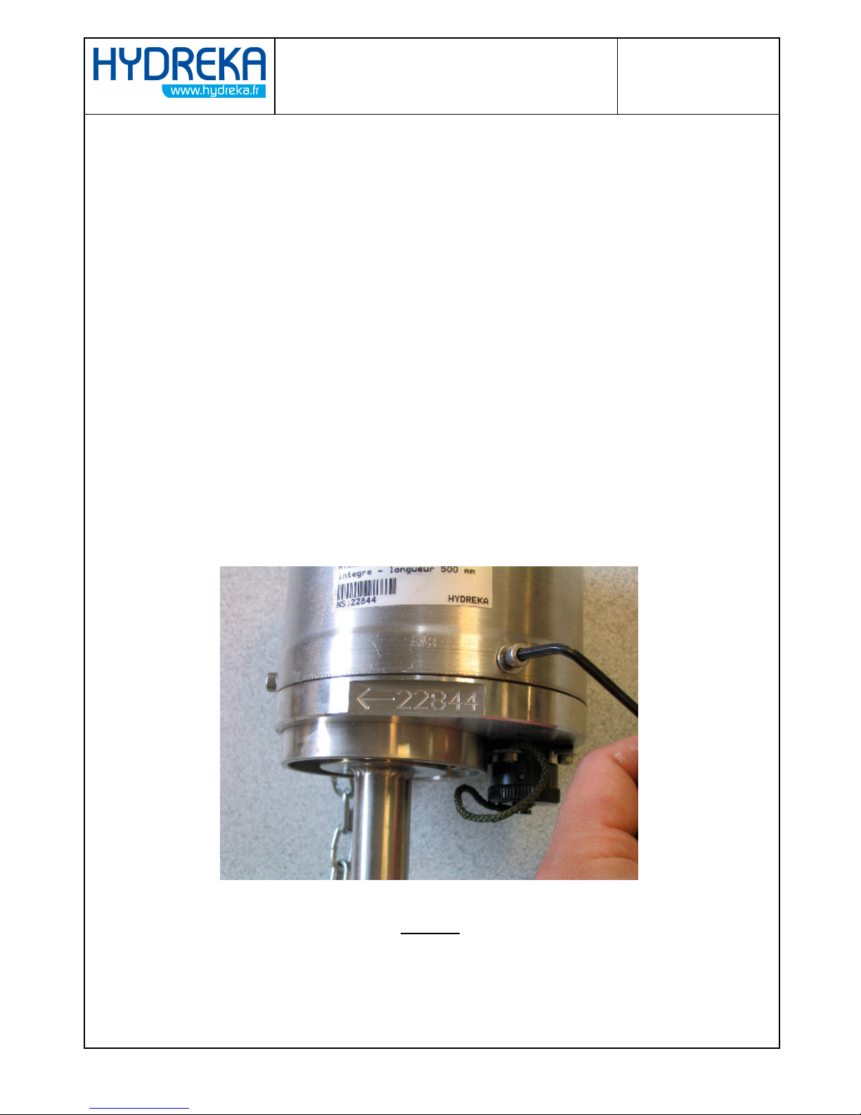
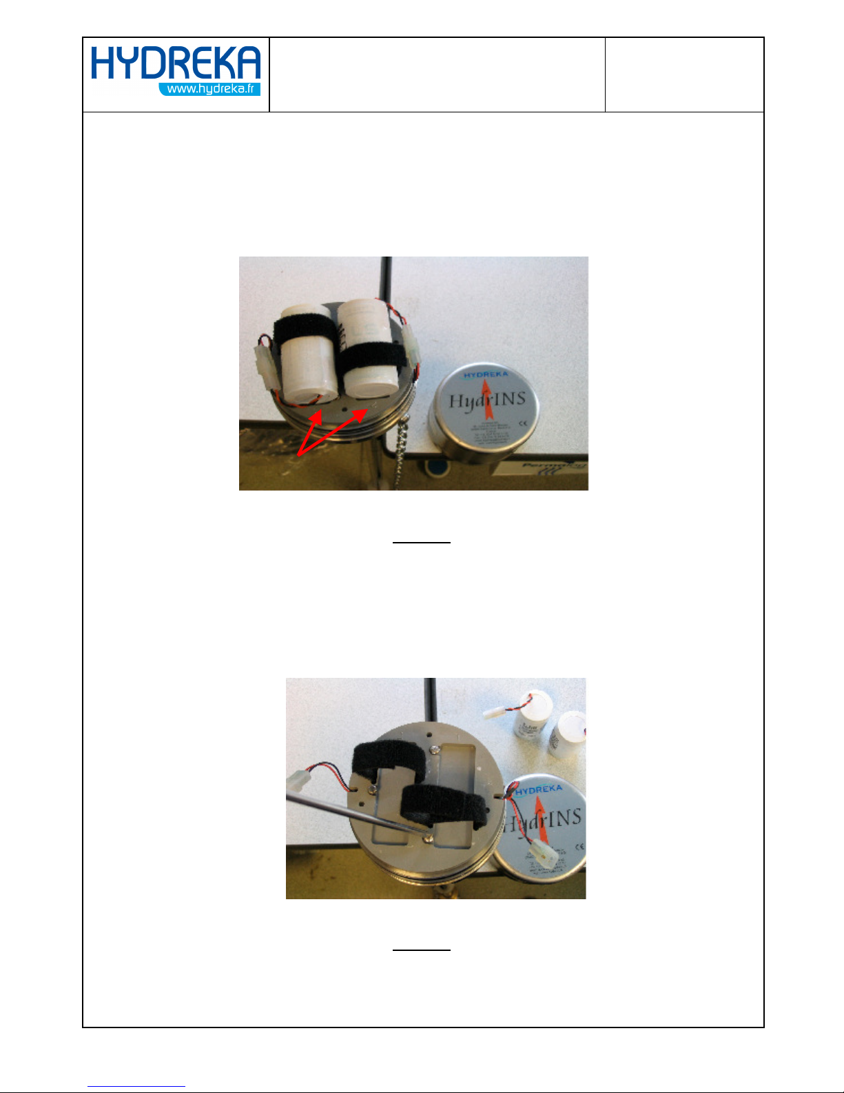
I.2 ) Disasse bling ............................................................................................................................................ 3
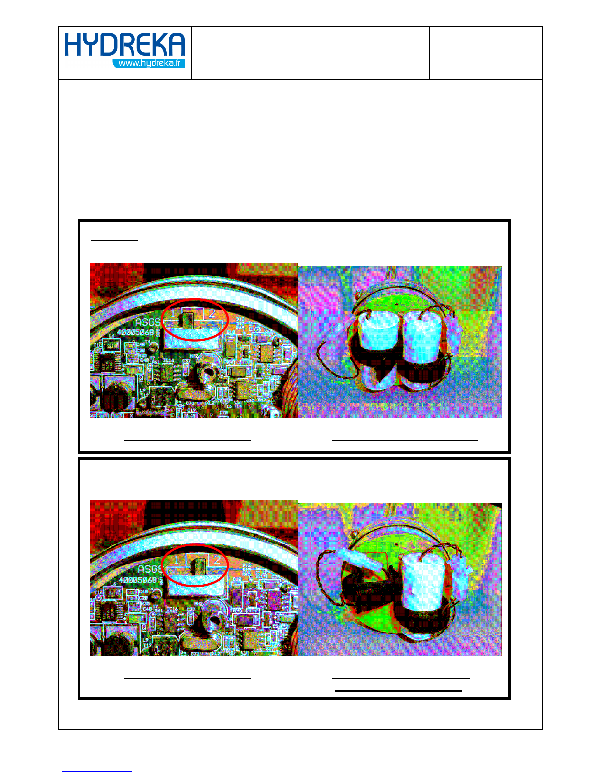
I.3 ) Change of MODE...................................................................................................................................... 5
I.4 ) Reasse bling ............................................................................................................................................. 6
II ) DISPLAY : LITHIUM BATTERIES TO EXTERNAL POWER SUPPLY .......... 6
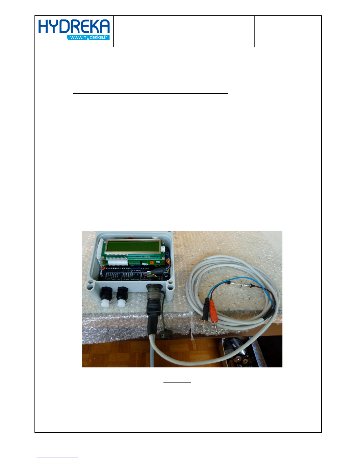
II.1 ) External power supply with internal connection (6-28V).................................................................. 7
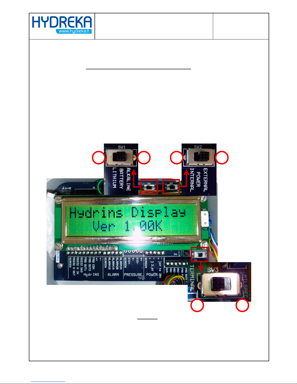
II.1.a ) Configuration of switches SW1, SW2 et SW3..................................................................................... 7
II.2 ) External power supply with the ilitary connector (6-28V) ............................................................. 9
II.2.a ) Configuration of switches SW1, SW2 et SW3..................................................................................... 9
III ) DISPLAY : EXTERNAL POWER SUPPLY TO LITHIUM BATTERIES ........ 10
III.1 ) Configuration of switches SW1, SW2 et SW3.................................................................................. 10
IV ) DISPLAY : EXTERNAL POWER SUPPLY FOR 4-20 mA OUTPUT TO
LITHIUM BATTERIES FOR PULSE OUTPUT......................................................... 11
IV.1 ) Disable the 4-20 A function ............................................................................................................. 11
IV.2 ) Configuration of switches SW1, SW2 et SW3.................................................................................. 12

CHANGES OF MODE AND POWER SUPPLY
OF THE HYDRINS 2 AND ITS DISPLAY
- Page 3 -
I ) HydrINS 2 : change of MODE (with or without display)
I.1 ) Tools
•1 flat s rewdriver.
•1 Allen key of 4
I.2 ) Disassembling
•Remove the three s rews on the ir umferen e of the probe head (Allen
s rews of 4) (Cf. Pi ture 1).
Picture 1

CHANGES OF MODE AND POWER SUPPLY
OF THE HYDRINS 2 AND ITS DISPLAY
- Page 4 -
•Remove the stainless steel head and the batteries. Be areful not to tear
off the wires and identify the battery 1 and the battery 2 as it is indi ated
on the battery support (Cf. Pi ture 2).
Picture 2
•Uns rew the three s rews, whi h hold the battery support and
remove it (Cf. Pi ture 3).
Picture 3

CHANGES OF MODE AND POWER SUPPLY
OF THE HYDRINS 2 AND ITS DISPLAY
- Page 5 -
I.3 ) Change of MODE
The hange of mode determining the use or not of the display, please respe t the onfiguration
of the probe (swit h and batteries) as des ribed below.
•Having now a ess to the ele troni board, change the position of the switch
according to the desired MODE (Cf. Pictures 4 et 6).
MODE 1 : WITHOUT display
Picture 4 switch position 1
Picture 5 2 batteries connected
MODE 2 : WITH display
Picture 6 switch position 2
Picture 7 1 battery connected
+ link connectors position 2

CHANGES OF MODE AND POWER SUPPLY
OF THE HYDRINS 2 AND ITS DISPLAY
- Page 6 -
I.4 ) Reassembling
•Reassemble the batteries support with its three s rews and be areful not to pin h the
wires (Cf. Pi ture 3)
•Reconnect the batteries depending on the ode you are using (Cf. Pictures 5 et 7).
•Repla e the head respe ting the dire tion of the red arrow (top fa e) with the one on
the side(Cf. Pi tures 1 et 8).
• If ne essary, you an use grease to set the O-ring.
Picture 8
• Finish by tightening (not too mu h) the three s rews of the head (Cf. Pi tures 1).
II ) Display : Lithiu batteries to external power supply
To pass from a Lithium Battery to an external power supply (battery lead, stabilized power
supply) just remove the Lithium pa k, set the swit hes, and then onne t the external power
supply either by internal onne tion on onne tor blo k or while passing by the military
onne tor as des ribe below.

CHANGES OF MODE AND POWER SUPPLY
OF THE HYDRINS 2 AND ITS DISPLAY
- Page 7 -
II.1 ) External power supply with internal connection (6-28V)
II.1.a )
Configuration of switches SW1, SW2 et SW3
Put SW1 in position 2
2
:
: ALKALINE
Put SW2 in position 2
2
:
: EXTERNAL
Put SW3 in position 1
1 : TERMINAL
Cf. Pi ture 9 for the position numbers.
1
2
1
2
1
2
Picture 9
SW1 SW2
SW3

CHANGES OF MODE AND POWER SUPPLY
OF THE HYDRINS 2 AND ITS DISPLAY
- Page 8 -
•You an now pass the ele tri able on the able gland provided for this purpose
and to onne t your sour e on the « + » and « - » onne tor blo k POWER « 6V
to 28V » (Cf. Pi tures 10 et 11).
Picture 10
Picture 11

CHANGES OF MODE AND POWER SUPPLY
OF THE HYDRINS 2 AND ITS DISPLAY
- Page 9 -
II.2 ) External power supply with the military connector (6-28V)
II.2.a ) Configuration of switches SW1, SW2 et SW3
Put SW1 in position 2
2
:
: ALKALINE
Put SW2 in position 2
2
:
: EXTERNAL
Put SW3 in position 2
2 : MILSPEC
Cf. Pi ture 9 for the position numbers.
•You an now supply the display by the military onne tor with an adequate able
(CNT104 or CNT105 for example) (Cf. Pi ture 12).
Picture 12

CHANGES OF MODE AND POWER SUPPLY
OF THE HYDRINS 2 AND ITS DISPLAY
- Page 10 -
III ) Display : External power supply to lithiu batteries
Opposite pro edure of what we have just seen, so it is ne essary to dis onne t the external
power supply, to hange the position of the swit hes (see below) and to onne t the lithium
pa k.
III.1 ) Configuration of switches SW1, SW2 et SW3
Put SW1 in position 1
1
:
: LITHIUM
Put SW2 in position 1
1
:
: INTERNAL
Put SW3 in position 1
1 : TERMINAL
Cf. Pi ture 9 for the position numbers.
•Conne t now your lithium pa k to the internal onne tor (Cf. pi ture 13).
Picture 13

CHANGES OF MODE AND POWER SUPPLY
OF THE HYDRINS 2 AND ITS DISPLAY
- Page 11 -
IV ) Display : External power supply for 4-20 A output to
lithiu batteries for pulse output
Same pro ess that previously. However, some onne tors must be moved in order to disable
the 4-20 mA fun tion.
IV.1 ) Disable the 4-20 mA function
•Dis onne t the power supply before exe uting the following things.
•Uns rew the 4 s rews whi h retain the display board and swing it gently forward to
a ess the two onne tors J1 et J2 of the 4-20mA board (Cf. Pi tures 14 et 15).
Picture 14

CHANGES OF MODE AND POWER SUPPLY
OF THE HYDRINS 2 AND ITS DISPLAY
- Page 12 -
Picture 15
•Dis onne t the onne tor J2 of the 4-20mA board and onne t it on the
motherboard J4 onne tor. Keep J1 dis onne ted (Cf. Pi ture 16).
Picture 16
•And finally reassemble the display board with its 4 s rews.
IV.2 ) Configuration of switches SW1, SW2 et SW3
Put SW1 in position 1
1
:
: LITHIUM
Put SW2 in position 1
1
:
: INTERNAL
Put SW3 in position 1
1 : TERMINAL
Cf. Pi ture 9 for the position numbers.
•Conne t now your lithium pa k to the internal onne tor (Cf. pi ture 13).
J1 J2
J1
J4
J2
Other manuals for HYDRINS 2
2
Table of contents
Popular Power Supply manuals by other brands

Keysight Technologies
Keysight Technologies E36300 Series Security guide

Xavax
Xavax Universal Operating instruction and service instructions

Moog
Moog G396-026 Operation manual

Communica
Communica PSU CCTV 12VDC 3,5A quick start guide

Notifier
Notifier HLSPS25-XP user manual

Versitron
Versitron AC300WR Technical manual