NOTE: HYDREL RESERVES THE RIGHT TO MODIFY SPECIFICATION
WITHOUT NOTICE. Any dimension on this sheet is to be assumed as a
reference dimension: “Used for information purposes only. It does not
govern manufacturing or inspection requirements.” (ANSI Y14.5-1973)
4600 KM
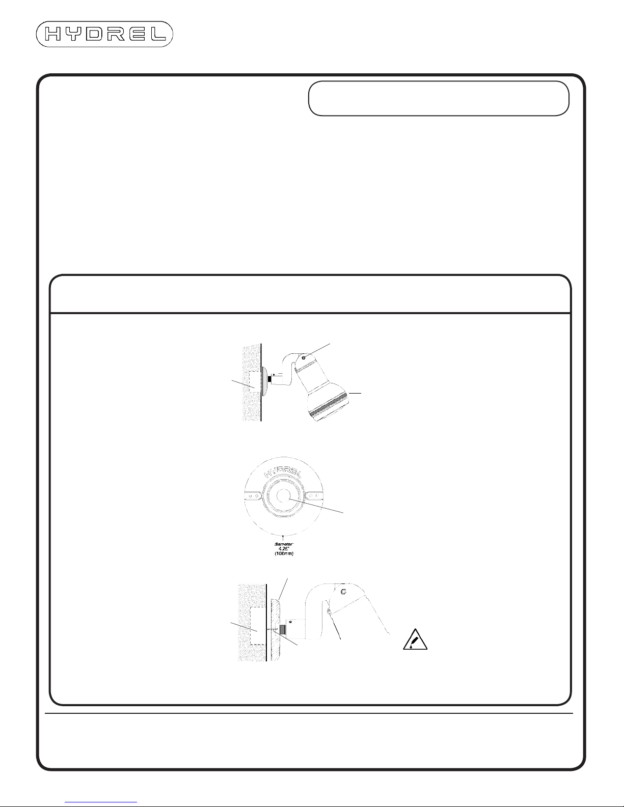
KNUCKLE MOUNT
INCANDESCENT (or fixture head only)
1. Be sure power is turned off.
2. Loosen knuckle stem set screws - Remove stem from
knuckle
3. Install stem to J-box cover using thread sealing com-
pound on threads to insure watertightness (masonry
or earth only).
4. Re-Install knuckle over stem, inserting cable through
stem opening. Snug set screws.
5. Install J-box gasket on box.
6. *Make electrical connections.
7. Install J-box cover and fixture to J-box. Tighten
screws evenly.
8. Aim fixture and retighten knuckle bolt.
9. Unscrew lens cover. Install lamp (by others) in
socket. Replace Lens cover. Take care not to cross
thread lens cover when tightening.
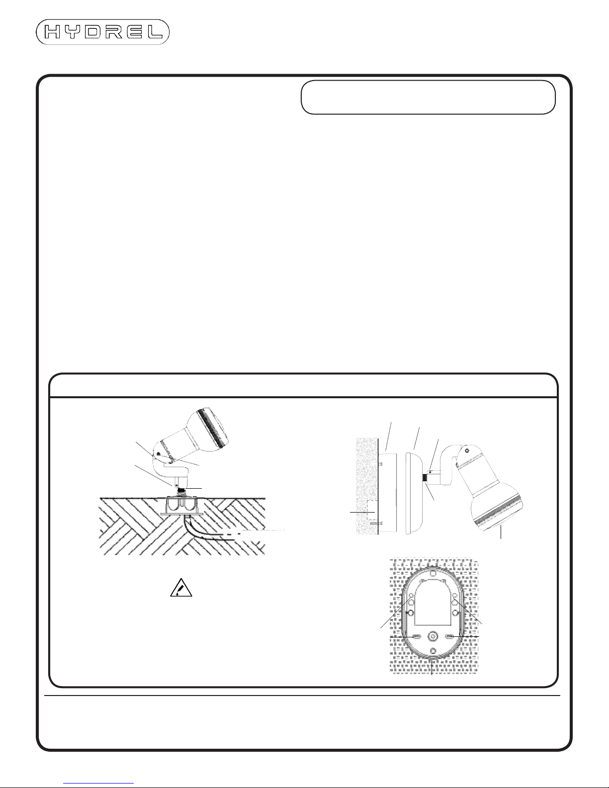
HID (over recessed wall box)
1. Be sure power is turned off.
2. Attach fixture to Ballast box cover plate. (See “fixture
KNUCKLE STEM
SET SCREWS (2)
KNUCKLE STEM
head only” directions)
3. Pull wires from wall box through hole in back of Bal-
last box.
4. Attach the Ballast box to the wall using suitable
screws (screws by others). Be sure to seal around
mounting screws to prevent water entry.
5. *Make electrical connections to the fixture. Attach
supply line wire to the wire labeled LINE from the Bal-
last box. Connect the Neutral wire from the supply to
the white wire in the
Ballast Box. Be sure that the ground wire is attached
to an approved grounding source.
6. Attach the fixture and cover plate to the Ballast box
using the screws provided
7. Loosen bolt in knuckle and knuckle stem set screws
to aim fixture. When aimed properly, retighten the
knuckle bolt and set screws.
8. Unscrew lens cover. Install lamp (by others) in socket.
Replace lens cover.
Note: Use only manufacturer recommended lamps.
BALLAST BOX BALLAST BOX
COVER PLATE
FIXTURE HEAD
WALLBOX
(by others)
KNUCKLE STEM SET SCREWS (2)
KNUCKLE STEM
SSB BALLAST BOX
MOUNTING
SCREWS
MOUNTING
SCREWS
INSTALLATION DIAGRAM
INSTALLATION INSTRUCTIONS Installation should be performed by a qualified
electrician in accordance with the National Electrical Code
and relevant local codes.
*IMPORTANT:
Junction Box/Ballast Box must be water tight.
Seal all conduit entries with suitable compound
(e.g. Hydrel PC-21 re-enterable potting compound)
to prevent moisture penetration from the supply
conduit system.
©2014 Acuity Brands Lighting, Inc.
6/19/14
INS-4600_KM
9144 Deering Avenue | Chatsworth, CA 91311
Phone: 866.533.9901 | Fax: 866.533.5291
www.hydrel.com
TO SUPPLY
BOLT
ADJUSTABLE
KNUCKLE
FINISH GRADE