Hydro-Gear 310-1500 Installation and operating manual

310-1500/310-1700
Integrated Hydrostatic Transaxle
Service and Repair Manual
BLN-52178
December 2008
Digitally signed by WMV-Dresden
DN: cn=WMV-Dresden, c=DE,
o=WMV-Dresden,
Date: 2017.01.26 09:49:46 +01'00'
WMV-
Dresden

TABLE OF CONTENTS
Section Page
Foreword .............................................................................................................................. 1
Description and Operation ................................................................................................. 2
Introduction.......................................................................................................................... 2
General Description ..................................................................................................................................... 2
Introduction .................................................................................................................................................. 2
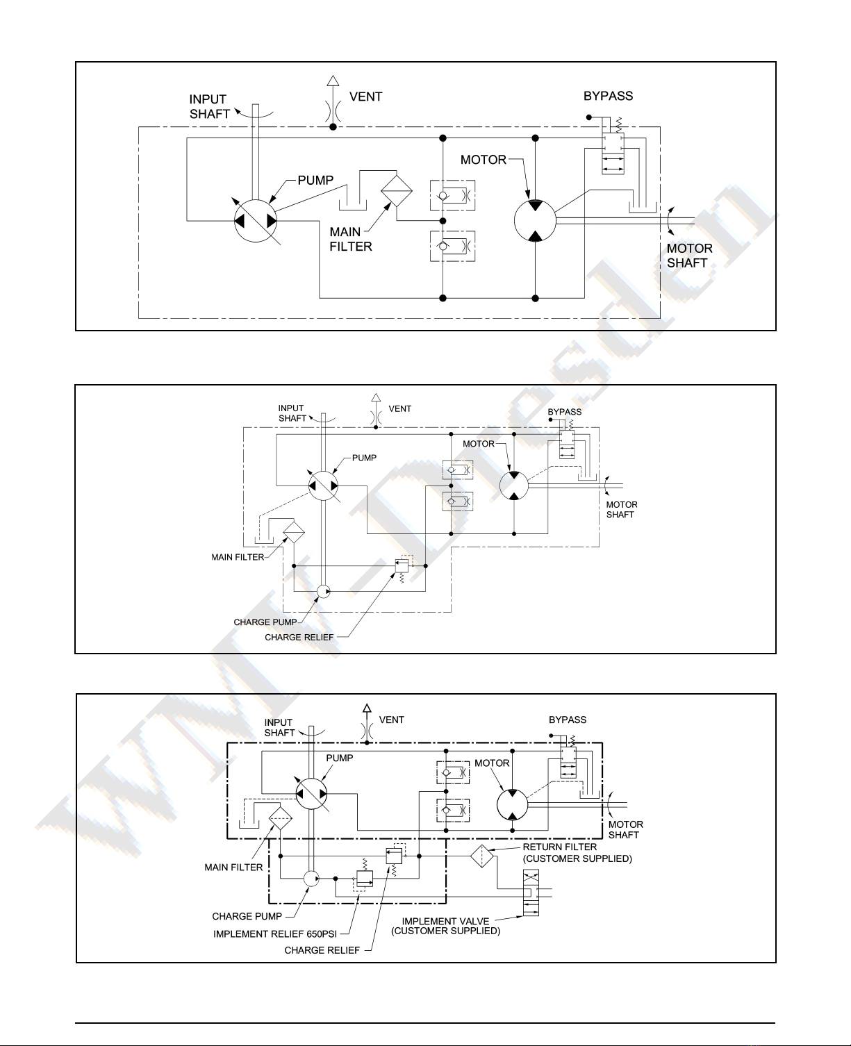
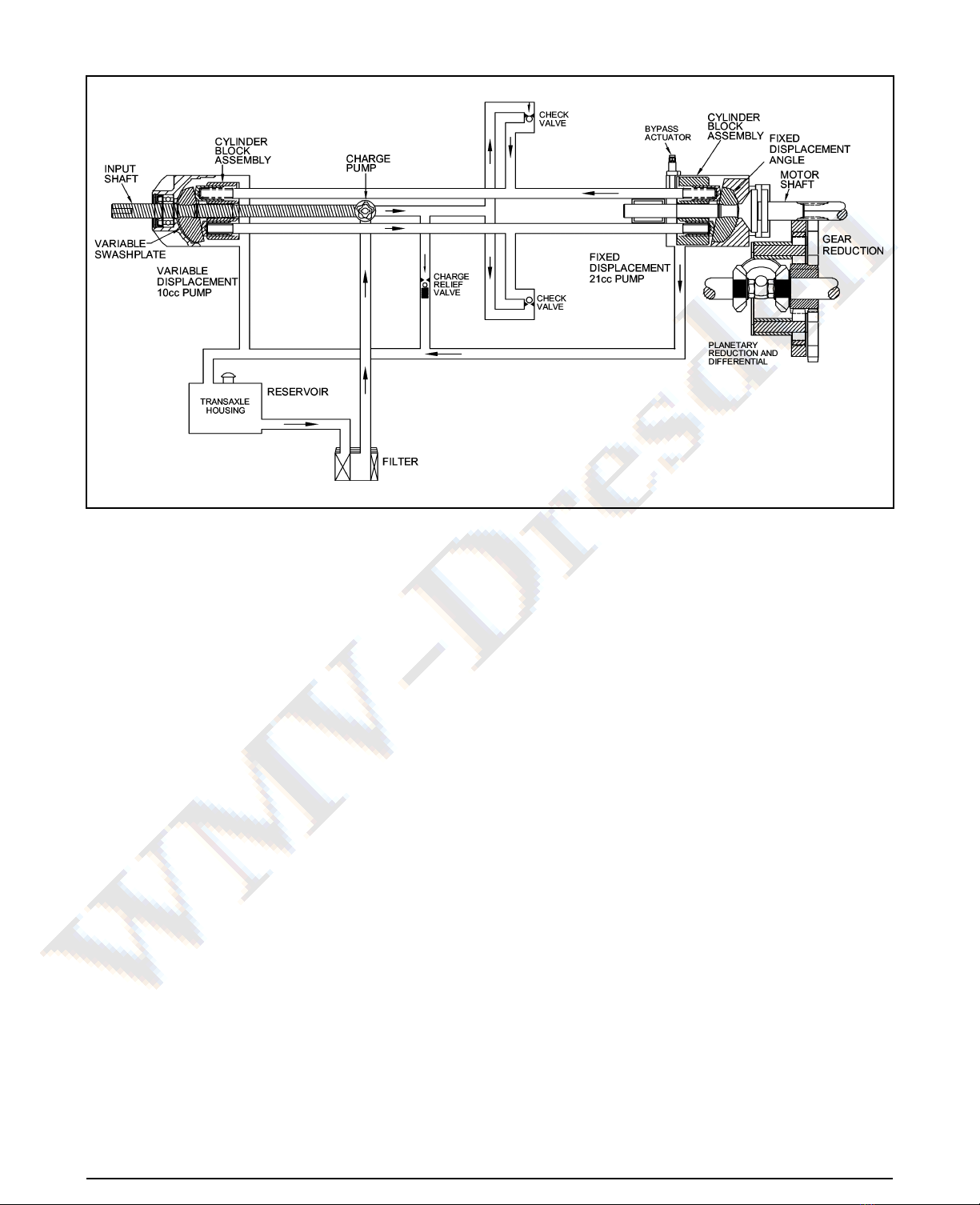
Hydraulic Schematic ................................................................................................................................. 3-5
Product Identification ................................................................................................................................... 6
Technical Specifications............................................................................................................................... 7
Safety.................................................................................................................................... 8
Personal Safety............................................................................................................................................ 8
Tool Safety ................................................................................................................................................... 8
Work Area Safety ......................................................................................................................................... 8
Servicing Safety ........................................................................................................................................... 8
Troubleshooting .................................................................................................................. 9
Service and Maintenance.................................................................................................. 10
External Maintenance ................................................................................................................................ 10
Service and Maintenance Procedures ....................................................................................................... 10
Fluids ..........................................................................................................................................................11
Brake Maintnenance .................................................................................................................................. 12
Return to Neutral Setting Foot Control....................................................................................................... 13
Purging Procedures ................................................................................................................................... 14
Repair ................................................................................................................................. 15
General Instructions................................................................................................................................... 15
Required Tools ........................................................................................................................................... 15
Torque Specifications................................................................................................................................. 15
Transaxle Removal .................................................................................................................................... 15
Limited Disassembly .................................................................................................................................. 15
How To Use This Manual ........................................................................................................................... 16
Brake Assembly .................................................................................................................................... 17,18
Bypass Assembly....................................................................................................................................... 19
Control Assembly .................................................................................................................................. 20,21
Seal Kit Replacement ................................................................................................................................ 22
Torque Bracket Assembly .......................................................................................................................... 23
Fan and Pulley Assembly........................................................................................................................... 24
Input Shaft Assembly ................................................................................................................................. 25
Auxiliary Pump ........................................................................................................................................... 26
Charge Pump Assembly ............................................................................................................................ 27
Lower Housing/FIlter/Manifold Assembly.............................................................................................. 27,29
Planetary Differential Assembly ............................................................................................................ 30-33
Motor/Center Section/Pump Assembly ................................................................................................. 34-36
Directional Control Assembly ..................................................................................................................... 37
Transaxle Installation ................................................................................................................................. 38
Assembly After a Complete Teardown ....................................................................................................... 38
Sealant Application .................................................................................................................................... 39
Parts List ....................................................................................................................... 40-43
Glossary of Terms ........................................................................................................ 44,45

-1500/-1700 IHT 1
FOREWORD
Headquartered in Sullivan, Illinois, Hydro-Gear®
is a world leader in the design, manufacture,
and service of quality hydrostatic transaxles for
the lawn and garden industry. The mission of
our company is to be recognized by our custom-
ers and the industry as a world-class supplier
and the quality leader in everything we do.
This Service and Repair Manual is designed
to provide information useful in servicing and
troubleshooting the Hydro-Gear -1500 or -1700
Integrated Hydrostatic Transaxle (IHT).
Also included is a glossary of terms that are
frequently used throughout the industry and
in Hydro-Gear service publications. Under-
standing terminology is very important!
It is necessary, and a good shop practice, that
your service area be equipped with the proper
tools and the mechanics be supplied the latest
information available. All repair procedures il-
lustrated in this guide are suggested, but pre-
ferred methods of repair.
Repair procedures require that the transaxle
unit be removed from the vehicle.
This is not a certification, test or study guide for
a certification test. If a technician is interested
in certification, they should contact an agent
representing the OPEESA (Outdoor Power
Equipment and Engine Service Association)
at (860) 767-1770 or their Hydro-Gear Central
Service Distributor. Many distributors will be
hosting certification testing. These study guides
will cover most of the products and manufac-
turers in our industry.
For more information about Hydro-Gear or our
products, please contact your Central Service
Distributor, or call our Customer Service De-
partment at (217) 728-2581.

2-1500/-1700 IHT
INTRODUCTION
The purpose of this manual is to provide use-
ful information for servicing the Hydro-Gear®
-1500/ -1700 Integrated Hydrostatic Transaxles
(IHT). This manual includes transaxle gen-
eral description, hydraulic schematic, technical
specifications, product identification, safety,
troubleshooting, maintenance, and repair pro-
cedures.
The transaxle normally will not require servic-
ing during the life of the vehicle in which it is
installed. Should other servicing be required,
the transaxle will need to be thoroughly cleaned
before beginning most procedures.
Please refer to the instructions titled “How to
Use This Manual” in the Repair Section for an
explanation of the layout of the disassembly,
inspection, and reassembly portions of this
manual.
GENERAL DESCRIPTION
The -1500/-1700 series transaxles are self con-
tained units designed for the transfer and con-
trol of power. They provide an infinitely variable
speed range between zero and maximum in
both forward and reverse modes of operation.
The transaxle uses a variable displacement
pump with a maximum displacement of 10
cc per revolution, and motor with a fixed dis-
placement of 21cc per revolution. The variable
displacement pump features a cradle swash-
plate with a direct-proportional displacement
control. Reversing the direction of the swash-
plate reverses the flow of oil from the pump
and thus reverses the direction of the motor
output rotation. The pump and motor are of the
axial piston design and utilize spherical nosed
pistons which are held against a thrust race by
internal compression springs.
The -1500/-1700 series transaxles have a self
contained fluid supply and an internal filter. The
fluid is drawn through the internal reservoir and
feeds the fixed displacement gerotor charge
pump. Excess fluid in the charge circuit is dis-
charged over the charge relief valve and dumps
back to case. Charge check valves in the center
section are used to control the makeup flow of
the fluid to the low pressure side of the loop.
The transaxle is filled and tested at the factory
and should not require fluid or filter changes
unless the fluid becomes contaminated.
A cam style, block lifting bypass is utilized in the
-1500/-1700 series to permit moving the vehicle
for a short distance at a maximum speed of 2
m.p.h. (3.2 km/hr) without starting the engine.
WARNING
Actuating the bypass will result in the
loss of hydrostatic braking capacity. The
machine must be stationary on a level
surface and in neutral when actuating
the bypass.
The -1500/-1700 series transaxles utilize an
in-line floating disc brake controlled by a "cam"
style actuating arm.
SECTION 1. DESCRIPTION AND OPERATION

-1500/-1700 IHT 3
Figure 1. -1500 Hydraulic Schematic
HYDRAULIC SCHEMATIC
Figure 2. -1700 Hydraulic Schematic
Figure 3. -1700 Hydraulic Schematic with Auxiliary Pump

4-1500/-1700 IHT
HYDRAULIC SCHEMATIC
Figures 4 and 5 provide illustrations of the hy-
draulic oil circuit. The oil supply for the hydraulic
system of the IHT is also utilized for the lubri-
cation of the planetary differential drive gears.
The input shaft and pump cylinder block are
turned in one direction only by the engine/drive
belt/pulley combination. Output of the oil flow
is controlled by the direction and amount that
the swashplate is angled. As the pump pistons
compress they force the oil to flow through one
of two passageways (forward or reverse) in
the center section (or valve body) to the motor
cylinder block and motor shaft. Since the mo-
tor has a fixed displacement angle it is forced
to turn with the flow of oil. As the angle of the
swashplate is increased the amount of oil being
pumped will increase and cause a higher RPM
output of the motor. Reversing the angle of the
pump swashplate will reverse the direction of
oil flow.
During the operation of the transaxle, fluid
is “lost” from the hydraulic loop through leak
paths designed into the product for lubrication
purposes (around pistons, under the rotating
cylinder blocks, etc.). This “lost” fluid returns
Figure 4. -1500 Hydraulic Flow Illustration
to the transmission housing and must be made
up in the loop. A charge pump is included on
the IHT to supply this makeup flow. The make
up flow is controlled (or directed) by the check
valves. Each check valve will either be held
opened or closed (depending upon the direction
of vehicle operation) by the system operating
pressure (closed) or by charge pressure (open)
from the charge pump.
The charge pump maintains a continuous flow
of oil as long as the input shaft is turning. All of
the oil being pulled into the charge pump first
must pass through an internal filter. Any oil not
needed by the transmission for make up flow
is discharged through the charge relief valve.
The charge relief valve maintains the charge
pressure.
The motor cylinder block mounts onto the
splined motor shaft which drives the planetary
differential gear/differential assembly.
The bypass feature in the IHT has a mechanical
lever which lifts the motor block off of the center
section running surface, allowing any oil flowing
from the pump block to be discharged into the
housing without turning the motor.

-1500/-1700 IHT 5
HYDRAULIC SCHEMATIC
Figure 5. -1700 Hydraulic Flow Illustration

6-1500/-1700 IHT
EXTERNAL FEATURES
-1500 AND -1700

-1500/-1700 IHT 7
TECHNICAL
SPECIFICATIONS
Technical specifications for the -1500 and -1700
IHT’s are given in Table 1.
Table 1. Technical Specifications
PRODUCT IDENTIFICATION
The model and configuration of the -1500 or
-1700 IHT can be determined from the label
shown in Figure 6.
Figure 6. -1700 Configuration Label
H Y D R O - G E A R
SULLIVAN, IL. U.S.A.
I IIIIIII IIII II II
165758 310-3000
I II IIII IIII IIIIII I II IIII
8 328
T1 476 Made in U.S.A.
Year Built
Date
(Julian - day of year)
Type of Product and Build Information
Serial Number
(unique number for that model - for that day)
OEM Model
Number
Hydro-Gear
Number
312-1700
Model
Number
Model
Reference
Number
-1500 -1700
Overall Transaxle
Reduction 24.6:1 24.6:1
Input Speed (rpm) 3000 max.
1800 min.
3600 max.
1800 min.
Maximum Tire Diameter 20 in. (508 mm) 23 in. (584 mm)
Axle Shaft Diameter 1.00 in. (25.4 mm) 1.00 in. (25.4 mm)
Axle Shaft End Options
4-Bolt Flange
Splined
4-Bolt Flange
Splined
Brake Type Disc Disc
Weight of Unit 53 lb. (24 kg) 53 lb. (24 kg)

8-1500/-1700 IHT
SECTION 2. SAFETY
PERSONAL SAFETY
Certain safety precautions must be observed
while servicing or repairing the IHT. This sec-
tion addresses some of these precautions but
must not be considered an all-inclusive source
on safety information. This section is to be
used in conjunction with all other safety material
which may apply, such as:
1) Other manuals pertaining to this ma-
chine
2) Local and shop safety rules and codes
3) Governmental safety laws and regu-
lations
Be sure that you know and understand the
equipment and the hazards associated with it.
Do not place speed above safety.
Notify your supervisor whenever you feel there
is any hazard involving the equipment or the
performance of your job.
Never allow untrained or unauthorized per-
sonnel to service or repair the equipment.
WARNING
POTENTIAL FOR SERIOUS INJURY
Inattention to proper safety, operation, or
maintenance procedures could result in
personal injury, or damage to the equip-
ment. Before servicing or repairing the
IHT, fully read and understand the safety
precautions described in this section.
Wear appropriate clothing. Loose or hanging
clothing or jewelry can be hazardous. Use the
appropriate safety equipment, such as eye
and hearing protection, and safety-toe and
slip-proof shoes.
Never use compressed air to clean debris from
yourself or your clothing.
TOOL SAFETY
Use the proper tools and equipment for the
task.
Inspect each tool before use and replace any
tool that may be damaged or defective.
WORK AREA SAFETY
Keep the work area neat and orderly. Be sure
it is well lit, that extra tools are put away, trash
and refuse are in the proper containers, and dirt
or debris have been removed from the working
areas of the machine.
The floor should be clean and dry, and all ex-
tension cords or similar trip hazards should be
removed.
SERVICING SAFETY
Certain procedures may require the vehicle to
be disabled in order to prevent possible injury
to the servicing technician and/or bystanders.
The loss of hydrostatic drive line power may
result in the loss of hydrostatic braking capabil-
ity. Proper brake maintenance is very important
should this condition develop.
Some cleaning solvents are flammable. Use
only approved cleaning materials: do not use
explosive or flammable liquids to clean the
equipment.
To avoid possible fire do not use cleaning sol-
vents in an area where a source of ignition may
be present
Discard used cleaning material in the appropri-
ate containers.
This symbol points out important
safety instructions which, if not followed, could
endanger the personal safety and/or property
of yourself and others. Read and follow all
instructions in this manual before attempting
maintenance on your transaxle. When you see
this symbol - HEED ITS WARNING.

-1500/-1700 IHT 9
WARNING
Do not attempt any servicing or ad-
justments with the engine running.
Use extreme caution while inspecting
the drive belt assembly, and all vehicle
linkage!
Follow all safety procedures outlined in
the vehicle owner’s manual!
SECTION 3. TROUBLESHOOTING
In many cases problems with the IHT are not re-
lated to a defective transmission or axle, but are
caused by slipping drive belts, partially engaged
bypass valves, and loose or damaged control
linkages. Be sure to perform all operational
checks and adjustments outlined in Section
4 before assuming the unit is malfunctioning.
Table 2 below provides a troubleshooting check
list to help determine the cause of operational
problems.
Possible Cause
Table 2. Troubleshooting Checklist
Corrective Action Refer To:
UNIT OPERATES IN ONE DIRECTION ONLY
Control linkage bent or out of adjustment
Drive belt slipping or pulley damaged
Repair or replace linkage
Repair or replace drive belt or pulley
UNIT IS NOISY
Oil level low or contaminated oil
Excessive loading
Brake setting incorrect
Loose parts
Bypass assembly sticking
Air trapped in hydraulic system
Fill to proper level or change oil
Reduce vehicle loading
Adjust brake to proper setting
Repair or replace loose parts
Repair or replace valve or linkage
Purge hydraulic system
UNIT HAS NO/ LOW POWER
Engine RPM low
Control linkage bent or out of adjustment
Brake setting incorrect
Drive belt slipping or pulley damaged
Oil level low or contaminated oil
Excessive loading
Bypass assembly sticking
Air trapped in hydraulic system
Adjust to correct setting
Repair or replace linkage
Adjust brake to proper setting
Repair or replace drive belt or pulley
Fill to proper level or change oil
Reduce vehicle loading
Repair or replace valve or linkage
Purge hydraulic system
UNIT OPERATING HOT
Debris buildup around transaxle
Brake setting incorrect
Cooling fan damaged
Oil level low or contaminated oil
Excessive loading
Air trapped in hydraulic system
Clean off debris
Adjust brake to proper setting
Repair or replace cooling fan
Fill to proper level or change oil
Reduce vehicle loading
Purge hydraulic system
TRANSAXLE LEAKS OIL
Damaged seals, housing, or gaskets
Air trapped in hydraulic system
Replace damaged component
Purge hydraulic system
Control Linkage Repair, Page 23
Pulley Repair, Page 27
Fluid Maintenance, Page 11
Vehicle Specifications
Brake Adjustment, Page 12
Appropriate Repair Procedure
Bypass Repair, Page 22
Purging Procedure, Page 15
Vehicle Specifications
Control Linkage Repair, Page 23
Brake Adjustment, Page 12
Pulley Repair, Page 27
Fluid Maintenance, Page 11
Vehicle Specifications
Bypass Repair, Page 22
Purging Procedure, Page 15
Brake Adjustment, Page 12
Cooling Fan Repair, Page 27
Fluid Maintenance, Page 11
Vehicle Specifications Purging
Procedure, Page 15
Appropriate Repair Procedure
Purging Procedure, Page 15

10 -1500/-1700 IHT
SECTION 4. SERVICE AND MAINTENANCE
NOTE: Any servicing dealer attempt-
ing a warranty repair must have prior
approval before conducting mainte-
nance of a Hydro-Gear®product un-
less the servicing dealer is a current
Authorized Hydro-Gear Service Center.
EXTERNAL MAINTENANCE
Reference Table 4., Page 16 for tools required
in the maintenance of the IHT.
Regular external maintenance of the IHT
should include the following:
1. Check the vehicle operator’s manual for
the recommended load ratings. Insure the
current application does not exceed load
rating.
2. Check oil level See Figure 7, Page 11.
3. Inspect the vehicle drive belt, idler pulley(s),
and idler spring(s). Insure that no belt slip-
page can occur. Slippage can cause low
input speed to the transaxle.
4. Inspect the transaxle cooling fan for bro-
ken or distorted blades and remove any
obstructions (grass clippings, leaves dirt,
etc.).
5. Inspect the axle parking brake and vehicle
linkage to insure proper actuation of the
parking brake.
6. Inspect the vehicle control linkage to the
directional control arm on transaxle. Also,
insure the control arm is securely fastened
to the trunnion arm of the transaxle.
7. Inspect the bypass mechanism on the trans-
axle and vehicle linkage to insure it actuates
and releases fully.
SERVICE AND
MAINTENANCE
PROCEDURES
All the service and maintenance procedures
presented on the following pages can be per-
formed while the transaxle is mounted on the
vehicle. Any servicing beyond those given must
be performed after the unit has been removed
from the vehicle. Additional procedures are
provided in Section 5. Repair Procedures.

-1500/-1700 IHT 11
FLUIDS
The fluids used in Hydro-Gear®products have
been carefully selected, and only equivalent, or
better products should be substituted.
Typically, an engine oil with a minimum rating of
9 cSt (55 SUS) at 230° F (110° C) and an API
classification of SJ/CD is recommended. A
20W-50 engine oil has been selected for use
by the factory and is recommended for normal
operating temperatures.
FLUID VOLUME
Fluid volume information is provided in Table
3.
FLUID LEVEL
Certain situations may require additional fluid to
be added or even replaced. Refer to Figure 3
for the proper fill port and fluid level port loca-
tions. Fill the unit until fluid flows out of the fluid
level port. Recheck the fluid level once the unit
has been operated for approximately 1 minute.
Purging may be required. Refer to the purging
procedures, Page 14.
FLUID CHANGE
This transaxle is factory filled and does not
require a regular oil change. In the event of
oil contamination or degradation an oil change
may improve performance.
Using the transaxle removal procedure from
Section 5, Page 15, remove the transaxle and
drain the oil from the top fluid fill port. Fill unit
per Table 3, reinstall the transaxle and perform
the purging procedures, Page 14.
In the event a fluid change and filter inspection
is required, refer to Page 27, Disassembly/As-
sembly instructions.
Caution
Do not overfill.
If you overfill the transaxle while the unit
is "cold", it may overflow as it reaches
normal operating temperatures. The oil
level should not be above the manu-
facturer’s suggestions outlined in this
manual. This will allow the space needed
for the oil to expand as it warms up.
Figure 7. -1500 and -1700 Fluid Fill and Level Ports
Fluid Description
20W-50 engine oil
Volume
124.4 fl.oz. (3680 ml) to 129.5 fl.oz. (3830 ml)
106.2 fl.oz. (3140 ml) to 110.8 fl.oz. (3280 ml)
Table 3. Fluid Volumes for the -1500 and -1700 IHT
Model
-1500
-1700

12 -1500/-1700 IHT
BRAKE MAINTENANCE
BRAKE SETTING
1. Remove the brake arm bias spring, and
then the cotter pin securing the brake castle
nut.
2. Insert a 0.015" (.381 mm) feeler gage be-
tween the brake disc and top brake puck,
and then set the brake by tightening or
loosening the castle nut.
3. Adjust brake gap to 0.015" (.381 mm) clear-
ance.
4. Install the cotter pin to secure the castle nut,
and then install the brake arm bias spring.

-1500/-1700 IHT 13
RETURN TO NEUTRAL SETTING
FOOT CONTROL
WARNING
POTENTIAL FOR SERIOUS INJURY
Certain procedures require the vehicle
engine to be operated and the vehicle to
be raised off of the ground. To prevent
possible injury to the servicing tech-
nician and/or bystanders, insure the
vehicle is properly secured.
The return to neutral mechanism on the trans-
mission is designed to set the directional con-
trol into a neutral position when the operator
removes their foot from the foot control. Follow
the procedures below to properly adjust the
return to neutral mechanism on the transaxle:
1. Confirm the transaxle is in the operating
mode (bypass disengaged). Raise the
vehicle’s drive tires off the ground to allow
free rotation.
NOTE: It may be necessary to remove
the drive tire from the axle hub to access
the linkage control and the transaxle
control arm.
2. Remove the Original Equipment Manufac-
turer’s (OEM’s) control linkage at the control
arm. Refer to Figure 9.
WARNING
Do not attempt any adjustments with the
engine running. Use extreme caution
while inspecting all vehicle linkage!
Follow all safety procedures outlined in
the vehicle owner’s manual!
3. Start the engine and increase the throttle to
full engine rpm.
4. Check for axle rotation. If the axles do not
rotate, go to Step 5. If the axles rotate, go
to Step 6.
5. Stop the vehicle’s engine. Adjust the OEM
linkage according to the OEM manual. Re-
check according to Step 3 and 4. Stop the
vehicle engine. Refer to Figure 9.
6. Note the axle directional movement . Stop
the vehicle engine. Loosen the adjusting
puck screw until the puck can be rotated.
Rotate the adjusting puck the opposite di-
rection of the wheel rotation on the control
linkage side in 5 degree increments. Tighten
the adjusting puck screw. Refer to Table 5.
Required Torque Values, Page 17. Recheck
according to Step 3 and 4. Stop the vehicle
engine. Adjust the OEM linkage according
to the OEM manual. Recheck according to
Step 3 and 4. Refer to Figure 9.
Figure 9. Return to Neutral, Foot Control

14 -1500/-1700 IHT
PURGING PROCEDURES
Due to the effects air has on efficiency in hy-
drostatic drive applications, it is critical that it
be purged from the system.
These purge procedures should be imple-
mented any time a hydrostatic system has
been opened to facilitate maintenance or any
additional oil has been added to the system.
Air creates inefficiency because its compres-
sion and expansion rate is higher than that of
the oil normally approved for use in hydrostatic
drive systems.
The resulting symptoms in hydrostatic systems
may be:
1. Noisy operation
2. Lack of power or drive after short term op-
eration
3. High operation temperature and excessive
expansion of "oil", in the latter case, oil may
overflow.
Before starting, make sure the transaxle/ trans-
mission is at the proper oil level. If it is not, fill
to the manufacturers suggestions outlined in
the vehicle owners manual.
The following procedures should be per-
formed with the vehicle drive wheels off
the ground, then repeated under normal
operating conditions.
1. With the bypass valve open and the engine
running, slowly move the directional control
in both forward and reverse directions 6 to
10 times, as air is purged from the unit, the
oil level will drop and bubbles may appear in
the oil. After stopping the engine, add oil, as
necessary. Fill to the level outlined in Figure
7, Page 11.
2. With the bypass valve closed and the engine
running, slowly move the directional control
in both forward and reverse directions (6 to
10 times). Check the oil level, and add oil
as required after stopping engine.
3. It may be necessary to repeat Steps 1 and 2
until all the air is completely purged from the
system. When the transaxle moves forward
and reverse, purging is complete.
CAUTION
DO NOT OVERFILL.
If you overfill the transaxle while the unit
is "cold", it may overflow as it reaches
normal operating temperatures. The
oil level should not be above the level
shown in figure 7, Page 11. This will allow
the space needed for the oil to expand
as it warms up.

-1500/-1700 IHT 15
SECTION 5. REPAIR
NOTE: Any servicing dealer attempting
a warranty repair must have prior ap-
proval before conducting maintenance
of a Hydro-Gear®product unless the
servicing dealer is a current Authorized
Hydro-Gear Service Center.
GENERAL INSTRUCTIONS
Cleanliness is a primary means of assuring
satisfactory life on repaired units. Thoroughly
clean all exposed surfaces prior to any type
of maintenance. Cleaning of all parts by us-
ing a solvent wash and air drying is usually
adequate. As with any precision equipment, all
parts must be kept free of foreign material and
chemicals.
Protect all exposed sealing surfaces and open
cavities from damage and foreign material. The
external surfaces should be cleaned before be-
ginning any repairs.
Upon removal, it is recommended that all seals,
O-rings, and gaskets be replaced. During instal-
lation lightly lubricate all seals, O-rings, gaskets
with a clean petroleum jelly prior to assembly.
Also protect the inner diameter of seals by
covering the shaft with a cellophane (plastic
wrap, etc.).
Parts requiring replacement must be replaced
from the appropriate kits identified in the Items
Listing, found at the end of this manual.
REQUIRED TOOLS
A list of tools required for the repair of the -1500
or -1700 IHT is provided in Table 4, Page 17.
TORQUE SPECIFICATIONS
Torque specifications for fasteners used on the
-1500 and -1700 IHT are provided in Table 5.
TRANSAXLE REMOVAL
It is necessary to remove the -1500 or -1700
from the vehicle before performing the repair
procedures presented in this section. Use the
following procedure to prepare the unit for re-
moval from the vehicle.
1. With the vehicle wheels on the ground,
loosen the nut (119, Figure 29) Page 40,
retaining the hub (118, Figure 29) on the
control side of the transaxle only. Use an
air impact wrench and a 1-1/8” socket to
loosen the hub.
2. Lift the vehicle wheels from the ground and
remove the nut completely.
3. Remove the wheel from the hub.
4. Using a wheel or gear puller, remove the
hub from the shaft.
CAUTION
USE CARE IN REMOVING THE HUB TO
PREVENT CRACKING.
LIMITED DISASSEMBLY
The following procedures are presented in
the order in which they must be performed
to completely disassemble the unit. Do not
disassemble the unit any farther than is nec-
essary to accomplish the required repairs.
Each disassembly procedure is followed by a
corresponding assembly procedure, and the
disassembly process can be halted after any
given procedure.
Assembly is accomplished by performing the
assembly portions of the procedures. If the
unit has been completely disassembled, a
summary of the assembly procedures, in the
order in which they should occur, is given on
Page 38.

16 -1500/-1700 IHT
Miscellaneous
-1500/-1700 Service & Repair Manual
Loctite
Flat Blade Screw Driver
Torque Wrench
Air Impact Wrench
Pliers
Needle Nose
External Snap Ring
Internal Snap Ring
Allen Wrenches
5 mm, 6 mm, 1/4 inch
HOW TO USE THIS
MANUAL
Many of the parts and subassemblies of this
transaxle can be removed and serviced inde-
pendently of other components. The disas-
sembly, inspection, and assembly portions of
this manual are therefore laid out in subsec-
tions. Each assembly is treated as a unit, and
the disassembly, inspection, and assembly
procedures follow one another.
Where some components and assemblies must
be removed before a given assembly can be
serviced, that information is given at the be-
ginning of the disassembly instructions.
Subassemblies removed to reach another
component or feature need not be fully dis-
assembled. They may be reassembled intact
following the necessary repairs.
Each assembly is provided with an exploded
view showing the parts involved. At the end of
the manual, after the reassembly summary, a
complete exploded views and items lists are
provided.
Sockets
3/8" Drive: 7/16", 1/2", 13/16"
1/2” Drive: 9/16", 15/16", 1-1/8"
#8 Internal Torx Drive
#10 Internal Torx Drive
Socket Drivers
3/8", 1/2"
Combination Wrenches
7/16", 1/2", 9/16", 13/16", 15/16", 1-1/8"
Table 4. Required Tools
Operation Torque Item Description
Center Section Screws (Item #44) 525-700 lb-in (59-79 Nm) 44 Screw
Lower Housing Screws (Item # 50) 135-185 lb-in (15-21 Nm) 50 Screw
Charge Pump Cover Screws (Item # 29) 87-108 lb-in (9-12 Nm) 29 M6 x 1-22
Axle Shaft Jam Nut (Item # 73) 660-800 lb-in (75-90 Nm) 73 5/16-18
Right Hand Housing Screws (Item # 80) 230-290 lb-in (26-33 Nm) 80 5/16-18
Axle Hub Nut (Item # 119) 200-295 lb-ft (271-400 Nm) 119 3/4-16
Pulley Nut (Item # 115) 360-520 lb-in (41-59 Nm) 115 Jam Nut
Torque Bracket Nut (Item # 142) 160-210 lb-in (18-24 Nm) 142 5/16-18
Control Arm Stud (Item # 36) 50-120 lb-in (6-14 Nm) 36 5/16-24
Control Bearing Screw(Item # 92) 190-240 lb-in (22-27 Nm) 92 Screw
Control Arm Nut (Item # 95) 85-120 lb-in (10-14 Nm) 95 5/16-24
Adjusting Puck Screw (Item # 88) 250-320 lb-in (28-36 Nm) 88 5/16-24 x 1-3/4
Brake Nuts (Item # 127) 80-120 lb-in (9-14 Nm) 127 1/4-20
Differential Lock Sleeve Screws (Item #50) 135-185 lb-in (15-21 Nm) 50 Screw 1/4-20 x .75
Table 5. Required Torque Values

-1500/-1700 IHT 17
BRAKE ASSEMBLY
Refer to Figures 12 and 13.
DISASSEMBLY
1. Remove the cotter pin (129), castle nut
(128), and washer (77).
2. Remove brake arm (124), and brake arm
bias spring (141).
3. Remove brake anti-drag compression spring
(151), and two brake pins (125).
4. Remove upper bolt (121) which secures
brake yoke assembly (122).
5. Remove lower bolt (132), washer (139) and
spacer (130) which secure the brake yoke
assembly (122).
6. Remove brake yoke assembly (122), puck
plate (131), and outer brake puck (120).
7. Remove brake disc (85), and inner brake
puck (120).
Figure 12. Brake Assembly
REF. Part Name
129 Cotter Pin
130 Spacer
131 Puck Plate
132 Bolt
139 Washer
141 Brake Arm Bias Spring
151 Anti-Drag Compression
Spring
REF. Part Name
2 Right Hand Housing Assembly
77 Washer
85 Brake Disk
120 Brake Puck
121 Bolt
122 Brake Yoke Assembly
124 Brake Arm
125 Brake Pin
128 Castle Nut

18 -1500/-1700 IHT
INSPECTION
1. Inspect the brake pucks (120) for excessive
wear.
2. Replace with new if necessary.
ASSEMBLY
1. Install inner brake puck (120), and brake
disc (85).
2. Assemble the brake yoke assembly, by in-
stalling puck plate (131), outer brake puck
(120) into brake yoke (122).
3. Position the brake yoke assembly against
the brake disc.
4. Install the upper bolt (121).
5. Install the lower bolt spacer (130), washer
(139) and bolt (132) to secure the brake
yoke assembly (122).
6. Install brake anti-drag compression spring
(151), and two brake pins (125).
7. Install brake arm (124) onto brake yoke as-
sembly.
8. Install washer (77), and castle nut (128).
9. Insert a (0.015”) (.381 mm) feeler gage be-
tween brake disc (85) and outer brake puck
(120). Adjust the brake by turning castle nut
(128) until it is snug but not tight against the
feeler gage. (The brake gap must be ad-
justed to a (0.015”) (.381 mm) clearance.
10.Install cotter pin (129) to secure castle nut
(128).
11. Install brake arm bias spring (141) to brake
arm (124) and lower brake yoke assembly
bolt (132).
This manual suits for next models
1
Table of contents