manuals.online logo
Brands
  1. Home
  2. •
  3. Brands
  4. •
  5. Hydro Leduc
  6. •
  7. Water Pump
  8. •
  9. Hydro Leduc XR80 Installation manual

Hydro Leduc XR80 Installation manual

BP 9 - F 54122 Azerailles - France - Tel : (33) 03.83.76.77.40 - Fax : (33) 03.83.75.21.58 - www.hydroleduc.com - [email protected]
i
ALIRE IMPÉRATIVEMENTAVANT LE MONTAGE DE LA POMPE.
PLEASE READ BEFORE INSTALLING THE PUMP.
BITTE ANLEITUNG VOR INBETRIEBNAHME LESEN.
NOTICE DE MISE EN ROUTE
START-UP INSTRUCTIONS
BETRIEBSANLEITUNG
Art. : NOTXR001_A
XR80
BP 9 - F 54122 Azerailles - France - Tel : (33) 03.83.76.77.40 - Fax : (33) 03.83.75.21.58 - www.hydroleduc.com - [email protected]
2
FR EN DE
1 - CONTROLE DU SENS
DE ROTATION DE LA PRISE DE
MOUVEMENT
S’assurer que les caractéristiques
techniques entre la pompe et la PMT
soient compatibles.
1 - CHECKING THE DIRECTION OF
ROTATION OF THE PTO
Make sure that the technical
specications between the pump and
the PTO are compatible.
1 - PRÜFEN SIE DIE
ERFORDERLICHE PLATZIERUNG
DES SAUGSTUTZENS
IN ABHÄNGIGKEIT DER
DREHRICHTUNG DER PUMPE
Stellen Sie sicher, dass die technischen
Spezikationen zwichen Pumpe und
Nebenantrieb geeignet sind.
2 - MODIFICATION DU SENS DE
ROTATION DE LA POMPE XR80
Exemple pour changer une pompe SH
en version SIH :
a - Sortie d’usine, la pompe est
programmée pour fonctionner en
rotation droite (SH)
b- Assurez-vous que la pompe soit
bien maintenue (dans un étau) avec la
culasse vers le haut, puis desserrer les
4 vis de la culasse.
c - Faites pivoter la culasse de 180°.
Attention à ne pas soulever la
culasse pendant cette opération.
d- Positionner les vis correctement
en fonction du sens de rotation (voir
illustration), et remonter les vis avec les
rondelles freins.
e- Serrer la culasse avec un couple
sur les vis de 10 m.daN.
2 - CHANGING THE DIRECTION OF
ROTATION OF THE XR80 PUMP
Example to change from CW to CCW
version :
a - When it leaves the factory, the
pump is programmed to rotate in
clockwise rotation
b - Make sure that the pump is held
rmly (in a vice) with the back cover
facing upwards, then loosen the 4
screws.
c - Rotate the back cover through 180°.
Be careful not to lift the back cover
during this operation.
d - Position the screws correctly
according to the direction of rotation
(see pictures), and reassemble the
screws with lock washers.
e - Tighten the back cover with a
tightening torque on the screws of 10
m.daN.
2 - ÄNDERUNG DER
DREHRICHTUNG DER XR80 PUMPE
Beispiel zur Umstellung der
Drehrichtung von CW (rechts drehend)
auf CCWS (links drehend) :
a - Die Werkseinstellung
(Auslieferzustand) der Pumpe ist immer
CW (rechts drehend).
b - Stellen Sie sicher, dass das
Pumpengehäuse fest eingespannt
(xiert) ist und dass die Rückplatte der
Pumpe nach oben zeigt. Lösen Sie
dann die 4 Befestigungsschrauben der
Rückplatte.
c - Drehen Sie die Rückplatte der Pumpe
um 180°.
Achten Sie hierbei darauf, dass
die Rückplatte immer Kontakt
zum Pumpengehäuse behält und
heben Sie die Rückplatte niemals
komplett ab.
d - Platzieren Sie die Schrauben
entsprechend der eingestellten
Drehrichtung (siehe Bild) und ziehen
Sie die Schrauben mit Konterscheibe
wieder fest.
e - Das Anzugsdrehmoment hierbei
betgrägt 100 Nm.
INSTRUCTION DE MONTAGE | INSTALLATION PROCEDURE | ANWEISUNGEN
BP 9 - F 54122 Azerailles - France - Tel : (33) 03.83.76.77.40 - Fax : (33) 03.83.75.21.58 - www.hydroleduc.com - [email protected]
3
INSTRUCTION DE MONTAGE | INSTALLATION PROCEDURE | ANWEISUNGEN
SH / CW
SIH / CCW
1
SH / CW
a
c
b
d
SIH / CCW
SIH / CCW
SH / CW
XR80 = 4 * 10 m.daN
e
2
BP 9 - F 54122 Azerailles - France - Tel : (33) 03.83.76.77.40 - Fax : (33) 03.83.75.21.58 - www.hydroleduc.com - [email protected]
4
FR EN DE
3 - REMPLISSAGE
Remplir la pompe d’huile
hydraulique par l’orice de la vis
de purge, avec une huile propre
identique à celle utilisée dans le
circuit. (Pour la qualité des huiles
à utiliser, voir nos préconisations
page 8).
3 - OIL FILLING
Fill the pump with clean oil by using
the bleed screw, using the same oil
as your hydraulic circuit (For the
oil quality to use, please read our
recommendation page 8).
3 - ERSTBEFÜLLUNG MIT ÖL
Befüllen Sie, vor
Erstinbetriebnahme, die Pumpe mit
Hydrauliköl. Benutzen Sie hierzu die
Bohrung der Entlüftungsschraube.
Verwenden Sie hierbei das für
den Hydraulikkreislauf geforderte
Öl. Bezüglich der geforderten
Ölreinheitsklasse beachten Sie
bitte unsere Empfehlungen auf Seite 8).
4 - INSTALLATION
4.1 - PREPARATION
En l’absence de préconisation du
constructeur de la prise de mouvement,
graisser les cannelures avec de la graisse
graphitée (type Molykote G-Rapid+).
Lors d’un montage sur prise de
mouvement sans lubrication sur les
cannelures, nous recommandons de
graisser les cannelures 1 à 2 fois/an.
4 - INSTALLATION
4.1 - PREPARATION
If there is no recommendation
from the PTO manufacturer,
grease the splines with graphite
grease (type Molykote G-Rapid+).
If the splines are mounted on a PTO
without lubrication, we recommend
greasing the splines once or twice a
year.
4 - MONTAGE
4.1 - VORBEREITUNG
Beachten Sie die Vorgaben des
Herstellers Ihres Nebenantriebs.
Wir empfehlen generell das
Einfetten des Keilwellenprols der
Pumpenwelle vor dem Einbau mit
Graphitfett (Typ Molykote G-Rapid +).
Bei Montage an einem Nebenabtrieb
ohne Schmierung der Verzahnung
empfehlen wir, die Verzahnung ein- bis
zweimal pro Jahr zu schmieren.
4.2 - SERRAGE
L’étanchéité entre la pompe et la prise
de mouvement doit être assurée
à l’aide du joint fourni avec
la prise de mouvement, ou si cela n’est
pas possible, à l’aide du joint fourni
avec la pompe.
Pour le couple de serrage, se reporter
aux prescriptions du constructeur de la
prise de mouvement.
Nota : utiliser exclusivement les
éléments de xation d’origine fournis
avec la prise de mouvement
Si montage par cardan, aligner la pompe
avec la sortie prise de mouvement.
Aucune force radiale et axiale n’est
admissible sur l’arbre.
4.2 - TIGHTENING
Sealing between pump and PTO
should be ensured by using the gasket
supplied with the PTO or, of if this is not
possible, using the gasket supplied with
the pump.
For the tightening torque, please
follow the PTO manufacturer’s
recommendation.
Note : use only the xation nuts
supplied with the PTO. If assembly is
on cardan shaft, align the pump with the
PTO outlet.
No axial or radial load allowed on the
drive shaft.
4.2 - ANZUGSMOMENTE
Die Abdichtung zwischen Pumpe
und Nebenabtrieb sollte stattdessen
durch die Verwendung der mit dem
Nebenabtrieb gelieferten Dichtung oder,
falls dies nicht möglich ist, durch die
mit der Pumpe mitgelieferten Dichtung
gewährleistet sein.
Bitte beachten Sie bei der Montage
die vom Nebenantriebshersteller
vorgegebenen Anzugs-Drehmomente.
Benutzen Sie nur die am Nebenantrieb
mitgelieferten Muttern. Beim Einschub
der Pumpenwelle in die Nabe des
Nebenantriebs dürfen weder Axial-
noch Radialkräfte auf die Pumpenwelle
ausgeübt werden. Achten Sie
daher darauf, dass sich Nabe und
Pumpenwelle in einer Flucht benden.
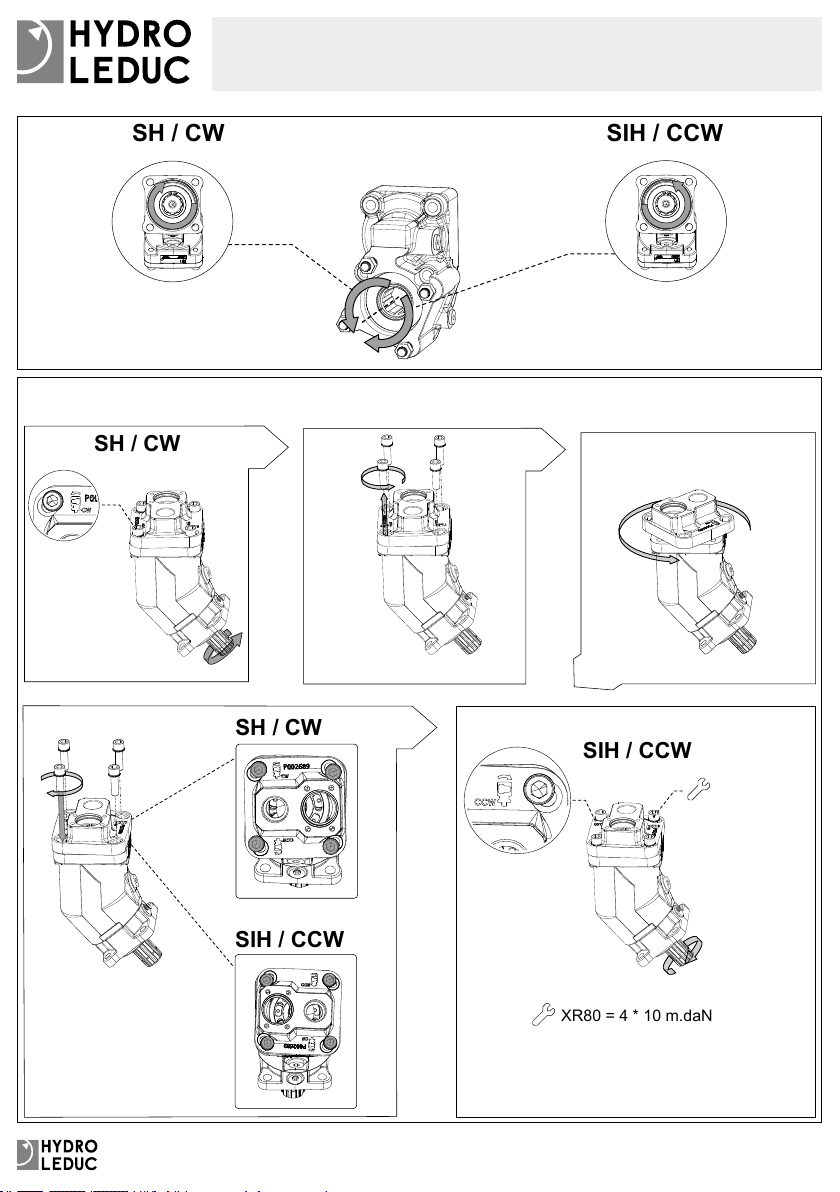
5 - MONTAGE PIPE ASPIRATION
Monter la pipe d’aspiration suivant le
schéma à droite (pour le choix de la
pipe voir page 8). Huiler le joint torique
dans la culasse, et vérier qu’il n’est pas
abîmé.
Serrer l’ensemble avec les 4 vis de
xation.
5 - ASSEMBLY OF INLET FITTING
Position the inlet tting according to
the diagram on the right (for inlet tting
selection, see page 8). Lubricate the
O-ring in the back cover and check it is
not damaged. Tighten the four screws.
5 - EINFÜHRUNG MONTAGE
Positionieren Sie den Einlassstutzen
entsprechend dem Diagramm rechts
(Auswahl des Einlassstutzens siehe
Seite 8). Den O-Ring in der Rückplatte
schmieren und prüfen, dass er nicht
beschädigt ist. Ziehen Sie die vier
Schrauben fest.
BP 9 - F 54122 Azerailles - France - Tel : (33) 03.83.76.77.40 - Fax : (33) 03.83.75.21.58 - www.hydroleduc.com - [email protected]
5
4.2
4 m.daN
GREASE
3 4.1
4 * 2.5 m.daN
5
BP 9 - F 54122 Azerailles - France - Tel : (33) 03.83.76.77.40 - Fax : (33) 03.83.75.21.58 - www.hydroleduc.com - [email protected]
6
FR EN DE
6 - MISE EN HUILE
S’assurer de la parfaite propreté du
réservoir, de la conduite d’alimentation
et de l’étanchéité de cette dernière.
Brancher les conduites d’alimentation et
de refoulement.
Ensuite ouvrir la vanne d’isolement du
réservoir (si elle existe) et faire le plein
du réservoir, si possible avec un groupe
de remplissage équipé d’un ltre. La
propreté de l’huile doit être suivant nos
recommandations : 20/18/15 suivant
ISO 4406.
6 - OIL SUPPLY
Make sure that the hydraulic reservoir
and suction line are clean and that the
suction line is correctly sealed.
Connect the suction lines and pressure
line to the pump.
Then open the tank isolation valve
(if there is one) and ll in the hydraulic
tank with a lling device including a
lter. The preferably cleanliness of the
hydraulic oil has to be according to our
recommendation: 20/18/15 according to
ISO 4406.
6 - ANSCHLUSS DER SAUGLEITUNG
Stellen Sie sicher, dass der
Hydrauliktank und die Saugleitung
sauber sind und dass die Saugleitung
korrekt abgedichtet ist.
Schließen Sie die Saugleitung und die
Druckleitung an die Pumpe an.
Ö󰀨nen Sie dann das Tankabsperrventil
(falls vorhanden). Beim Befüllen des
Hydrauliktanks mit Öl empfehlen wir
dies über einen Filter auszuführen. Die
für den Betrieb der Pumpe benötigte
Ölreinheitsklasse nach ISO 4406 ist die
Klasse 20/18/15.
7 - MISE EN ROUTE ET PURGE
Faire fonctionner la pompe à basse
vitesse, jusqu’à ce que la pompe soit
complétement purgée en air.
7 - COMMISSIONING
AND PRIMING
Start-up the pump at low speed, until
the pump is completely lled and no air
remains.
7 - INBETRIEBNAHME UND
ENTLÜFTEN
Starten Sie die Pumpe mit niedriger
Geschwindigkeit, bis die Pumpe
vollständig entlüftet und mit Öl gefüllt ist.
8 - CONTRÔLE
Contrôler régulièrement que le tube
plastique n’est pas bouché et qu’il n’y
a pas d’écoulement ou de présence
d’huile dans le tube.
Dans le cas d’une fuite, stopper
immédiatement le véhicule et
vérier l’étanchéité de la pompe.
Contrôler périodiquement le serrage de
la pompe sur la prise de mouvement
conformément aux prescriptions du
fournisseur de prises de mouvement.
8 - CHECKING
Check periodically that the vent tube
is not clogged, and that there are no
leakages nor any signs of oil in the tube.
In case of leakage, stop the
vehicle immediately and check the
sealing of the pump.
Check the tightening of the pump-PTO
regularly, referring to the specications
given by the PTO manufacturer.
8 - KONTROLLE
Kontrollieren Sie regelmäßig, dass der
Indikatorschlauch am Pumpenansch
nicht verstopft ist und sich hierin keine
Leckagen oder Ölspuren zeigen.
Im Falle einer Leckage sofort
das Fahrzeug anhalten und die
Abdichtung der Pumpe prüfen.
Wir empfehlen, die Befestigung der
Pumpe am Nebentrieb regelmäßig
zu überprüfen, wobei auf die vom
Nebenantriebshersteller angegebenen
Spezikationen verwiesen wird.
INSTRUCTION DE MISE EN ROUTE | START-UP PROCEDURE | ANWEISUNG
BP 9 - F 54122 Azerailles - France - Tel : (33) 03.83.76.77.40 - Fax : (33) 03.83.75.21.58 - www.hydroleduc.com - [email protected]
7
INSTRUCTION DE MISE EN ROUTE | START-UP PROCEDURE | ANWEISUNG
Mini : -0.2 bar
Maxi : 2 bar
6 - 7
8
BP 9 - F 54122 Azerailles - France - Tel : (33) 03.83.76.77.40 - Fax : (33) 03.83.75.21.58 - www.hydroleduc.com - [email protected]
8
FR EN DE
9 - CHOIX DU RACCORD
D’ASPIRATION
Le raccord d’aspiration doit être
choisi en fonction de l’installation.
Nous recommandons une vitesse
d’écoulement du uide entre 0,5
et 0,8m/s.
9 - CHOICE OF INLET FITTING
The inlet tting has to be
dimensioned as a function of the
installation and we recommend to
ensure a ow speed between 0.5
and 0.8m/s.
9 - WAHL DER
SAUGSTUTZENGRÖSSE
Der Saugstutzen muss
in Abhängigkeit des
maximalen Volumenstroms
dimensioniert werden, um eine
Fließgeschwindigkeit zwischen 0,5
und 0,8 m / s nicht zu überschreiten.
10 - HUILE HYDRAULIQUE
Nous recommandons l’utilisation
d’huile hydraulique minérale
de type HLVP suivant la norme
DIN 51524-2 ou HV suivant la
norme ISO11158. Les uides
biodégradables de type HEES
suivant ISO15380 peuvent être
utilisés. La viscosité de ces uides
devra être comprise entre 15 et
400 cSt. La viscosité optimum sera
entre 20 et 40 cSt.
Une viscosité de 1000 cSt
maximum est tolérée pour un
démarrage à basse vitesse et sans
pression.
La température du uide dans la
pompe ne doit pas excéder 80°C.
10 - HYDRAULIC OIL
We recommend using a mineral
hydraulic oil of type HLVP
according to DIN 51524-2 or HV
according to ISO 11158.
Bio hydraulic oils HEES according
to ISO 15380 can be used.
The recommended viscosity of the
uids is between 15 and 400 cSt.
The optimum viscosity is between
20 and 40 cSt.
A viscosity of maximum 1000 cSt is
tolerated for start-up at low speed
and without load.
The temperature of the uid should
not exceed 80°C.
10 - HYDRAULIKÖL
Wir empfehlen ein Mineral
Hydrauliköl vom Typ HLVP nach
DIN 51524-2 oder HV nach ISO
11158 zu verwenden.
Die Bio-Hydrauliköle HEES nach
ISO 15380 können ebenfalls
verwendet werden.
Die empfohlene Viskosität der
Flüssigkeit liegt bei 15 bis 400 cSt.
Die optimale Viskosität liegt bei
20 bis 40 cSt.
Eine Viskosität von maximal
1000 cSt wird bei Inbetriebnahme
der Pumpe und bei niedriger
Drehzahl und ohne Belastung
toleriert. Die Temperatur des
Hydrauliköls sollte 80°C nicht
überschreiten.
11 - FILTRATION
La propreté de l’huile pour ce
type de pompe est de minimum
20/18/15 suivant ISO 4406 (ou
classe 9 suivant NAS 1638).
11 - FILTRATION
Oil cleanliness for this type of pump
is minimum 20/18/15 according to
ISO 4406 (or class 9 according to
NAS 1638).
11 - FILTRIERUNG
Die Ölreinheit des Hydrauliköls
hat der Klasse 20/18/15 nach
ISO 4406 (oder Klasse 9 gemäß
NAS 1638) zu entsprechen.
12 - STOCKAGE
La pompe peut être stockée
maximum 1 an dans son emballage
d’origine et dans un endroit sec.
Ne pas exposer le produit à des
températures excédant -30 °C et
80°C.
12- STORAGE
The pump can be stored for
maximum 1 year in its original
packing, and in a dry area. Do not
expose the product to temperatures
below -30 °C and above 80°C.
12 - LAGERUNG
Die Pumpe darf maximal 1 Jahr in
Originalverpackung und in trock-
ener Umgebung gelagert werden.
Setzen Sie die Pumpe hierbei
keinen Temperaturen unter -30 ° C
und über 80 ° C aus.
PRECONISATION D’UTILISATION | USING RECOMMENDATION
EMPFEHLUNG FÜR DIE VERWENDUNG
BP 9 - F 54122 Azerailles - France - Tel : (33) 03.83.76.77.40 - Fax : (33) 03.83.75.21.58 - www.hydroleduc.com - [email protected]
9
Visco. (cSt)
Temp.°C
-30-40 -20 -10 02010 30 40 50 60 70 80 90 100 110 120 130 140
3.0
4
5
6
7
8
9
10
20
1000
10000
µ= f(T)
Optimum
Recommended
Max. for cold start
Max. Oil Temp.
40
400
15
20/18/15
PRECONISATION D’UTILISATION | USING RECOMMENDATION
EMPFEHLUNG FÜR DIE VERWENDUNG
Ø D Q Max*.
1½" (39.1 mm) 60 l/min
2" (50 mm) 120 l/min
2½" (63.5 mm) 150 l/min
* Qmax. recommandé/Qmax. recommended / Qmax. Empfohlen
9
Ø D
Q
10
11
BP 9 - F 54122 Azerailles - France - Tel : (33) 03.83.76.77.40 - Fax : (33) 03.83.75.21.58 - www.hydroleduc.com - [email protected]
NOTES
BP 9 - F 54122 Azerailles - France - Tel : (33) 03.83.76.77.40 - Fax : (33) 03.83.75.21.58 - www.hydroleduc.com - [email protected]
NOTES
BP 9 - F 54122 Azerailles - France - Tel : (33) 03.83.76.77.40 - Fax : (33) 03.83.75.21.58 - www.hydroleduc.com - [email protected]
HYDRO LEDUC SAS
Siège social & Usine
Head Offi ce and Factory
BP 9
F-54122 AZERAILLES
FRANCE
Tel. +33 (0)3 83 76 77 40
Fax +33 (0)3 83 75 21 58
HYDRO LEDUC GmbH
Am Ziegelplatz 20
D-77746 SCHUTTERWALD
DEUTSCHLAND
Tel. +49 (0) 781-9482590
Fax + 49 (0) 781-9482592
HYDRO LEDUC AB
Betongvägen 11
461 38 TROLLHÄTTAN
SWEDEN
Tel. + 46 (0) 520 10 820
HYDRO LEDUC BV
Ericssonstraat 2
5121 ML RIJEN
THE NETHERLANDS
Tel. +31 161 747816
HYDRO LEDUC N.A. Inc.
Grand Parkway Industrial Park
23549 Clay Road
KATY, TX 77493
USA
Tel. +1 281 679 9654
HC-ja_20210118

Other Hydro Leduc Water Pump manuals

Hydro Leduc TXV Indexable User manual

Hydro Leduc

Hydro Leduc TXV Indexable User manual

Hydro Leduc XPi Installation manual

Hydro Leduc

Hydro Leduc XPi Installation manual

Popular Water Pump manuals by other brands

hp-TECHNIK UHE-WH3 Series Installation, maintenance and operation instructions

hp-TECHNIK

hp-TECHNIK UHE-WH3 Series Installation, maintenance and operation instructions

RODEX RDX8634 instruction manual

RODEX

RODEX RDX8634 instruction manual

Davey SureFlo DSF750 Installation and operating instructions

Davey

Davey SureFlo DSF750 Installation and operating instructions

Wilo DrainLift XL 2/10 Installation and operating instructions

Wilo

Wilo DrainLift XL 2/10 Installation and operating instructions

Ingersoll-Rand PD30X-X-B Operator's manual

Ingersoll-Rand

Ingersoll-Rand PD30X-X-B Operator's manual

Penguin MTD Series manual

Penguin

Penguin MTD Series manual

Flowserve CPX User instructions

Flowserve

Flowserve CPX User instructions

Pentair US instruction manual

Pentair

Pentair US instruction manual

LEYBOLD DRYVAC P Series operating instructions

LEYBOLD

LEYBOLD DRYVAC P Series operating instructions

Larzep W Series Operation manual

Larzep

Larzep W Series Operation manual

Ulvac DOP-400SB instruction manual

Ulvac

Ulvac DOP-400SB instruction manual

Xylem Bell & Gossett Domestic 616PF instruction manual

Xylem

Xylem Bell & Gossett Domestic 616PF instruction manual

Crane DEMING 3112 Series Installation, operation & maintenance manual

Crane

Crane DEMING 3112 Series Installation, operation & maintenance manual

Gemas PUMPEX-80M user manual

Gemas

Gemas PUMPEX-80M user manual

Edwards E1M5 instruction manual

Edwards

Edwards E1M5 instruction manual

Meec tools 018-291 operating instructions

Meec tools

Meec tools 018-291 operating instructions

Lowara e-NSCS Series Installation, operation and maintenance manual

Lowara

Lowara e-NSCS Series Installation, operation and maintenance manual

Zoeller 64 HD Series Repair manual

Zoeller

Zoeller 64 HD Series Repair manual

manuals.online logo
manuals.online logoBrands
  • About & Mission
  • Contact us
  • Privacy Policy
  • Terms and Conditions

Copyright 2025 Manuals.Online. All Rights Reserved.