manuals.online logo
Brands
  1. Home
  2. •
  3. Brands
  4. •
  5. HYDRO-RAIN
  6. •
  7. Accessories
  8. •
  9. HYDRO-RAIN HRC-100-RS-HW User manual

HYDRO-RAIN HRC-100-RS-HW User manual

HRC-100-RS-HW
INSTRUCTION MANUAL
Hard Wire Rain Sensor
Model 04007-24 rC
INTRODUCTION
Thank you for selecting the HRC-100-RS-HW Hydro-Rain®sensor. This sensor
will provide conservation, convenience, and flexibility to your fully automatic
watering system. Never again will you see your sprinklers running on a rainy
day. After a set amount of rain has fallen the sensor engages a switch that
will prevent the timer from watering. Once the rain sensor has dried
sufficiently or the temperature rises above 37˚F (3˚C), the sensor allows
normal sprinkler operation.
INSTALLATION INSTRUCTIONS
Mounting
The HRC-100-RS-HW sensor includes 2 mounting options.
1. ½" Threaded Adapter
2. Rain Gutter or flat surface adapter
Mount the sensor where it will be exposed to direct, unobstructed rainfall
(but away from sprinkler spray). The switch-housing portion must be upright
(see Figure 1).
Hints for mounting:
A. Mount as close as possible to the timer. This will cause the wire run to be
shorter, which minimizes the possibility of wire breaks.
B. Mount in the highest possible position where rain can fall directly upon the
sensor.
C. As described in the “Operation” section of this manual, “reset rate” refers to
the amount of time it takes the sensor to dry out sufficiently for the sprinkler
system to be allowed to come back on. The mounting location will affect this
rate and should be taken into consideration should extreme conditions exist.
For example, mounting the sensor on a very sunny, southeastern end of
a building may cause the sensor to dry out sooner than desired. Similarly,
mounting on the northern end of a building with constant shade may keep the
sensor from drying soon enough. Some experimentation and use of the “vent
ring” (as described later) will usually yield satisfactory results.
Once the sensor is mounted, run the wire to the controller, using wire clips
every few feet to fasten it. If an extension to the wire provided is needed, use the
following table to determine the minimum wire gauge needed:
Wiring
Important: The sensor is sold and designed for 24-Volt irrigation controllers
only. All wiring must conform to applicable local codes.
The two most common wiring situations are detailed below. For non-standard
wiring situations, please consult your distributor.
A. 24-Volt Solenoid Valves Only (No booster pump) (See Figure 2) With the two
wires from the sensor at the controller, locate the “common ground” wire
of the solenoid valves. If it is connected to the common terminal on the
controller disconnect it. Attach one wire of the sensor to the “common”
terminal (usually marked “COM”) on the controller. Attach the other wire of
the sensor to the common wire leading to the valves. Note: The common wire
to the valves does not have to be interrupted at the controller. The sensor
may be wired anywhere along the common wire line.
B. 24-Volt Solenoid Valves with booster pump (See Figure 3). Locate the
common wire to the solenoid valves and the common wire lead to the coil
of the relay that starts the pump. If these two wires are connected to the
“common” terminal on the controller, disconnect both of them. Twist these
two wires together along with one wire from the sensor and secure with a
wire nut. Attach the other wire of the sensor to the “common” terminal on the
controller. Note: The pump circuit output must be 24 volts in this situation if
different do not proceed.
25-50 ft. 50-100 ft. 100 ft. or more
20 AWG 18 AWG 16 AWG
Extension needed:
then use:
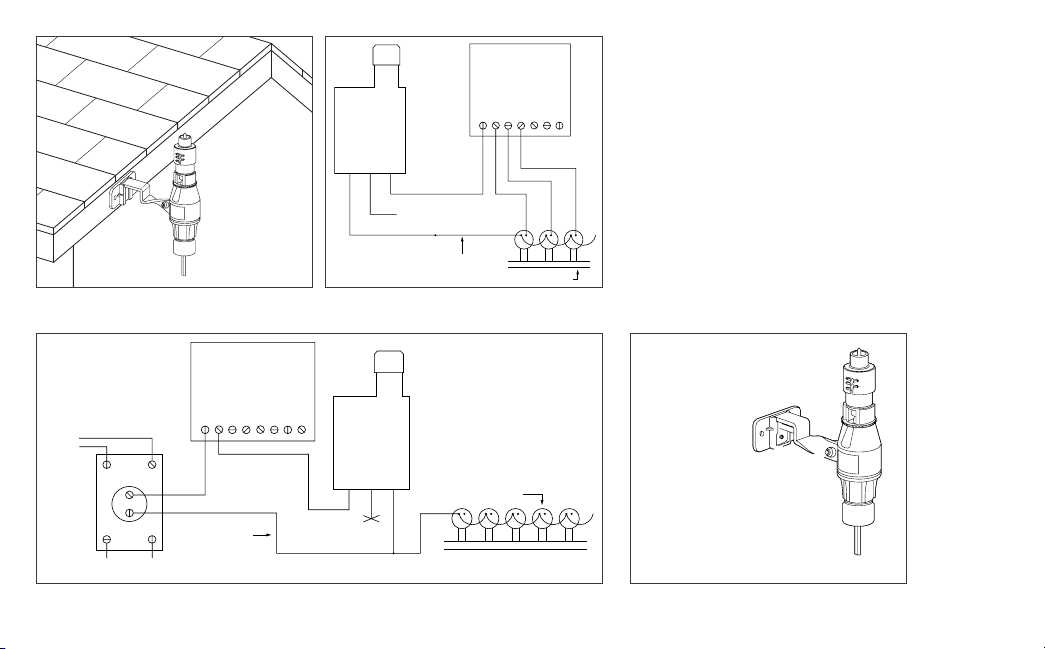
OPERATION CHECK TO VERIFY CORRECT WIRING
Turn on one zone of the sprinkler system that is visible while you are in reach
of the sensor. Manually depress the spindle at the top of the sensor until you
hear the switch “click” off. The sprinkler zone should stop instantly. If it does
not, check wiring for correct installation.
ADJUSTMENTS AND OPERATION
The sensor can keep the irrigation system from starting or continuing after
rainfall quantities of ¹⁄8", ¼", ½", ¾", or 1". To adjust to the desired quantity of
rainfall, rotate the cap on the switch housing so that the pins are located in the
proper slots (See Figure 4). Do not forcibly twist the cap as this might break the
pins. The time that it takes the sensor to reset for normal sprinkler operation
after the rain has stopped is determined by weather conditions (wind, sunlight,
humidity, etc.). These conditions will determine how fast the hygroscopic discs
dry out, and since the landscape is also experiencing the same conditions, their
respective drying rates will roughly parallel each other. There is an adjustment
capability on the sensor that will slow down the reset rate. By turning the “vent
ring” (See Figure 4) to completely or partially cover the ventilation holes, the
hygroscopic discs will dry more slowly. This adjustment can compensate for an
“overly sunny” installation location or peculiar soil conditions. Experimenting
with the vent rings will best determine the ideal vent setting.
BYPASSING THE SENSOR
Should you desire to bypass the operation of the sensor for any reason
(i.e., turn on your system even though the sensor has shut “off” due to rainfall
or temperature), there is an easy way to do this. Simply go to the sensor and
raise the rain quantity “cap” setting higher, or completely remove it altogether.
This takes the pressure off the switch button, which allows the valve circuit to
close again. Note: Using the “manual” switch on the controller will not bypass
the sensor.
MAINTENANCE
There is no required maintenance for the unit. The sensor does not have to be
removed or covered for winterizing purposes. All parts are easily replaceable if
they become damaged or lost. The spindle assembly is designed to stay with the
cap. Do not pull them apart. (See Figure 4)
TROUBLESHOOTING
Follow these simple checks before replacing your sensor:
System will not come on at all:
A. Check to see that the sensor discs are dry and the switch “clicks” on and off
freely by pressing the top of the spindle.
B. Look for breaks in the wire leading to the sensor and check all wire junctions.
C. If the sensor is dry, the temperature is above 37°F ±2° (3°C ±1°) and the wire
leading to it is good, check the sensor switch by nicking the insulation of the
two “outer” wires near the unit to expose copper. Turn one sprinkler zone on,
and apply a “jumper wire” across the two exposed wires. If the sprinkler now
comes on, the switch is bad. Wrap all nicked wires with electrical tape.
D. The sensor is wired to function with most controllers. If you are unable to
make the sensor work with the suggestions above you may have a unique
controller. In this case you will need to cut the copper colored wire and attach
it to the blue lead wire provided.
System will not shut off even after heavy rainfall:
A. Check wiring for correct installation. (See “Operation Check to Verify
Correct Wiring”.)
B. Check sensitivity setting on sensor, and move the cap to a more
sensitive setting. The sensor is an accurate rain gauge and can be
verified by setting up a “tube” type rain gauge in the same vicinity and
making periodic readings.
C. Check for obstructions to rainfall such as overhangs, trees or walls.
WARRANTY
Hydro-Rain®warrants to its customers that its HRC-100-
RS-HW product will be free from defects in materials and
workmanship for a period of three years from the date of
purchase. We will replace, free of charge, the defective part or
parts found to be defective under normal use and service for a
period of up to three years after purchase (proof of purchase
required). We reserve the right to inspect the defective part
prior to replacement. Hydro-Rain®will not be responsible for
consequential or incidental cost or damage caused by the
product failure. Hydro-Rain®liability under this warranty is
limited solely to the replacement or repair of defective parts.
To exercise your warranty, return the unit to your dealer with
a copy of the sales receipt.
The microswitch is UL-approved for electrical safety.
C123456
Timer - Controller
Common Wire
to all Valves
HRC-100-RS-HW
Third Normally-Open Lead
Solenoid Valves
C
Pump
or
MV 123456
Timer - Controller
HRC-100-RS-HW
Terminate
Line-In
Line-Out
(to Pump)
Common Wire
to All Valves
Solenoid Valves
Normally-
Open Relay
Figure 3: Wiring
Figure 2: WiringFigure 1: Mounting Rain Sensor
Figure 4: Parts Diagram
ACap
BSpindle Assembly
CVent Ring
DVent Ports
EHousing
FLocknut and
Screw Assembly
GMounting Bracket
HThumbscrew
ISlip and Threaded Mount
J24 VAC Wire to Controller
A
B
C
D
E
J
G
I
F
H
915 Overland Street, North Salt Lake, UT 84054 1.888.HYDRORAIN www.hydrorain.com
HELP: Before returning this sprinkler controller to the store,
contact Hydro-Rain®Technical Service at-1-888-HYDRORAIN

Other HYDRO-RAIN Accessories manuals

HYDRO-RAIN HRC-990-RS-MD User manual

HYDRO-RAIN

HYDRO-RAIN HRC-990-RS-MD User manual

HYDRO-RAIN HRC-100-RS-RF User manual

HYDRO-RAIN

HYDRO-RAIN HRC-100-RS-RF User manual

Popular Accessories manuals by other brands

Vega VEGAPULS 66 operating instructions

Vega

Vega VEGAPULS 66 operating instructions

camry Premium CR7418 user manual

camry

camry Premium CR7418 user manual

Apogee Instruments SQ-620-SS owner's manual

Apogee Instruments

Apogee Instruments SQ-620-SS owner's manual

Omron E3X-N manual

Omron

Omron E3X-N manual

Stahl SolConeX 8573/13 Series operating instructions

Stahl

Stahl SolConeX 8573/13 Series operating instructions

Schwaiger SDPIR100 user guide

Schwaiger

Schwaiger SDPIR100 user guide

Trotec BX09 operating manual

Trotec

Trotec BX09 operating manual

Hytronik HMW14 Installation and instruction manual

Hytronik

Hytronik HMW14 Installation and instruction manual

Lightolier Lytespan 8102 specification

Lightolier

Lightolier Lytespan 8102 specification

APG LPU-2127 user manual

APG

APG LPU-2127 user manual

ASCOM I75 datasheet

ASCOM

ASCOM I75 datasheet

Graco 257823 quick start guide

Graco

Graco 257823 quick start guide

Inxpect MSK-101 Advanced configuration manual

Inxpect

Inxpect MSK-101 Advanced configuration manual

MTS Systems Temposonics R-Series Operation manual

MTS Systems

MTS Systems Temposonics R-Series Operation manual

Huawei Airbridge DBS3900 Product description

Huawei

Huawei Airbridge DBS3900 Product description

Beacon Athletics TUFFScreen Pitcher's L Assembly guide

Beacon Athletics

Beacon Athletics TUFFScreen Pitcher's L Assembly guide

Avid Technology HD MADI Guide

Avid Technology

Avid Technology HD MADI Guide

Avery Weigh-Tronix 1310 user manual

Avery Weigh-Tronix

Avery Weigh-Tronix 1310 user manual

manuals.online logo
manuals.online logoBrands
  • About & Mission
  • Contact us
  • Privacy Policy
  • Terms and Conditions

Copyright 2025 Manuals.Online. All Rights Reserved.