U.L. LISTED – Hydromassage Bathtubs
IAPMO LISTED – Uniform Plumbing Code
U.L. LISTED – Pumps
IAPMO LISTED –
Uniform Swimming Pool, Spa & Hot Tub Code
HYDRO SYSTEMS, INC., 29132 Avenue Paine, Valencia, CA 91355 | 661-775-0686 | Fax: 661-775-0668
1) Any items manufactured by other companies and installed by HYDRO SYSTEMS, INC. Such items may carry
warranties offered by the manufacturer of the original items.
2) Problems resulting from failure to comply with installation instructions or drawings, or improper installation.
3) Problems resulting from abuse, misuse, negligence or accident by any party other than HYDRO SYSTEMS, INC.
such as, but not limited to, damage to parts by installers.
4) Problems resulting in whole or part from alteration or modification of these products by any party.
5) Metal failures due to chemical corrosion.
This warranty is provided to you as part of your purchase order. It gives you specific legal rights. You should keep
it in a safe place along with your purchase order.
U
T
L
L
I
S
E
D
2
1
2
5
UL
L
I
S
T
E
D
5
9
7
9
8
This limited warranty is extended to the first user or the original retail purchaser for a period of ten (10) years on the
bathtub, 5 years on electronics and 2 years on the air channel, plumbing, and labor to replace electronics or any other
repair that is covered from date of purchase, and is not enforceable by any other party. HYDRO SYSTEMS, INC.
warrants that the system and/or bathtub is free from defects in the workmanship and/or materials.
This limited warranty does not include any other items not manufactured by HYDRO SYSTEMS, INC. HYDRO
SYSTEMS, INC. does not assume liability for the finish or the wearing quality of any plated product. No dealer or other
person has any authority to make any warranties or representations concerning HYDRO SYSTEMS, INC. or its products.
Accordingly, HYDRO SYSTEMS, INC. is not responsible for any such warranties or representations. THERE ARE NO
WARRANTIES BEYOND THE DESCRIPTION ON THE FACE HEREOF. NO WARRANTY OF MECHANTABILITY,
FITNESS, NOR OTHER WARRANTY (WHETHER EXPRESS, IMPLIED OR STATUTORY) IS MADE BY HYDRO SYSTEMS,
INC., EXCEPT THAT IT WARRANTS THE GOODS TO BE FREE FROM DEFECTS IN MATERIALS AND WORKMANSHIP
IN NORMAL USE AND SERVICE AS DESCRIBED ON THE FACE HEREOF.
WARRANTY OBLIGATIONS OF HYDRO SYSTEMS, INC.:
Should a defect in workmanship and/or material in any item covered by this warranty become evident during the term
of the warranty, then upon the consumer following the procedures set forth below, HYDRO SYSTEMS, INC. at its
opinion, will repair or replace such item at its own cost and expense. HYDRO SYSTEMS, INC. is not, however, responsible
under this warranty for any cost of shipping or transportation or the equipment or parts thereof to or from the Service
Department. Also, HYDRO SYSTEMS, INC. is not liable for any loss of time, inconvenience, incidental expenses such as
telephone calls, labor or material charges incurred in connection with the removal or the replacement of the
equipment, or any other incidental or consequential damages, unless otherwise prohibited by applicable State law.
PROCEDURES TO BE FOLLOWED TO OBTAIN WARRANTY SERVICE:
Upon discovery of any defect or malfunction, notify the supplier/installer and HYDRO SYSTEMS, INC. Service
Department, 29132 Avenue Paine, Valencia, CA 91355, telephone: (661) 775-0686, within (10) ten days and include a
description of the malfunction or defect, the Hydro Systems distributor's name and purchase order number or the
5-digit bathtub serial number. The bathtub serial number can be found on the warranty card or on the model card
located on the underside of the bathtub.
1) Upon inspection, HYDRO SYSTEMS, INC. at its option will repair or replace any defective or malfunctioning part of
its system or bathtub. If repairs cannot be made on site, HYDRO SYSTEMS, INC. at its opinion will repair or replace at
the factory. However, the cost of removal or installation of a replacement system and cost of transportation to and
from HYDRO SYSTEMS, INC. are not covered. All parts, labor and materials necessary to repair the system or bathtub
are covered except parts excluded below.
EXCLUSIONS – THIS WARRANTY DOES NOT COVER:
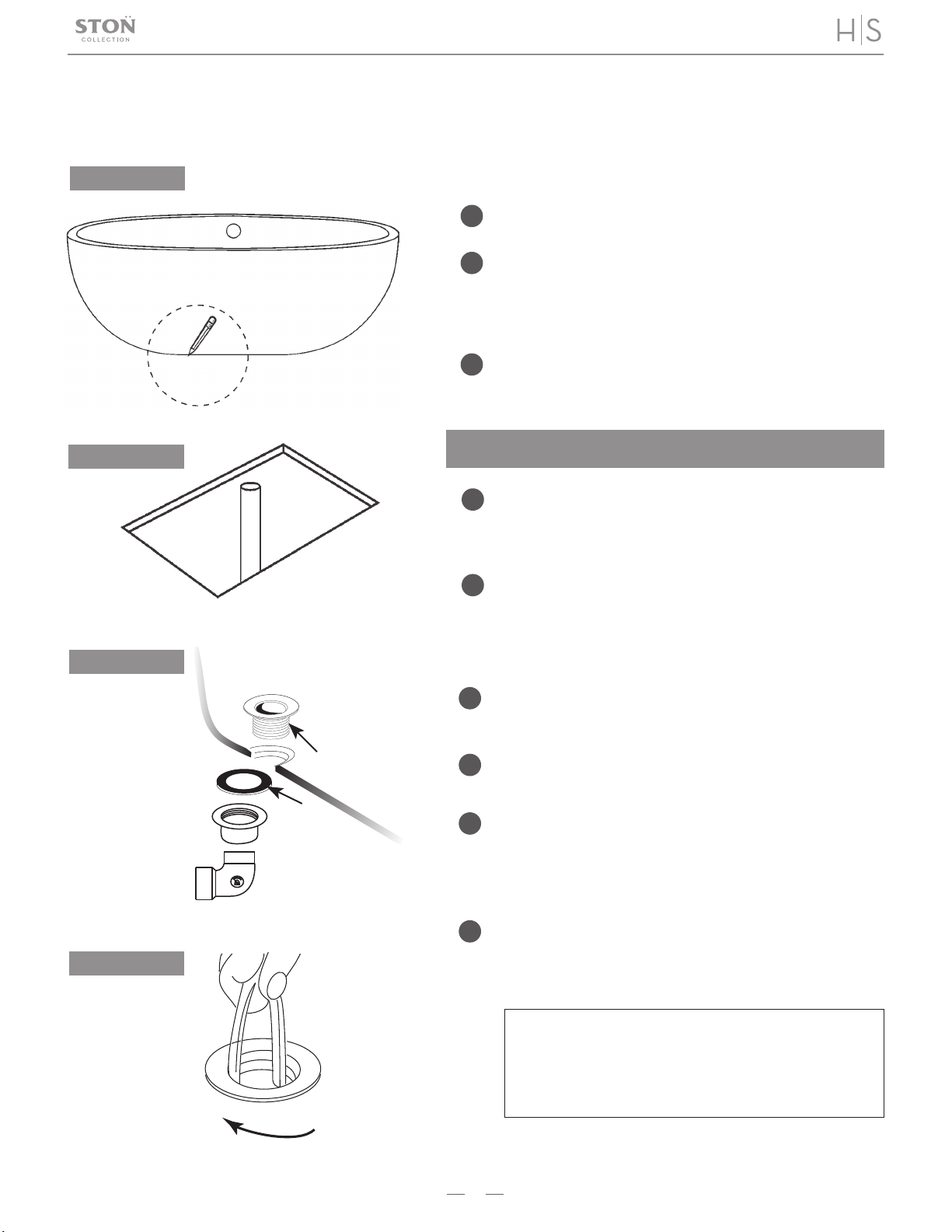
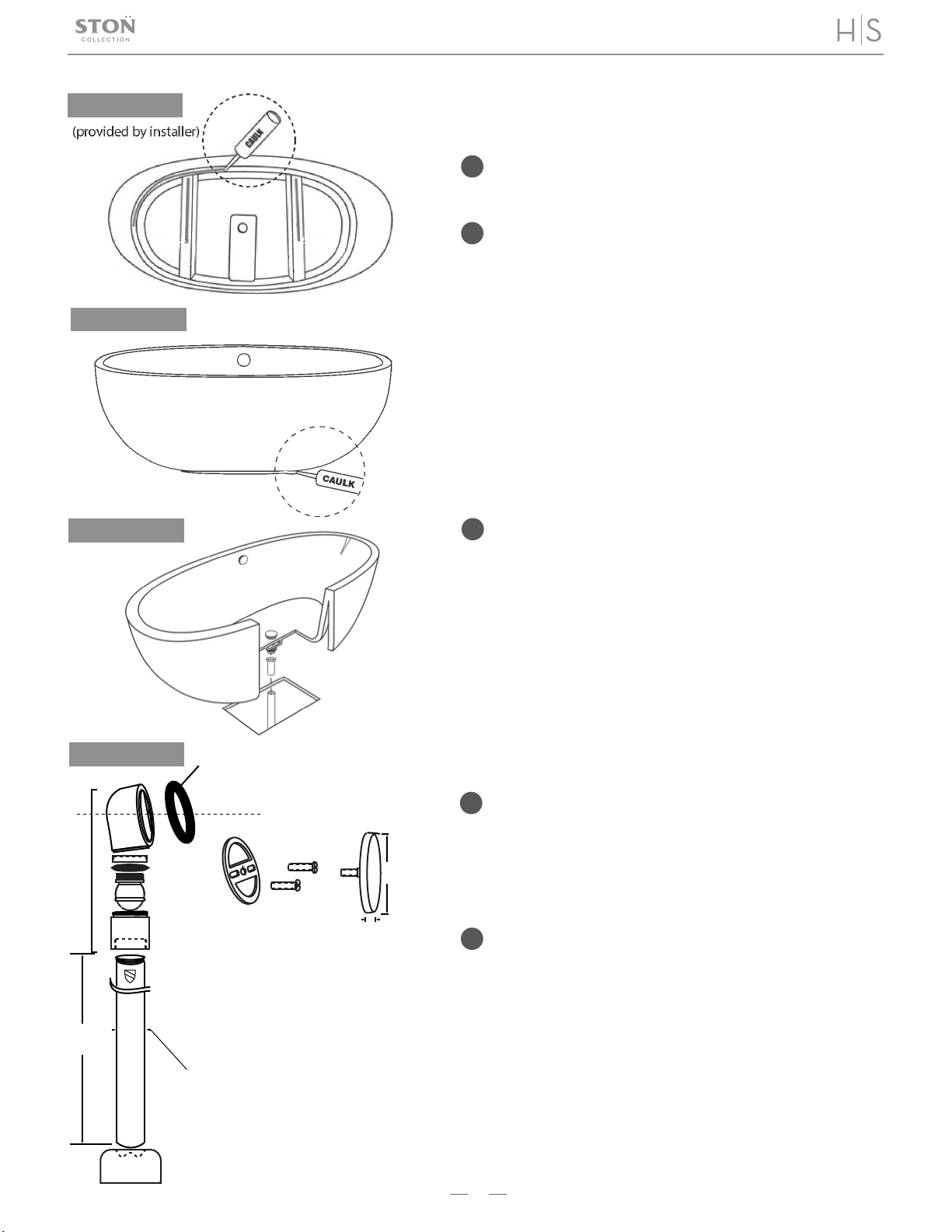
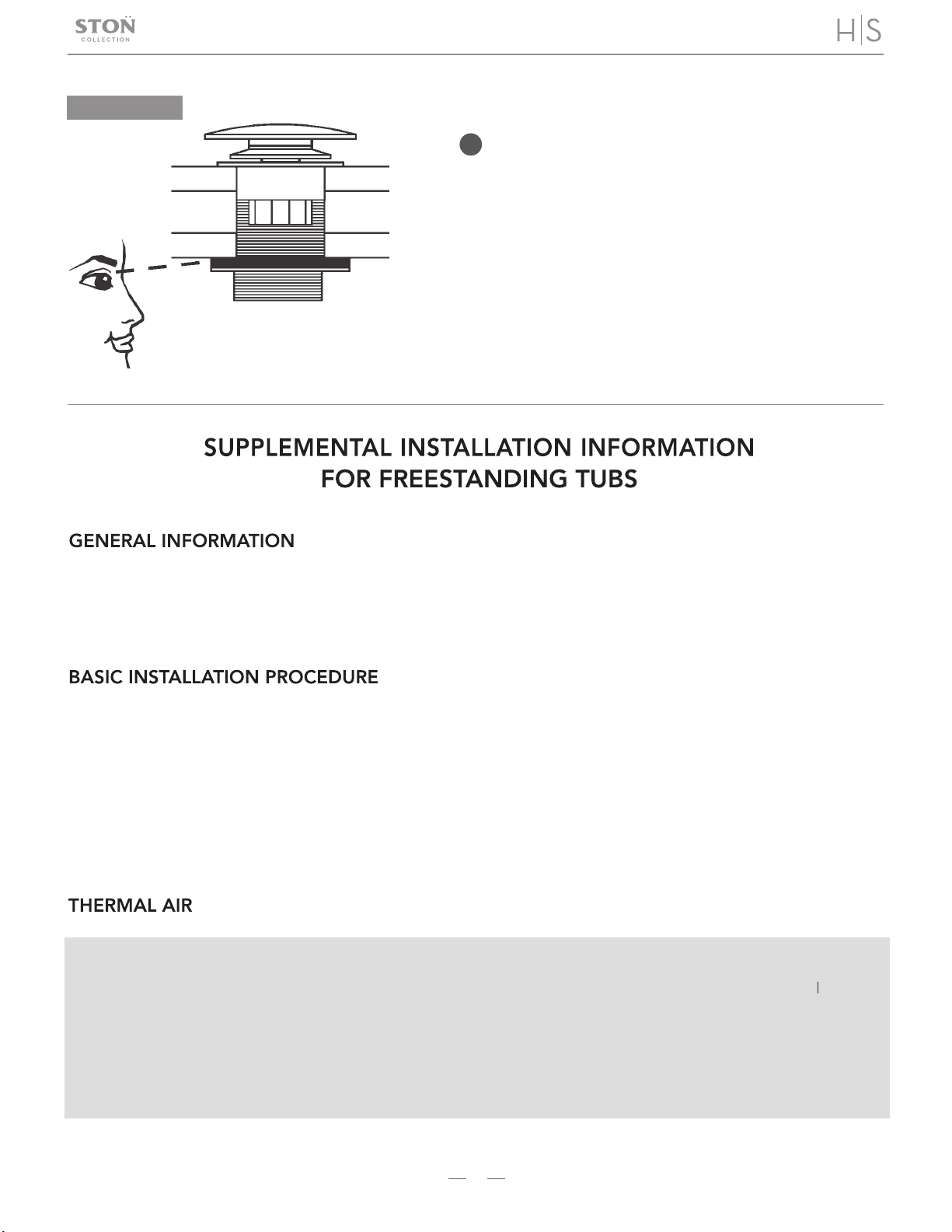
INSTALLATION INSTRUCTIONS