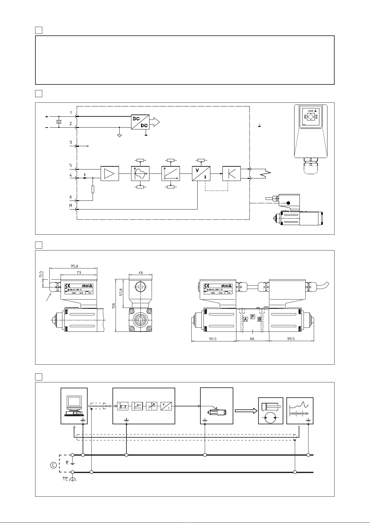
4.1 Power supply and wiring
The power supply must be appropriately stabilized or rectified and filtered. If the power supply is
generated by a single phase rectifier use a 10000 µF/40V capacitor; if pulse voltage is generated
by a three phase rectifier, connect a 4700 µF/40V capacitor (see ).
Connect the reference signal to the main electronic control by means of shielded and twisted
cables. Pay attention: the negative and the positive poles must not be exchanged each other.
Shield the wirings to avoid electromagnetic noise (EMC).
It is suitable to keep the driver and its cables far from any electromagnetic radiation source (like
cables where high currents flow, electric motors, transformers, relays, solenoids, portable radio-
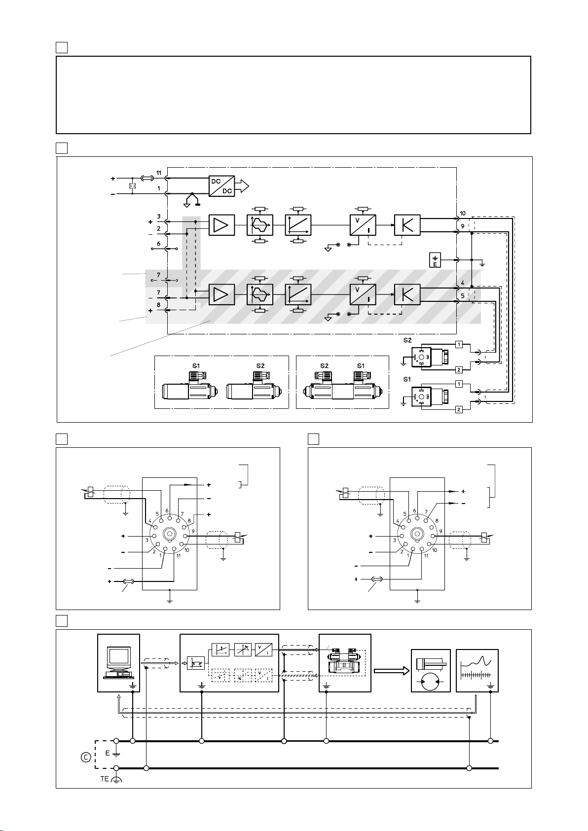
transmitter, etc.). Wire the earth connection as shown in , according to CEI EN 60204-1 stan-
dards. Connect the shield of the driver to the noiseless earth terminal (TE) .
The driver is designed to correc-
tly work with 24 VDC (±20%) or 12
VDC (±20%) nominal voltage sup-
ply coupled with coils having a
resistance from 2,0 Ωto 13,4 Ω,
as shown in the side table.
4.2 Reference signal
The electronic driver is designed
to receive a voltage reference signal according to the following options:
– potentiometers mounted externally and wired according to the application diagrams, see .
– external reference signals generated by PLC, see and .
4.3 onitor signal
This voltage output signal allows to measure the current supplied to the coil, read by a voltmeter
on the front panel test points (see ). Reading scale is 1 mV = 1 mA.
To visualize the signals use voltmeters with impedance >10 K
Ω
.
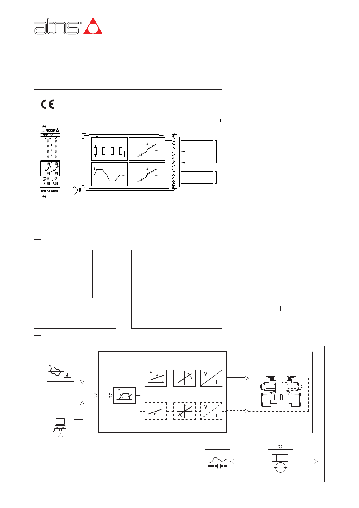
4.4 Set code
Basic calibration of the electronic driver is factory pre-set, according to the proportional valve it
has to be coupled with. These pre-calibrations are identified by a standard number in the model
code as follows:
1 = RZGO, KZGO 3 = DHZO, DKZOR 4 = DPZO-A-*5, DPZO-A-*7
2 = RZMO, AG*ZO, LI*ZO 3B = DHZO-A-06, DKZOR-A-16 4B = DPZO-A-*6
6 = QV*ZO(R), LIQZO
For ex-proof valves, insert an “A” before the code of adjustment.
For example, the code of adjustment for RZGA is A1 (see table E120).
The calibrations 3B and 4B allow the coupling with single solenoid valves with two external posi-
tions.
4.5 Calibrations available to the user, see ,,,.
Scale
The relation between driving current and reference signal can be regulated with the Scale adjust-
ment.
For single solenoid valves with two external operating positions, the reference signal is ± 5V (cali-
bration codes 3B and 4B).
Separate Scale potentiometers P3 and P4 for solenoids S1 and S2 enable the electronic card to be
set for different output currents, obtaining differential hydraulic operations.
Bias (dead band)
Regulation of dead band adjusts the hydraulic zero of the valve (starting position adjustment) to a
minimum signal of 200 mV. The electronic card is factory pre-set for the valve it is coupled with,
according to the set code (see section 4.4). E-BM-AC-05F/* driver for double solenoid are equip-
ped with an internal channel selector enabling the relevant channel with input reference voltage
signal greater than ± 200 mV and supplying the bias current set by front panel Bias potentiomen-
ters P1 and P2 for each solenoid.
For drivers type E-BM-AC-01F with calibration codes 3B and 4B there is not threshold and the bias
is used for the adjustment of the central position of the valve.
Ramps see , .
The internal ramp generator circuit converts a step input signal into a slowly increasing output
signal (solenoid current). The rise/fall time of the current is set via potentiometers on front panel
up to a max. time of 10 sec. for 0-100% of reference signal.
The option /RR allows up and down dissymetrical ramps for each solenoid.
7
16
9
13
13
1514
5
11109
97
Power supply Nominal :24VDC or 12 VDC (see 4.1)
(positive on contact 11, negative on contact 1) Rectified and filtered :VRMS = 21 ÷ 33 (ripple max peak to peak = ±20%)
Max. power consumption 40 W
Imax = 3,3A type PWM square wave (with solenoid type ZO(R)-A with resistance 3,2 Ω)
Imax = 2,5A type PWM square wave (with explosion-proof solenoid with resistance 3,2 Ω)
E-BM-AC-01F R1 0 ÷+5V at contact 3 (GND on 2)
E-BM-AC-11F R1, R2 0 ÷+5V at contact 3 (GND on 2) and 0 ÷ +5V at contact 8 (GND on 7)
E-BM-AC-05F R1 ± 5V at contact 3 (GND on 2)
Reference signal variation range
(Scale adjustment)
Input signal impedence Voltage signal Ri > 10 KΩ
External potentiometers supply +5V / 10mA at contact 6 (-5V / 10mA at contact 7 only for version E-BM-AC-05F)
Ramp time 10 sec. max (0 ÷100% of reference signal)
Electrical wiring Coils : 2 x 1 mm2cable up to 20 m; 2 x 1,5 mm2shielded cable to 40 m
Box format Aluminium box DIN 43700
Connector elements available UNDECAL socket for guide DIN EN 50022-50035 type E-K-11B mounting To be ordered separately
Operating temperature -10 ÷ +60 °C (storage -20 ÷+70 °C)
Dimensions 32 x 72 x 127 mm
Weight 270 g
Rapid solenoid excitation and switching off.
Outputs to solenoids protected against accidental short circuits
3 AIN CHARACTERISTICS OF E-B -AC ELECTRONIC DRIVERS
4 GENERAL SPECIFICATIONS 5 EXTERNAL REFERENCE SIGNALS
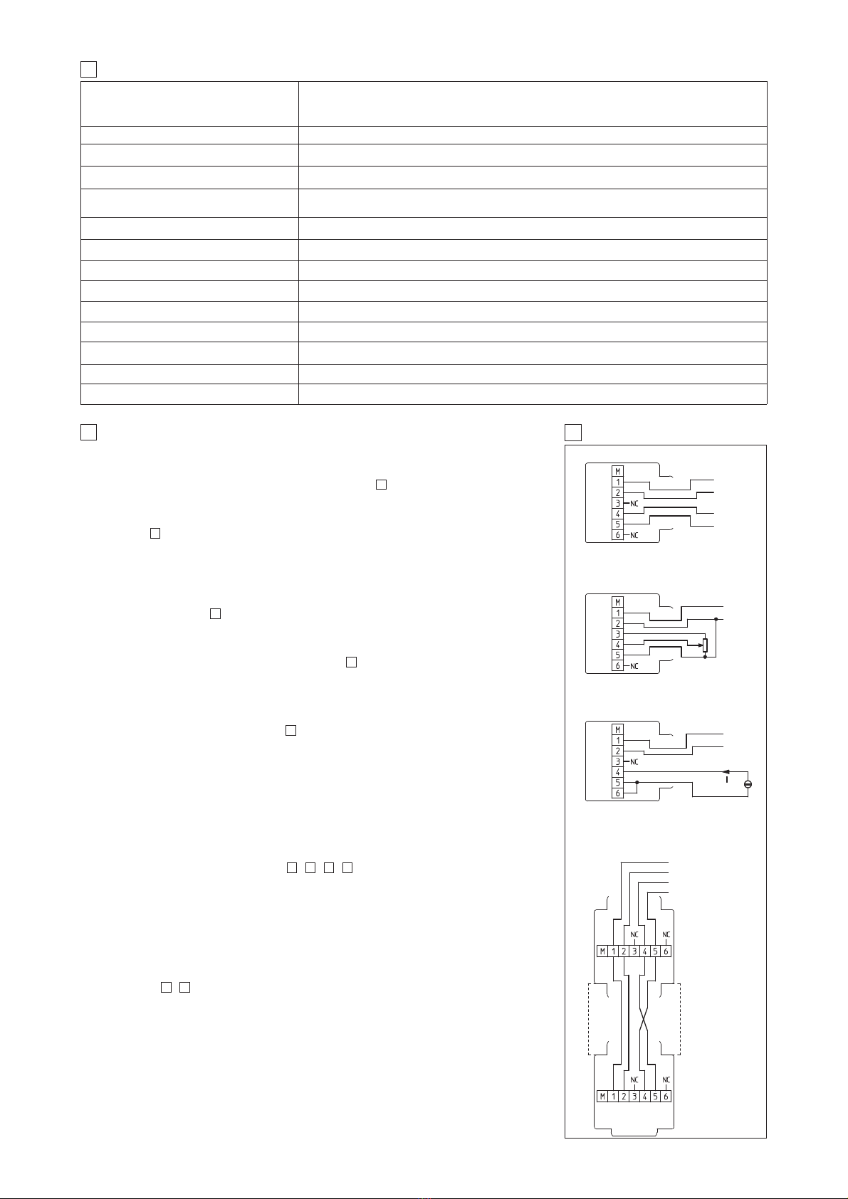
SOCKET
CONNECTIONS
EXTERNAL
POTENTIO ETER
± 10 V max ± 2,5 V min
E-B -AC-01F
E-B -AC-011F
Current supplied to solenoids
Features
Nominal reference signal, factory pre-set
E-B -AC-05F
E-B -AC-01F/3B
E-B -AC-01F/4B
Nominal supply Valve code R at 20 °C [Ω]
24 VDC
*ZMO, *ZGO, *ZO(R)-A-* (1)3,2
*ZMA, *ZGA, *ZO(R)-A-* (1)3,2
*ZMO, *ZGO, *ZO(R)-A-*/18 13,4
12 VDC *ZMO, *ZGO, *ZO(R)-A-*/6 2,1
(1) Standard coupling