HydroBikes Explorer User manual

EXPLORER
®
OWNER’S MANUAL
305 13
th
Street North
Humboldt, Iowa 50548
888-403-3012
www.hydrobikes.com
European Representative:
Doceupoint Ltd, The Old Methodist Chapel
Great Hucklow, Buxton,
Derbyshire, SK17 8RG, England
Tel +44 1298 873800
Fax +44 1298 873801
Email enquiries@doceupoint.eu

2
Table of Contents
Introduction……………………………………………………………………………………. 3
Safety Information…………………………………………………………………………...... 3-4
Features……………………………………………………………………………………….. 4-5
Assembling the EXPLORER………………………………………………………………… 5
Transporting the EXPLORER……………………………………………………………….. 14
Operating the EXPLORER…………………………………………………………………... 15
Precautions……………………………………………………………………………. 15
Adjusting the Rudder…………………………………………………………………. 15
Getting Started………………………………………………………………….......... 16
Coming Back to Shore……………………………………………………………….. 16
Steering………………………………………………………………………………… 17
Stopping………………………………………………………………………………... 17
Reversing………………………………………………………………………………. 17
Maintenance…………………………………………………………………………………… 18
Once a Day – Saltwater………………………………………………………………. 18
Once a Week During Use…………………………………………………………….. 18
Once a Year – Winterize……………………………………………………………… 18
Cleaning the EXPLORER…………………………………………………………….. 18
Repairing the EXPLORER……………………………………………………………. 18
Drive Train & Friction Lock Replacement Instructions…………………………….. 19-20
Saltwater Environment Maintenance………………………………………………… 21
Handlebar Stem Installation & Removal…………………………………………………….. 22
Specifications…………………………………………………………………………………... 23
Changing the Drive Train Lubricant………………………………………………………….. 24
Parts Description – EXPLORER I……………………………………………………………. 25
Replacement Parts & Accessory List………………………………………………………... 26
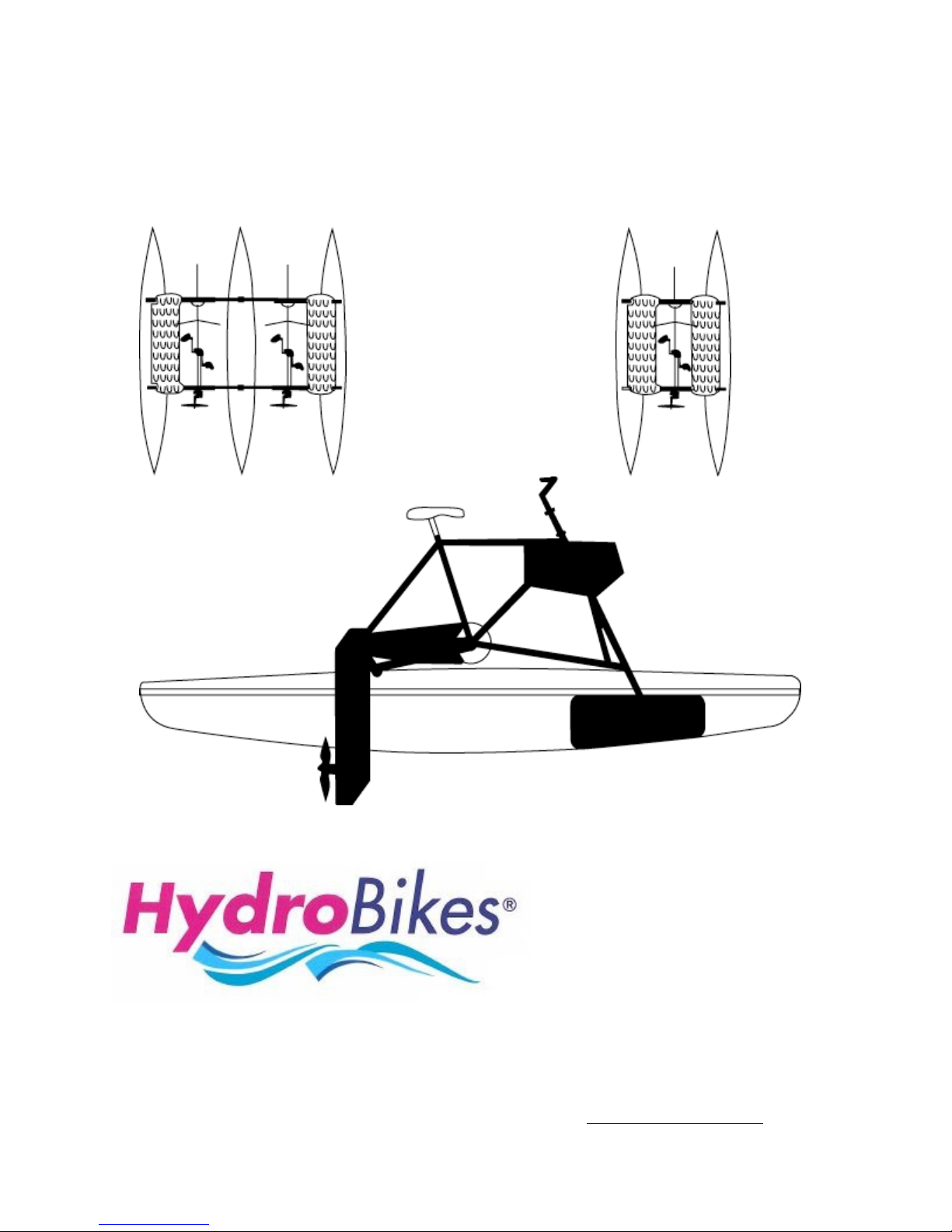
DESCRIPTION
The HydroBike EXPLORER® features an upright “traditional” bicycle frame on a pair of 10-foot
catamaran floats. This pedal-powered craft has an ultra-efficient underwater propeller capable of
pushing the craft beyond its hull speed of 6-7 mph to a sprint speed of 10 mph.
OWNER/OPERATOR RESPONSIBILITY
•
It is the owner/operators responsibility to properly use and maintain this craft.
•
The instructions and warnings contained in this manual shall be read and understood by the
owner/operator prior to operating this craft.
•
If an owner/operator does not understand English, the contents of this manual shall be
explained in the owner/operators native language to assure the owner/operator knows how to
properly operate the craft.
•
It is the owner/operator responsibility to maintain the legibility of all warning and instruction
labels.
•
The owner/operator shall retain this manual for future reference to important warnings,
operating and maintenance instructions.

3
Introduction
Thank you for purchasing the EXPLORER®! We are sure you will enjoy your new EXPLORER® for
many years to come.
Please take a few minutes to read this manual before using the EXPLORER®. Although the
EXPLORER® is simple to operate, this manual contains information about craft limitations, safety
features and maintenance obligations you must understand to enjoy the EXPLORER® to its
maximum capabilities. Information about the EXPLORER® is included in this manual that you might
not discover on your own.
If you have any questions regarding your EXPLORER® contact your local dealer.
The instructions in this manual tell you how to:
•
Assemble the EXPLORER
®
•
Transport the EXPLORER
®
•
Operate the EXPLORER
®
•
Maintain the EXPLORER
®
Then head for the lake, river or ocean, and you’re ready to ride!
Safety Information
•
Read this manual completely before assembling and operating your EXPLORER
®
•
Consult a competent medical authority prior to undertaking any exercise or fitness program
that involves the use of the EXPLORER
®
.
•
ALWAYS wear a U.S. Coast Guard approved personal floatation device (PFD) when riding on
the EXPLORER
®
.
•
The maximum load capacity of the EXPLORER® I is 400 pounds; 600 pounds for the
EXPLORER® II.
•
Do not carry passengers on your EXPLORER
®
.
•
Do not allow anyone to sit on the handlebars.
•
Do not pedal the EXPLORER® from a standing position
•
Avoid swimmers, swimming areas, and boat traffic.
•
Know and follow the boating laws and regulations of the area in which you are using the
EXPLORER
®
.

4
•
Do not operate your EXPLORER® after sunset or before dawn, unless your EXPLORER® is
equipped with lights. Please follow the laws regarding boating in the dark in the area in which
you are using the EXPLORER
®
.
•
Watch for underwater obstacles when operating the EXPLORER® in shallow water.
•
Ask about local conditions before using your EXPLORER® in unfamiliar waters.
•
Never use your EXPLORER® in stormy weather or when there is lightning. Seek shelter on
shore if a storm is coming.
•
Although the pedals are suitable for bare feet, wearing hard-bottomed footwear (sneakers or
other water footwear) is recommended.
•
Never wear loose clothing that could become entangled in any moving part of the
EXPLORER
®
.
•
Never use the EXPLORER® while under the influence of alcohol or drugs.
Features
The EXPLORER® brings bicycling to the water. Water cycling is fun, safe and easy. And like biking,
it’s a wonderful way to have fun and get exercise.
Can be used for a wide variety of water activities:
•
Sightseeing, adventure and exploration - - just like land biking
•
Fishing - - Quietly pedal to the perfect spot
•
Camping - - Takes you to where you want to go.
•
Photography - - The EXPLORER® is stable and well balanced.
•
Swimming/snorkeling - - you can climb off and back onto the floats.
•
Exercise - - Great for endurance, muscle tone and cardiovascular workout.
Comes in single (one rider) or double (two riders) models.
Moves in forward or reverse for safety and maneuverability.
Bike on lakes, rivers or even the ocean.
Faster than a paddleboat or a canoe:
•
Cruising speed…………………….5mph
•
Top Speed…………………………8-10 mph
Upright riding position provides comfort and full vision.
•
And won’t get wet!
Stable:
•
Well-balanced due to its catamaran design.
Quick and easy disassembly for storage.

5
Easy to Transport.
No harm to the environment:
•
No noise, air or water pollution.
Low Maintenance.
Computer-designed drive system delivers over 90% theoretical efficiency.
Assembling the EXPLORER
®
The frame (including the drive train, propeller, pedals, chain and chain guard) comes pre-assembled.
Some basic assemble, however, is required. The procedure for this assembly is easy and takes only
minutes.

6
Step 1: Put the seat/seat post assembly into the bike frame and tighten the quick release lever
(may come pre-assembled from factory).
Do not replace the provided seat post with an aluminum alloy seat post. This will damage the
frame.
Be sure the seat is parallel to the top of the frame.
Step 2: Put the rudder assembly into the bike frame.
•
Depress the two buttons at the top of the rudder assembly tube and slide the tube into the bike
frame, as shown, until the buttons appear and snap open again out the top of the frame.
Be careful not to pinch your fingers with the buttons.
The purpose of the buttons is to lock the rudder assembly in its UP position. See “Adjusting
the Rudder” later in this manual for a description of the two rudder positions.

7
Step 2 (continued):
•
Fit the rudder collar over the top of the rudder assembly, as shown; snug to hold in place, but
do not tighten.
•
Assemble the handlebar into the handlebar stem. Rotate the handlebar to your preference
and tighten the nut with the provided 6mm Allen Wrench.
•
Place the stem into the rudder tube. Be sure the handlebars are perpendicular to the rudder.
•
Again using the 6mm Allen Wrench, tighten the handlebar stem.

8
•
Attach the handgrips.
•
Lastly, tighten the rudder collar.
The purpose of the rudder collar is to limit the depth of the rudder’s DOWN position and
provide support so the handlebar stem does not “swell” the tube when tightened.

9
Step 3: Put the cross tubes onto the floats.
•
Attach the ends of the two cross tubes to one of the floats with two black clamping knobs, as
shown, keeping the knobs loose.
•
Align both floats the same and attach the other of the cross tubes with two black clamping
knobs.
Step 4: Put the bike frame onto the cross tubes.
•
Locate the front ends of the floats.
The front ends of the floats are inscribed with the raised warning about wearing personal
floatation devices.
IMPORTANT! Be sure the floats are position correctly. The EXPLORER® will not
provide optimum balance and stability when the floats are not oriented properly.
•
Set the bike frame on the cross tubes so
the rudder is toward the front of the floats.
Line up the holes on the bike frame with
the holes on the cross tubes, as shown.
•
If assembling with “SIDE-DECKS”,
remove both knobs from one float,
set “SIDE-DECK” on cross tubes,
and re-attach knobs.

10
Step 4 (continued):
•
For each of the four frame holes, insert a bolt through rubber washer as shown. Next insert
bolt through the bottom of the cross tube, bike frame and side deck and attach with the black
clamping knob. Hand-tighten only. Do not use a wrench to tighten the black clamping knobs.
Hand tightening is all that is necessary. Using a wrench or other tools may damage the knobs.
Note: Four rubber washers are used; there is one extra rubber washer and knob included.
Do not use a hammer or other tool to line up the holes of the bike frame and the cross tubes.
If the holes do not line up, make sure you have followed the steps properly.

Step 5: Check all eight black clamping knobs to make sure they are securely hand
tightened.
Step 6: Installation of Drive Train Lever.
Fit clamps (three) loosely around the Drive Train (DT) with tightening screws positioned on
the right side of the DT. Note: clamps tighten most effectively if screw is positioned on
forward curve and on the right side of the DT assembly as shown. The screw should FACE
TO THE REAR of the bikes for easy access when tightening.
•
(1) Position the “Lever” mount against the back of the DT (facing) the rear of the bikes with the
DT assembly in the down position. The 2 inch key should be at the bottom of the mount
11

12
Step 6 (continued):
•
(2) Position the top of mount just below the 2
nd
screw from the TOP on the backside of the
Drive Train (just above the drive train strut bumper). When installation of the drive train lever is
complete, the DT lever Clamps will straddle the strut bumper. Failure to do this will impair
lifting of the drive train. Very Important!
•
(3) Place the lever onto the mount allowing the mounting key to fit into the lever slot. The
bottom of the lever should be flush with the bottom of the mount.
•
(4) Slide the first clamp up to the TOP of the mount and lightly tighten
•
(5) Position the second clamp just above the BOTTOM of the mount and tighten securely,
making sure the key fits into the lever slot. Tighten the top clamp securely. The third clamp
should be positioned between 1
st
and 2
nd
clamps. Installation is now complete. The lever
should fit between the frame and the side-deck when the Drive Train is in the up position.
•
(6) Recheck and re-tighten clamps after first use and then periodically thereafter.
•
(7) If the Drive Train becomes hard to rotate DO NOT use the DTL to force the Drive Train up.
(This may cause the DTL and mount to fail). If the Drive Train is hard to rotate, place 1 or 2
drops of oil at the top of the friction lock and rotate the Drive Train 3 or 4 times to allow the oil
to seep in between the friction lock and frame. DO NOT OVER OIL!!
Step 7: Installation of Console.

13
Set console on hydro-bike frame.
Attach console to Hydro-bike frame using two carriage bolts, four rubber washers and two large wing
nuts. Use rubber washers on both sides of console.
Your EXPLORER® is now ready for the water!!

14
Transporting the EXPLORER
®
The EXPLORER® can easily be transported.
NOTE: The propeller drive train should be fastened in the UP position for transporting.
In general, there are three ways to transport your EXPLORER
®
.
1. Trailer or Truck.
Set one fully assembled EXPLORER® on a trailer or in a truck and fasten securely.
2. On Top of a Car.
Set one fully assembled EXPLORER® onto a car-roof rack, and fasten securely. Make sure that
the car-roof rack is rated for the proper weight of the EXPLORER® and other miscellaneous gear.
3. Disassembled.
Disassemble the EXPLORER® and transport the individual sections.
Two EXPLORERS® can be transported in the same space required for one:

15
Operating the EXPLORER
®
This section explains various things you should know about your EXPLORER® before attempting to
ride.
Precautions
•
Please read the “Safety Information” section at the beginning of this manual before proceeding
any further.
•
The rider should be at least five feet tall to ride the EXPLORER®. When seated on the
EXPLORER®, the rider’s feet should comfortably reach the pedals.
•
Do not stand or sit on the front or back tips of the floats while the EXPLORER® is in the water.
•
When the EXPLORER® is on land, be sure the propeller drive train is in the UP position.
•
The EXPLORER® requires a depth of at least 18” of water. If the propeller drive train is in the
DOWN position before you step onto the EXPLORER®, make sure the water is deep enough
so that the drive train does not touch the bottom. This may damage the propeller.
•
If possible, choose a sandy shore when bringing the EXPLORER® into land. Do not ride up
onto a concrete boat launch. This may damage the floats.
Adjusting the Rudder
Your EXPLORER® has two rudder positions:
UP Position Use the UP position when the EXPLORER® is in shallow water or out of the
water. In this position, the bottom of the rudder is above the bottom of the floats.
DOWN Position Use the DOWN position for the best steering results. In this position, the bottom
of the rudder is lower than the bottom of the floats.
To put the rudder in the DOWN position, depress the two buttons on the rudder
assembly tube and slide the handlebars down.

16
Getting Started
Once you have arrived at the water and have unloaded your EXPLORER®:
Step 1 Make sure the propeller drive train is in the UP position.
Step 2 Make sure the rudder is in the UP position.
Step 3 Adjust the seat to the proper height.
Step 4 Push the EXPLORER® onto the water.
Step 5 Board the EXPLORER®. Step between the cross tubes of the float.
Step 6 Rotate the propeller drive train to its DOWN position once the water is deep enough to
prevent the drive train from striking the bottom. Make sure the propeller drive train is
securely in its frame saddle.
Step 7 Move the rudder to the DOWN position, for the best steering results.
Step 8 Begin pedaling. You can also pedal your EXPLORER® in reverse.
Coming Back to Shore
CAUTION⇒ If possible, choose a soft or sandy shore. If you come to a shore where there are rocks
or concrete, you may damage the EXPLORER®.
When you are ready to go back to the shore and take your EXPLORER® out of the water:
Step 1 Make sure the rudder is in the UP position.
Step 2 Pedal towards the shore, then stop pedaling and coast in. When the propeller drive
train touches bottom, it will simply nudge back and up on its own.
CAUTION⇒ Do not pedal backwards in shallow water. This may damage the propeller drive train.
Step 3 Rotate the propeller drive train to its UP position.

17
Steering
Turn the handlebars to steer, just as you would on a bicycle. Turn gradually. Over-steering can
cause the EXPLORER® to slow down.
Different rider weights and rudder depths affect steering. The handlebars may be adjusted right or
left to compensate for these differences.
For best steering results, put the rudder In the DOWN position.
Stopping
There are three ways to stop your EXPLORER®:
1. Stop pedaling.
2. Pedal backwards.
3. Turn the handlebars sharply to either the right or left, so that the rudder is perpendicular
to the floats.
To stop quickly, pedal backwards and turn the handlebars sharply.
Reversing
To travel backwards, simply pedal in reverse. The propeller drive train may come out of its frame
saddle during abrupt reversing. If this happens, pedal forward slowly until the propeller drive train
settles back into the frame saddle.
CAUTION⇒ Do not pedal backwards into shallow water. This may damage the propeller drive train.

18
Maintenance
The EXPLORER® requires very little maintenance. There are only a few things you need to do:
Once A Day - Saltwater
After using the EXPLORER® in saltwater, be sure to wash the floats and frame with soap and water,
or at least hose the EXPLORER® down with water. Also, re-lubricate the chain with non-toxic USDA
approved lubricant to preserve the environment (P/N: 1000661). This is the same lubricant used
inside the drive train and to lubricate the friction-lock (do not use petroleum based lubricants;
they can deteriorate the friction lock and cause need to replace). This lubricant can be
purchased from your local ShoreMaster dealer. See replacement parts list on the back of this
manual for part number.
Once a Week During Use
Lubricate the corrosion-resistant chain with the same lubricant as above. This makes the chain
quieter and more efficient.
If the drive train seems to stiff when moving up and down, lubricate the friction lock with 2-4 drops of
this approved lubricant, as needed. Excess lubrication of the friction-lock will reduce the friction-
lock’s ability to provide reverse thrust capability.
With repeated use or in rental situations, lubricate the seat post with 1-2 drops of this lubricant.
Once a Year - Winterize
Change the drive train lubricant, as described on page 24. ShoreMaster Products drive train
lubricant (P/N: 1000661) is the same USDA approved lubricant as above lubricant. Failure to use this
type ecologically safe, high pressure, non-toxic, commercial grade lubricant or an equivalent
will void the drive train warranty.
Cleaning the EXPLORER®
You may clean the floats and bike frame with soap and water.
CAUTION⇒ Do not wax the floats. This will make the tops of the floats slippery and could cause
injury from falling.
CAUTION⇒ Do not oil, lubricate, or grease the steering bushings. This will attract sand/dirt or debris
that will cause abrasion and reduce the life of the bushing. This nylon bushing is blended with PTFE
and requires no lubrication.
Repairing the EXPLORER®
The propeller drive train is assembled at the factory, and no adjustments can be made internally. Any
tampering with the drive unit (attempting to disassemble) will void your warranty or extended
warranty if purchased later.

19
Drive Train & Friction Lock (FL) Replacement Instructions
Miscellaneous
1. For best working conditions, place the HYDROBIKE (frame & floats) on a workbench so that
the DT can be rotated easily during assembly.
2. The left side of the bike is the left side when riding the bike.
3. Tools required: Phillips Screwdriver, pliers and crescent wrench.
To Remove the Drive Train (DT)
1. Remove the chain by rotating to the up position
2. Remove the chain-guard screws on the left side of the bike using pliers to hold the spacers
from turning.
3. Remove four Philips head screws next to the 16-tooth sprocket.
4. By pushing with the heal of your hand, push in on the sprocket to loosen the Friction Lock (FL),
or rubber-like bushing, assembly.
5. Pull the FL over the 16-tooth sprocket. The FL is not centered over the sprocket, so pull on the
appropriate side of the FL. (Do NOT attempt to remove the 16-tooth sprocket.)
6. Remove the drive train from the left side of the bike frame.
7. All the old DT parts must be returned to ShoreMaster to complete the warranty.
To Install the Replacement Drive Train (DT)
1. Mark the orientation of the FL to DT before completing step 2 so that the four screws go back
in the same holes in the DT for proper alignment.
2. Remove the four screws next to the 16-tooth bike sprocket and remove the FL.
3. Place a thin film of your HYDROBIKE chain lubricant in the inside of the FL to aid in the
installation.
4. Place the DT through the frame from the left side of the bike.
5. Place the FL over the 16-tooth sprocket and push in from the right side.
6. Push on the FL with a “flat” tool (or handle of crescent wrench) and rotate the DT at the same
time to fully seat the FL.
7. If it is too difficult to press the FL in, remove two inches of tape at a time (if too loose, add two
inches) and repeat steps 4-7.

20
8. Use a small nail or bent paper clip to assure proper alignment of the holes before installing
the screw. The DT should hold itself in any position needing only minimal force to rotate.
9. Install/tighten four screws until they slightly deform the FL.
To Replace the Friction-Lock (FL)
1. Follow instructions 1-6 of “To Remove the Drive Train (DT)”.
2. If the tape on the DT is damaged, remove it, clean the DT with alcohol, and add the
same amount of new tape.
3. Follow instructions 1-9 of “To Install the Replacement Drive Train (DT)”
Salt Water Environment Maintenance
⇒ Chain:
Many resorts utilize two chains. One is soaked in Diesel fuel and then replaces the chain on
the bike. They change chains every week.
⇒ Seat:
Before assembly of the bike, take the spring off of the seat and spray with two coats of rust
oleum primer, and then spray it with one coat of black rust oleum paint. This will add many
months to the life of the springs (if equipped).
⇒ Seat Post:
The seat post should be removed from the frame at least once a month and sprayed with
protective oil.
⇒ Handlebar Stem:
This should be removed once a month and packed with grease and then replaced.
Table of contents
Popular Boat manuals by other brands

Oru Kayak
Oru Kayak INLET Assembly guide

Dufour Yachts
Dufour Yachts Dufour 385 owner's manual

Cobalt Boats
Cobalt Boats OUTBOARDS Series owner's manual

Horizon Yacht Charters
Horizon Yacht Charters Lagoon 440 'Fly Bye' 2006 Information and operating instructions

YAMARIN
YAMARIN Cross 60 Cabin user manual

Jeanneau
Jeanneau Just Breeze 2021 Owners’ Notes