HYDROLOGICAL SERVICES HS-55 User manual

HYDROLOGICAL SERVICES PTY LTD
_______________________________________________________________________________________
INSTRUCTION MANUAL
GAS PURGE COMPRESSOR
MODEL HS-55
Gas Purge Compressor Issue 7: 16/12/03
© Copyright HS55 100-01

HYDROLOGICAL SERVICES PTY LTD
_______________________________________________________________________________________
CONTENTS
Page
I GENERAL................................................. HS55 100-03
II UNPACKING YOUR HS-55 .................................. HS55 100-04
III TESTING YOUR SYSTEM ................................... HS55 100-04
IV SPECIFICATION ........................................... HS55 100-05
V INSTALLATION .......................................... HS55 100-014
VI OPERATION.............................................. HS55 100-017
VII MAINTENANCE .......................................... HS55 100-018
VIII BUBBLE RATE ADJUSTMENT ............................. HS55 100-018
IX FAULTFINDING .......................................... HS55 100-019
X DRILLINGTEMPLATE..................................... HS55 100-019
XI APPENDIX A .............................................. HS55 110-01
XII APPENDIXB .............................................. HS55 110-08
XIII APPENDIXC ............................................. HS55 110-013
Gas Purge Compressor Issue 7: 16/12/03
© Copyright HS55 100-02

HYDROLOGICAL SERVICES PTY LTD
_______________________________________________________________________________________
HYDROLOGICAL SERVICES
HS-55 GAS PURGE COMPRESSOR
I GENERAL
The HS-55 has been designed to replace conventional nitrogen gas bottle supply bubble
units/gas purge systems for water level measurement.
The design of the unit centres around the tried and proven Hydrological Services’ Model HS23
Dry Bubble Unit with Differential Regulator (BU07). The HS-55 incorporates a maintenance
free Air Drying System that utilises a “Self Purging” Membrane Filter Dryer and Auto Drain
Moisture Traps to ensure a moisture free system. The effectiveness of the HS-55 Filter Dryer
is such that the unit also removes up to 20% of oxygen from the air it dries, thus helping to
reduce aquatic growth at the river end. The unit is maintenance free for up to 5 years.
GAS PURGE COMPRESSOR- MODEL HS-55
The HS-55 incorporates a 3-Way switching valve for manual purging of the system.
Continuous purging occurs when the valve is rotated to “Purge” position. This is similar to
Dry Bubble Unit (Model HS23) functions. For instructions how to use the valve please refer to
(page 18) of this manual.
Auto Drain” Moisture Trap
The system features an Auto Drain Moisture Traps. When the traps sense moisture build up,
a relief valve is opened and the moisture is purged under pressure to atmosphere.
Voltage Regulator Protection
If the pressure lines or fittings on the HS-55 develop a leak that cause the loss of air pressure in
the system, the air compressor could run continuously as it attempts to fill the air receiver. If
this occurs, the system voltage could fall below 12 Volts. At 11V the voltage regulator
switches off the power to the motor until the battery is recharged to 12V at which time the
system will commence normal operation. This feature protects the compressor pump and
motor from damage.
Gas Purge Compressor Issue 7: 16/12/03
© Copyright HS55 100-03

HYDROLOGICAL SERVICES PTY LTD
_______________________________________________________________________________________
II UNPACKING YOUR HS-55
The carton should include:
CModel HS-55 Gas Purge System
CThis Instruction Manual
CAny Accessories you have ordered
Please verify you have received these items. It is recommended that you visually inspect the
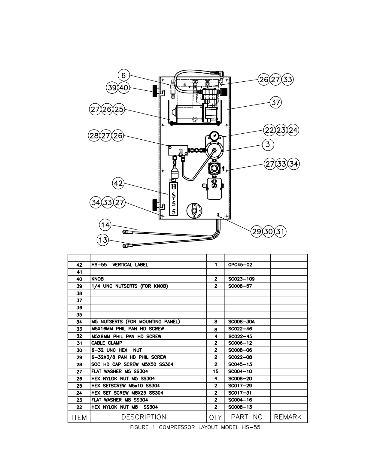
HS-55 to verify all components and connections are secure. For more details about HS-55
Purge System (see page 8 to 13 for item details ).
III TESTING YOUR SYSTEM
Before installing the HS-55, you may wish to test the system prior to going to the field. Testing
the HS-55 will familiarize you with the compressor in an environment where it is easy to work.
The HS-55 is designed to be mounted in a vertical position. The water /oil separator will not
function properly if the unit is in a horizontal position. Once the HS-55 is positioned, connect
the power leads to an appropriate power supply (12VDC, 38 Amp Hour minimum). Turn on power
switch to start the compressor pumping. The pump will take approximately 4 minutes to fill the
air tank to maximum pressure of 85 p.s.i, (600 Kpa) and will then automatically switch off.
Connect to the outlet port (see figure 6) a short piece of river line tubing and secure the end into
a container of water. Check the bubble rate setting as required (factory setting is equivalent to 80
bubbles per minute). If the bubble rate requires adjustment, (see page 16 for instructions).
Please note, if the HS-55 is to be tested without a pressure transducer fitted, then the red valve on
the instrument port (see figure 6) is to be closed prior to the test operation commencing.
There are two pressure gauges fitted to the HS-55. The unit attached to the pressure regulator
(figure 2, №44) indicates the set feed pressure (factory set at 400 Kpa) this pressure should be
retained at this setting, however, if adjustment is required, pull the supply regulator knob (figure
2, №49) and turn it until the required setting is achieved, once finished, push the knob back in
place. The second pressure gauge (figure 1, №10) is located on the side of the HS-55, indicates
the air tank pressure.
To test the purge operation, press the red button. Purge duration should be 5 seconds maximum
during testing.
Gas Purge Compressor Issue 7: 16/12/03
© Copyright HS55 100-04

HYDROLOGICAL SERVICES PTY LTD
_______________________________________________________________________________________
IV SPECIFICATION
Power: 12VDC. (38 amp hour battery minimum).
Maximum Current: 17 Amps
Average Current Draw: Approx. 14 mA (Averaged over a week
and based on 60 bubbles/min)
Compressor: Precision Piston
Receiver Capacity: (Air Tank) 13.5 litres (3.5 U.S. Gallons)
Normal Operating Pressure Range: 60 p.s.i, (400 kpa) to 85 p.s.i, (600 kpa)
Duty Cycle: Typically 10 hours per year at 60 bubbles/minute
2 hours per year at 10 bubbles/minute
Maximum Head: 30 metres (100 ft) using 200 metres (656 ft) of river
line.
Note: Water head increases for shorter river lines [i.e. 45
metres (150 ft) of water head with 100 metes (330 ft) of
river line].
Maximum Length: (River Line) 200 Metres (Using 3/8" O.D.x1/8" I.D Tubing)
Maximum Purge Pressure: 85 p.s.i, (600 kpa)
Minimum Purge Pressure: 60 p.s.i, (400 kpa)
Differential Pressure: 3 p.s.i, (20 kpa) to 5 p.s.i, (35 kpa)
Purging: Manual - 3-Way Switching Valve
Bubble Rate: User selectable from 60 to 120 bubbles/minute. (See
page 16 for adjustment details).
Air Dryer: 5 year maintenance free “Self Purging”Hydrophobic
filter
Environment: -30 deg C to +80 deg C (-40 deg C to +80 deg C
optional)
Pressure Connections: Outlet 3/8" dia tube, instrument 1/4 NPT
Adaptor fittings available for most transducers
Mass: Approx. 30 lbs, (13 kg)
Dimensions: 24" H x 12" W x 15" D (610 mm x 305 mm x 380 mm)
Packed Dimensions: 32" H x 16" W x 19" D (810 mm x 410 mm x 480 mm)
Mass: Approx. 70.55 lbs, (32 kg)
Gas Purge Compressor Issue 7: 16/12/03
© Copyright HS55 100-05

HYDROLOGICAL SERVICES PTY LTD
_______________________________________________________________________________________
OPTIONAL ACCESSORIES:
(i) Pressure Transducer (Model W.L 3100/A).
Enclosure: Aluminium diecast weatherproof enclosure IP65
Dimensions: 180 x 105 x 100 mm
Weight: 1.2 kg
Isolation Diaphgram 316 Stainless Steel
Operating range: 0-5, 0-10, 0-15 , 0-20, 0-30 metres water head (
Imperial units also available up to 100 feet range).
Over pressure: 2.67 x ranges
Operating Temperature: WL3100A -40 oC to +70 oC (-40 oF to +158 oF)
WL3100 -30 oC to +70 oC (-22 oF to +158oF)
(Excluding LCD Display)
Humidity : 100 % non condensing
Overall Accuracy: ±0.02 % F.S. BSL
Long Term Stability: Typically ±0.05 % F.S./annum
Pressure Connection: 1/4OTube
Sensor Vent: Vent fitting for Hydrophobic Filters and/or
desiccant packs.
Calibration: Over full range against water head.
Operating Voltage: 9.6 to 16VDC operation ie. from SDI-12 +12 volt
supply
Current Loop
Operating Voltage: 9V to 30V DC for 4-20mA current loop drive (
used as a 2-wire current loop transducer)
LCD Backlight: Powered via SDI-12 port (9.6 to 16 VDC)
LCD Operating Temperature: -20 oC to +60 oC (-4 oF to +140 oF)
Display: range, resolution, time, date and Level reading.
Parameters: User selectable via push buttons on the pressure
transducer housing
LCD Operation: LCD display is standard with auto shutdown after
Gas Purge Compressor Issue 7: 16/12/03
© Copyright HS55 100-06

HYDROLOGICAL SERVICES PTY LTD
_______________________________________________________________________________________
35 seconds idle.
Power Consumption: Low standby power < 20 microamps (excluding 4-
20mA loop & LCD)
Operating Power: 10mA from SDI-12 supply while taking a
measurement and 0.5mA between measurements.
Options: All options are user programmable via the SDI-12
interface and saved in an on board EEPROM.
Units: Metric or Imperial scaling - (specify when
ordering).
Output: RS232, SDI-12 and 4-20mA output
(ii) Pressure Transducer (Model W.L 2100 Dry).
Accuracy: +/- 0.05% B.S.L
Operating Temp: -20 deg C to +60 deg C (-4 oF to +140 oF)
Combined non linearity,
Hysteresis and Repeatability: +/- 0.05% of full scale
Long term stability: +/- 0.03% full scale per annum
Compensated temp. Range: -20 deg C to +60 deg C (-4 oF to +140 oF)
(iii) Pressure Line 1/8" I.D. x 3/8" O.D. heavy wall black
polyethylene.
SC078-01 - 300M (1000 Ft) Roll
SC078-06 - 100M (328 Ft) Roll
(iv) Orifice Fitting 1) Copper swivel fitting to mount on 2" G.W.I.
pipe (BU07)
2) Gas Chamber Orifice (GCO)
(v) Mounting Bench mounting bracket available
Gas Purge Compressor Issue 7: 16/12/03
© Copyright HS55 100-07


HYDROLOGICAL SERVICES PTY LTD
_______________________________________________________________________________________
V INSTALLATION
(i) Installing the Model HS-55
For proper installation of the HS-55, you will need:
CThe HS-55
CThis Instruction Manual
CInstallation Kit (provided)
Installation for your HS-55 may vary according to your application.
Figure 6 illustrates the physical input/output connections on your HS-55. This drawing will help
in determining where you should make your connections for power, ground, communications,
outlet to orifice and pressure to your sensor
(ii) Field Installation
(i) The HS-55 must be wall mounted in a vertical position, with the compressor at the
top. A mounting bracket can be provided for bench mounting (see drilling template page
17).
(ii) Connect your pressure sensor directly to the manifold or connect a pressure line between
the manifold and your pressure measurement device. If your measurement device has non-
compatible connections, you will need to request adaptor fittings to suit. The manifold port
for the transducer is ¼ BSP
(iii) The HS-55 requires only one power source to power the compressor. This supply is
typically a 12V, 38 amp hour minimum, long life re-chargeable battery with solar or mains
charger.
(iv) Connecting a Pressure Sensor
The pressure sensor can be fitted directly to the manifold or connected using pressure fittings and
connecting tube.
Figure 7 shows typical installations of a complete pressure measurement system.
Gas Purge Compressor Issue 7: 16/12/03
© Copyright HS55 100-014


HYDROLOGICAL SERVICES PTY LTD
_______________________________________________________________________________________
VII MAINTENANCE
The HS-55 is almost maintenance-free. You will need to ensure that your power supply is
sufficient for the equipment that you have installed. (See Specification Page HS-55 100-06).
As the compressor pump’s duty cycle is a few minutes every 48 hours (set at 80
bubbles/minutes), it will last for many years. The voltage sensor prevents the HS-55 from
running from running the battery voltage below 11 Volts for long periods of time. This will
protect the pump and many other components of the HS-55 in case of a system leaks or other
malfunctions.
All fittings must be secure. At 80 bubbles/minutes, even a tiny leak will allow the entire gas
flow to escape.
VIII BUBBLE RATE ADJUSTMENT
The chart below has been prepared to show the relationship between the bubble rate at the test
orifice and the equivalent rates that would be observed on a sight glass bubble unit.
Once the desired bubble rate has been achieved tighten the screw to lock the metering valve.
Bubble rate at Equivalent Sight
Test Orifice Glass Rate
15 60
21 80
27 100
35 120
Note: Bubble rates detailed above are only an approximate guide for the purpose of conserving
gas and have no influence on the performance of the transducer.
Example: To adjust the HS-55 to the equivalent of 80 bubbles per minutes, the metering valve
should be rotated anticlockwise if the bubble rate is below this amount, or clockwise if bubble
rate is above 80 per minute. There should be 21 bubbles per minute emerging from the test
orifice.
Gas Purge Compressor Issue 7: 16/12/03
© Copyright HS55 100-018

HYDROLOGICAL SERVICES PTY LTD
_______________________________________________________________________________________
IX FAULT FINDING
(i) HS-55 Not Powering Up
(a) Check battery voltage
(b) Check all connections including POWER and GROUND. Both the compressor and
control power sources must be connected.
(ii) Intermittent Operation
CCheck your power and ground connection. Moisture over time, will oxidize and
corrode connectors and pins;
CVerify your power supply or battery voltage.
X DRILLING TEMPLATE
(See page 20).
Gas Purge Compressor Issue 7: 16/12/03
© Copyright HS55 100-019

HYDROLOGICAL SERVICES PTY LTD
_______________________________________________________________________________________
Gas Purge Compressor Issue 7: 16/12/03
© Copyright HS55 100-020
Table of contents
Popular Air Compressor manuals by other brands

EINHELL
EINHELL TC-AC 400/50/8 Original operating instructions

California Air Tools
California Air Tools 1P1060S owner's manual

Speedaire
Speedaire 1WC95 Operating instructions and parts manual

Hanbell
Hanbell RC2 Series Technical manual

EUROPE PROJECTION
EUROPE PROJECTION EUROPRO 50TR user manual

Bisonte
Bisonte SC008-009 user guide