HYDROO HDROO Series User manual

HYDROO Pump Industries SL
HF
HX
HN
Light Horizontal
Multistage
Centrifugal Pump
Operation
Manual
HDROO SERIES

2 3
DECLARATION OF CONFORMITY
Machinery Directive: 98/37/EC, 2006/42/EC
Low Voltage Directive: 2006/95/EC
Electromagnetic Compatibility Directlve: 2004/108/EC
Name of manufacturer or supplier
HYDROO PUMP INDUSTRIES, S.L.
Full postal address including country of origin
C/ La Banyeta Nova, 11 - P.I. La Banyeta, 17843 Palol de Revardit (Girona) - Catalonia - Spain
Description of product
HF/HX/HN is a kind of horizontal multistage non-self priming multistage centrifugal pump.
Name, type or model, batch or serial number
Name: Light Horizontal Multistage Centrifugal Pump
Model: HDROO SERIES (HF, HX, HN)
Standards used, including number, title, issue date and other relative documents
Machinery directive 98/37/EC Ecodesign Directive 2009/125/EC
Machinery directive 2006/42/EC - Commission Regulation 547/2012
- Standard: EN809:1998 + A1:2009 - Commission Regulation 640/2009
Place of Issue
Palol de Revardit, Spain
Name of authorlsed representative
Miquel Coma
Position of authorlsed representative
CEO
Declaration
I declare that as the authorised representative, the above information in relation to the supply /
manufacture of this product, is in conformity with the provisions of the above Dlrectlves. For the
most specific risks of this machine, safety and compliance with the essential requirements of the
Directive has been based on elements of the above standards.
Authorized representative
Miquel Coma
CEO
I. AppLICATIONS AND CONDITIONS 4
II. DEFINITION OF MODEL 5
III. CONSTRuCTION 6
IV. INSTALLATION AND CONNECTION 8
V. START-up, OpERATION AND MAINTENANCE 11
VI. ASSEMbLE AND DISASSEMbLE 12
VII. FAuLT FINDINg AND SOLuTION CHART 13
VIII. IMpORTANT NOTICE 15
CONTENTS

4 5
Read this manual carefully
before install, start the pump.
I. AppLICATIONS AND CONDITIONS
HF, HX, HN are non-self-priming light horizontal multistage
centrifugal pump (abbr. as pump in the following). They are efficient, low noise,
little corrosive tolerance, compact structure, good looking, small volume,
light weight, etc.
1. Applications
· Pumped liquids: Low viscosity, neutral, non-explosive liquids, not
containing so lid particles or fibres. The liquid must not attack the pump
materials chemically. (Oil or the liquid mainly consisted of oil can be pumped
by special type of pumps);
· Circulation for air condition system;
· Cooling system;
· Water treatment, purification system;
· Industry cleaning system;
· Liquid transferring, circulation, boosting;
· Hot or cold water;
· Feed proportioning system of food, drinking, agriculture, etc.
2. Operation conditions
· Liquid temperature: Normal temperature type -15ºC~+70ºC ;
Hot water type -15ºC ~+ 110ºC;
· Flow range: 0.5~28 m3/h
· Max pressure: 10 bar
· Liquid pH range: pH5 ~9
· Max ambient temperature: +40ºC
· The Max suction pressure is limited by max operating pressure;
· Min inlet pressure: Refer to HDROO catalogue.
Caution: When pumping liquids with a density and/or viscosity higher
than that of water, use motors with correspondingly higher outputs, if
required.
II. DEFINITION OF MODEL
H F 4 40 S 5 20’75 0023
Number of poles
5: 50 Hz
6: 60 Hz
Rated voltage (x10) (V)
S: one phase
T: three phases
Power P2 (kW)
Normal temperature omitted
R:High temperature
Number of stages(x10)
Rated flow (m³/h)
F: cast iron version
X: SS304wet parts
N: SS316 wet parts
Horizontal Multistage
Centrifugal Pump
-

6 7
III. CONSTRuCTION
· Pump is horizontal, multistage, section type. Pump shaft is the extended
motor shaft. Axial suction and radical discharge;
· HDROO Series are mainly composed of motor, suction head, discharge head,
diffuser, impeller, pump shaft, mechanical seal, etc.
· The key parts of pump---diffuser, impeller, inlet and outlet chamber,
pump shaft are made of stainless steel. The suction head and discharge head
of HF is made of cast iron.
· Mechanical seal is single face seal. Seal part is made of Silicon Carbide/
Carbide. Other material for Seal part is also available on demand of
customers.
· The standard connection type is pipe thread connection, which is conformable
with GB7307 standard. See the following pump structure figure.
HF, HX, HN 2 4-080701
Fig. 1B HF, HX, HN 2, 4 Pump structure
1. Suction
2. Plug
3. Bearing (W/O this part
in 2-3 stages pump)
4. Impeller
7. Discharge
8. Mechanical Seal
10. Base plate
11. Staybolt
12. Diffuser
12a. Neck ring retainer
12b. Neck ring
13. Support diffuser (W/O this
part in 2-3 stages pump)
14. Impeller sleeve
15. Sleeve 1 (W/O this part
in HF,HX, HN 2)
17. Seal ring
18. Impeller sleeve(S) (W/O
this part in 2-3 stages pump)
19. First impeller cover
20. Nut
23. O ring
24. Spring washer
25. Nut
28. Screw
29. Spring Washer
31. Washer
32. Motor
HF, HX, HFN 8, 12, 16, 20-080701
Fig. 1D HF, HX, HN 8, 12, 16, 20 Pump structure
1.- Suction
2.- Plug
3.- Bearing (W/O this part
in 1-2 stages pump)
4.- Impeller
7.- Discharge
8.- Mechanical Seal
10.- Base plate
11.- Staybolt
12.- Diffuser
(W/O this part in HF, HX, HN
20 1-3 stages pump)
12a.- Neck ring retainer
12b.- Neck ring
12c.- Last diffuser
(Only for HF, HX, HN 20)
13.- Support diffuser
(W/O this part in 1-2 stages
pump)
14.- Impeller sleeve
15.- Impeller sleeve(L)
(W/O this part in 1-2 stages
pump)
17.- Seal ring
18.- Impeller sleeve(S)
(W/O this part in 1-2 stages
pump)
19.- First impeller cover
20.- Nut
23.- O ring
24.- Washer
2S.- Nut
28.- Screw
29.- Spring washer
31.- Washer
32.- Motor

8 9
IV. INSTALLATION AND CONNECTION
1. Installation
· Pump should be sited in a well ventilated but frost-free position. The
distance between pump with motor and other objects should be at least 150mm,
in order to cool the motor by fan with enough air.
· To reduce the head loss of inlet as least as possible, the inlet pipe shall
be as short as possible.
· Ensure the check valve is installed in pipe line system before the pump
installation to prevent liquid from returning.
· Pump should be fixed in ground or fixed on the brackets on wall. Pump
should be safely flxed and stable. Pay attention not to let the weight of pipe
system on pump to prevent pump from damage.
· Before pump installation. the inlet pipeline shall be cleaned. If there
is impurities in the pipe, it is necessary to install a strainer at 0.5-1mm in front
of the pump inlet.
· The air pockets shall be avoided when installing the inlet pipe line. See Fig. 2
Air Air
Air
Wrong Correct
· It is necessary to flt a pressure meter to observe and control operation
of pump.
· When the height of pump position is higher than liquid level, in the suction
range of pump, a foot valve should be installed in the inlet pipe end.
And fit a water pouring screw hole in the drainage pipe. It is used for pouring
water in before starting pump.
2. Electrical connection
· The electrical connections should be carried out by a qualified electrician.
· To make sure the motor is suitable for the power supply, cables ofthe
motor must be connected to power supply according to the Fig. on the terminal
box and the motor nameplate.
· Motor shall be connected with a fast and effective motor starter, to ensure
that the motor will not be damaged by lack of phase, unstable voltage
or overload. The motor shall be earthed reliably.
Caution: Before take apart the terminal box cover or dismantle pump, make
sure that the power supply is switched off.
Warning - Electrical connection and safety devices
· The pump units should be connected to the power supply by the appropriately
rated power cables according to the motor ratings.
· The pump units should always be equipped with safety devices as required
in the standards (EN 809 and/or EN 60204-1) as well as by the national
rules of the country where the pump is used.
· Despite the rules of any country, the power supply to the pump unit
must be equipped with at least following electrical safety devices with appropriate
ratings:
- Emergency switch
- Circuit breaker (as a supply disconnecting (isolating) device as well as an overcurrent
protective device)
- Motor overload protection
The following table is for suggestion:
3 phase motors:
Single phase motors:
The acoustic noise emission is around 75 dB (A).
Before open the terminal box, please shut off the power
supply to prevent from power shock.
380V (50Hz/60Hz)
No. Power input (Kw) Cable
connection
Input
current (A)
Cable spec
(mm2)
Circuit breaker
(A)
Thermal
protector (A)
10.37 Y 1 0.75 51.2
20.55 Y1.4 0.75 51.7
30.75 Y1.8 0.75 52.2
41.1 Y2.6 1 5 3.1
61.5 Y3.5 110 4.2
82.2 Y4.9 1.5 10 5.9
11 36.3 1.5 10 7.6
13 48.2 2.5 20 9.8
15 5.5 11 2.5 20 13.2
IE1 MOTOR 230 V 50 Hz
Type Current (A) Power (kW) Speed (rpm) Efficiency (%)
YY-711-2 2,37 0,37 0.75
YY-712-2 3,88 0,55 0.75
YL-801-2 5,15 0,75 0.75
YL-802-2 7,02 1,1 2900 1
YL-90S-2 9,44 1,5 1
YL-90L-2 13,67 2,2 1.5

10 11
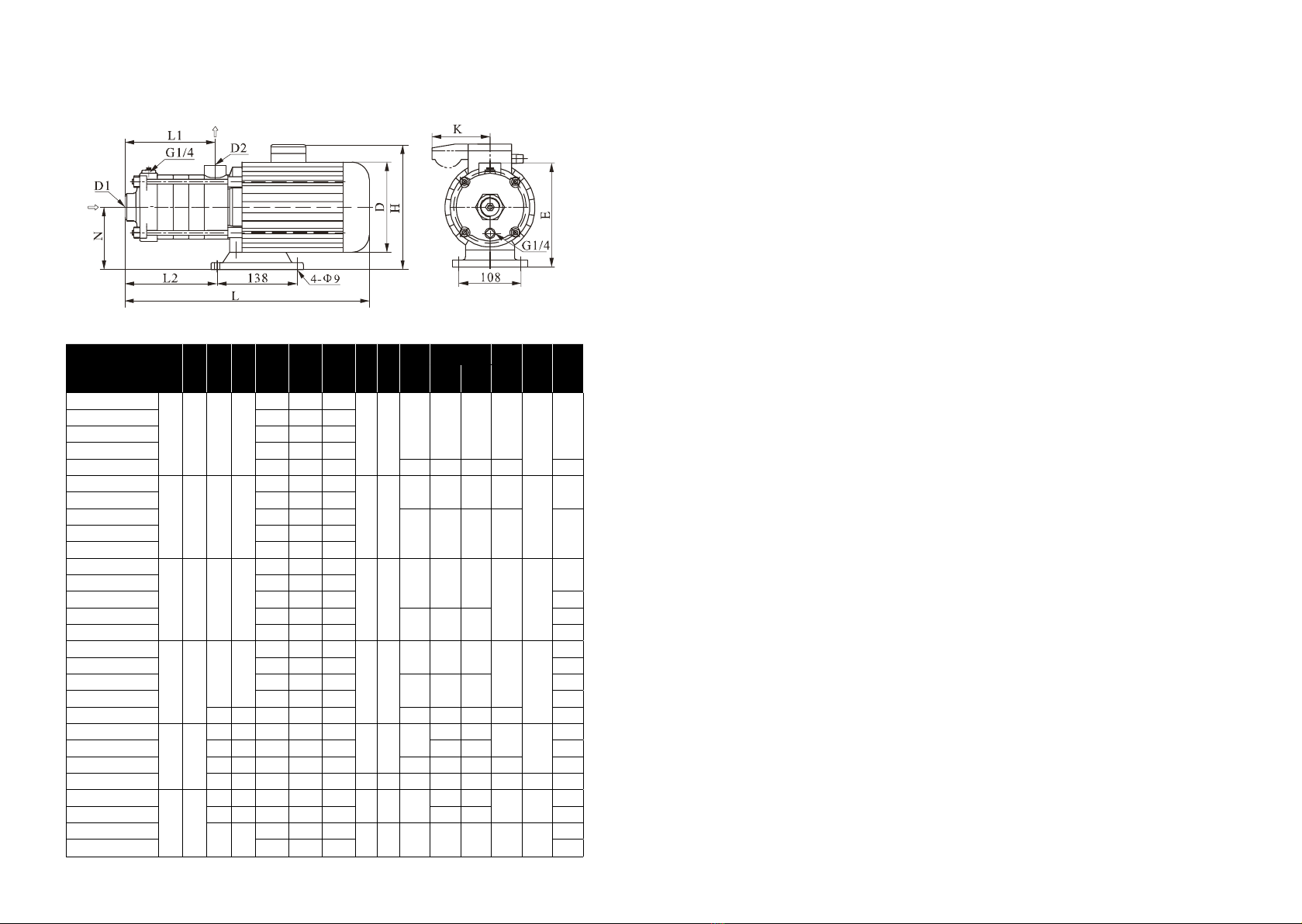
3. HF, HX, HN dimensions (mm)
Model D1 D2 N E L L1 L2 L3 d D
H K
M
weight
Three
phase
Single
phase
Single
phase Kg
HF, HX, HN 2-20
G1 G1 110 182
305 84 87
138 9145 215 230 96 108 15
HF, HX, HN 2-30 323 102 105
HF, HX, HN 2-40 341 120 123
HF, HX, HN 2-50 359 138 141
HF, HX, HN 2-60 422 156 159 170 225 245 100 17
HF, HX, HN 4-20
G1¼ G1 110 182
329 102 105
138 9
145 215 230 96
108
15
HF, HX, HN 4-30 356 129 132
HF, HX, HN 4-40 416 156 162
170 225 245 100 17HF, HX, HN 4-50 455 183 188
HF, HX, HN 4-60 482 210 213
HF, HX, HN 8-10
G1½ G1¼ 118 228
395 108 126
138 9
170 230 265
100 108
20
HF, HX, HN 8-20 395 108 126
HF, HX, HN 8-30 425 138 156 25
HF, HX, HN 8-40 490 168 186 180 240 270 28
HF, HX, HN 8-50 520 198 216 30
HF, HX, HN 12-10
G1½ G1½ 118 268
395 108 126
138 9
170 230 265
100 108
20
HF, HX, HN 12-20 395 108 126 21
HF, HX, HN 12-30 460 138 156 180 240 270 25
HF, HX, HN 12-40 490 168 186 29
HF, HX, HN 12-50 126 240 555 198 216 195 270 / / 34
HF, HX, HN 16-10
G2 G2
117 227 423 126 151
138 9180 230 265 100 108
18
HF, HX, HN 16-20 118 228 455 126 151 240 270 27
HF, HX, HN 16-30 130 240 561 171 196 195 270 / / 33
HF, HX, HN 16-40 120 230 621 216 340 140 12 220 270 / / 190 41
HF, HX, HN 20-10
G2 G2
117 227 423 126 151 138 9180 230 265 100 108 18
HF, HX, HN 20-20 118 228 455 126 151 240 270 27
HF, HX, HN 20-30 120 230 576 171 294 140 12 220 270 / / 190 41
HF, HX, HN 20-40 621 216 340 44
V. START-up, OpERATION AND MAINTENANCE
Caution: It is prohibited to run without liquid, which will damage mechanical
seal and sliding bearing.
1. Do not start the pump until it has been filled with water or liquid fully.
· Fill water in pump in inverse pouring system.
Close the pump outlet valve, release air vent screw on the pump head, and open the
inlet valve slowly until stable water flows from the air vent screw.
Then fasten the screw.
· Fill water in pump when liquid level is lower than pump. Before installing,
pump and pipes must be filled with liquid fully and air vented.
2. Check the rotary direction
Switch on the power supply and view the rotary direction by viewing the
motor fan. From the motor end, pump shall run counter-clockwise.
3.Check before pump start-up
· Check whether the pump is fixed securely.
· Check whether pump is filled with water fully and check whether liquid
can flow freely.
· Check whether the voltage of power supply is stable.
· Check whether it turns correctly.
· To make sure all pipe lines are connected tightly and can supply water
normally.
· The valves in the inlet pipe line are completely opened.
· The outlet valve shall be opened slowly after the pump is started up.
· Check the operation pressure if pressure meter is installed.
· Check all the controls for normal operation. If the pump is controlled
by pressure switch, check and adjust the starting pressure and stopping pressure.
Check the full load current to make sure it not surpasses the max allowed
current.
4. Frequency of pump starts
· Pump should not be started too frequently. It is suggested pump shall
not be started more than 100 times per hour if the motor power is less or equal
to 4kW. When motor power is big than 4kW, pump shall not be started
more than 20 times in one hour.
· Suggestion: When pump running, flow should be controlled at the range
of 0.5-1.3 times of rated flow.
· There should be no noise when pump running. If there is something
wrong, stop pump and check it and repair.

12 13
5. Frost Protecting
Pump can be used in the system with anti-frozen measures. If the pump
is installed in easily frozen environment, suitable antifreeze shall be added
to the transferring liquid to prevent pump from being damaged. If antifreeze
is not used, pump shall not be used during periods of frost. Pump should be
drained when stops using.
6.The following should be checked regularly for pump
· Pump working and operating pressure
· Possible leakage
· Possible motor overheat
· Cleaning/replacement of all strainers (If strainers fit)
· The switch off time of motor overload
· Frequency of starts and stops
· All control operation
If find faults, check system according to “Fault Finding and Solution chart”.
· Pump shall be cleaned and kept appropriately when it is not used for
a long time.
· Pump shall be prevented from being corrupted and damaged in storage.
VI. ASSEMbLE AND DISASSEMbLE
HF, HX, HN
· Fit discharge head on the motor. Fit mechanical seal. The faces of mechanical
seal should be lubricated.
· Fit the impellers, diffusers etc. in position according to the drawing.
Then fit impeller cover, tighten nuts, fit seal circle on every diffusers.
· Fit suction head, stay bolts, tighten the nuts of stay bolts.
· Rotate the motor fan by hand to ensure that the shaft is not choked.
Reverse the process above can disassemble a pump.
VII. FAuLT FINDINg AND SOLuTION CHART
Caution: Before removing the terminal box cover and before any removal /
dismantling of the pump, make sure that the power supply has been switched
off.
Fault Cause Solution Remarks
Motor does not run
when started
a) Power supply failure. a) Check power supply.
b) Fuses are blown. b) Replace fuses.
c) Motor is overloaded. c) Check system.
d) Main contacts of starter are
not connected well or the coil
is defective.
d) Replace motor starter.
e) Control circuit is defective. e) Check control circuit.
f) Motor is defective. f) Repair.
Overload device of
motor starter trips out
immediately when
power supply
is switched on
a) Fuses are blown. a) Replace fuses.
In the case of
d) and e), users shall
not disassemble the
pump by themselves.
b) Contacts of overload device
are faulty. b) Check motor starter.
e) Cable connection is loose
or faulty.
c) Check cables and
power supply
d) Motor winding is defective. d) Replace motor
e) Pump mechanically blocked. e) Check and repair
pump
Overload device trips
out occasionally
a) The setting of overload is
too low. a) Reset overload setting
b) Periodic power supply faults. b) Check power supply
c) Low voltage at peak times. c) Add regulator.
Motor starter has
not tripped out but
the pump does not
run.
a) Contacts of starter are not
contacted well or the coil is
faulty.
a) Change motor starter
b) Control circuit are defective b) Check control circuit

14 15
Continued
Fault Cause Solution Remarks
Pumped water does
not flow constantly
a) Suction pipe is too small. a) Enlarge inlet pipeline
b) There is not sufficient water
in pump water inlet.
b) Improve system and
increase coming water
c) Liquid level is Iow. c) Try to lift liquid level.
d) Pump inlet pressure is too
low compared with water
temperature, pipeline loss
and flow.
d) Improve system and
try to increase the inlet
pressure.
e) Suction pipe is partly
blocked by impurities.
e) Check and clear
impurities.
Pump runs but gives
no water
a) Suction pipe is blocked by
impurities.
a) Check and clean
suction pipe.
b) Foot valve or check valve is
closed.
b) Check and repair foot
valve or check valve.
c) Leakage in suction pipe. c) Check and repair
suction pipe.
d) There is air in suction pipe
or pump.
d) Refill liquid,
release air.
Pump runs
backwards when
switched off
a) Leakage in suction pipe. a) Check suction pipe
b) Foot valve or check valve is
defective.
b) Check and repair foot
valve or check valve.
c) Foot valve is blocked in
opened or partly opened
position.
c) Check and repair foot
valve.
d) There is air in suction pipe.
d) Check and repair
suction pipe and
release air.
Fault Cause Solution Remarks
Abnormal vibration
or noise from pump
a) Leakage in suction pipe. a) Check and repair
suction pipe
In the case of e),
users shall not
disassemble
the pump by
themselves.
b) Suction pipe is too small or
suction pipe is partly blocked
by impurities.
b) Enlarge or check
suction pipe.
c) There is air in suction pipe
or pump.
c) Refill liquid to the
pump and vent air.
d) The comparison of the
delivery head of device with
delivery head of pump is very
low.
d) Improve system or
choose another pump
model.
e) Pump mechanically
blocked.
e) Check and repair
pump.
Continued
VIII. IMpORTANT NOTICE
1. Customers will not be advised if this manual is updated.
2. Pump will be guaranteed for one year under normal operation with the correct
model. Wearing part is not included.
3. Users shall be responsible for the damage if they disassemble the pumps by
themselves in guaranteed period.

Be pumping partners
201902-IOM-HFHXHN-EN
subject to amendments
HYDROO Pump Industries SL
C/ La Banyeta Nova, 11 - P.I. La Banyeta,
17843 Palol de Revardit (Girona) - Catalonia - Spain
Tel. +34 972 394 654
E-mail: info@hydroo.com
www.hydroo.com
This manual suits for next models
3
Table of contents
Other HYDROO Water Pump manuals
Popular Water Pump manuals by other brands

SHURflo
SHURflo 200 Series installation manual

Homelite
Homelite UT40520 Operator's manual

Arcomed
Arcomed Volumed uVP7000 Premium Service manual

Dover
Dover Wilden Original PV20 Engineering, operation & maintenance

Pentair
Pentair Myers BX Series Installation and service manual

DAYLIFF
DAYLIFF DDW 400S Installation & operating manual