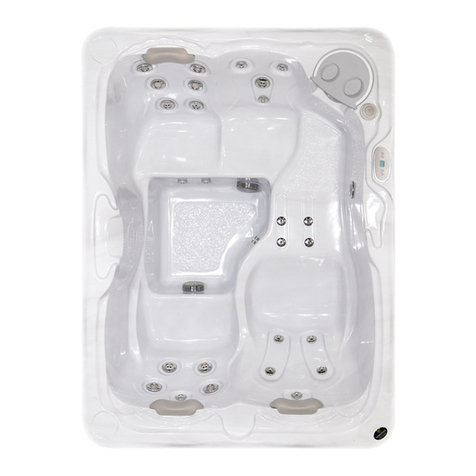
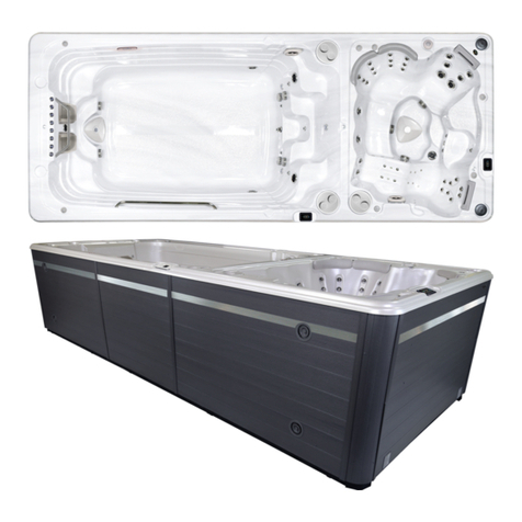
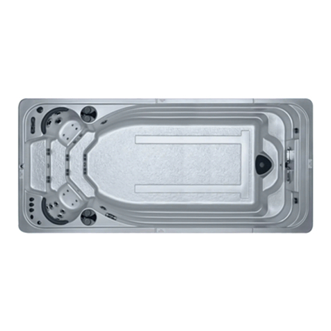
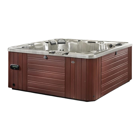
Hydropool Self Clean 395 Gold User manual

2
Models Covered Domestic
Model Codes Export
Model Codes
Self Clean 395 Gold HSC395G HSCE395G
Self Clean 495 Gold HSC495G HSCE495G
Self Clean 495 Platinum HSC495P HSCE495P
Self Clean 570 Gold HSC570G HSCE570G
Self Clean 570 Platinum HSC570P HSCE570P
Self Clean 670 Gold HSC670G HSCE670G
Self Clean 695 Gold HSC695G HSCE695G
Self Clean 670 Platinum HSC670P HSCE670P
Self Clean 695 Platinum HSC695P HSCE695P
Self Clean 720 Platinum HSC720P HSCE720P
Self Clean 770 Platinum HSC770P HSCE770P
Self Clean 970 Titanium HSC970T HSCE970T
Self Clean 790 Platinum HSC790P HSCE790P

3
Letter of introduction 4
Important User Safety Instructions
Warnings 5
Hyperthermia 6
Choosing the Right location
Indoor Locations 7
Outdoor Locations 7
General Installation Considerations 8
Special Considerations
Indoor Installations 9
Outdoor Installations 9
Site Preparation
Above Ground Installations 9
In-ground & Partial In-ground Installations 10
Overall Support (non-cabinet installations) 10
Equipment Accessibility & Protection 11
Unloading/Handling your Hot Tub 11
Important Electrical Safety Instructions 12
G.F.C.I./R.C.D. Application Guideline 12
Wire Size 13
North America G.F.C.I. Installation Diagram 14
Europe R.C.D. Installation Diagram 15
Filling, Checking and Starting your Hot Tub 16-17
Pump Priming/Releasing an Air Lock 16-17
Hydropool Control Systems 18-25
IN.YE / IN.YT Spa Pack Series 18-38
I-Command 2 System (optional) 26
Standby Mode / Drain Mode 37
Hydrother Control / Wellness Package (optional) 37
Topside Panel Display Messages 38
Optional Variable Air Therapy System 38
Hydroclear Pure Water System 39
Hot Tub Water Balance
General Overview 40
Initial Fill 40
Glossary of Common Water Maintenance Terms 41
Water Balance Summary for your Hot Tub (chart) 41
Water Balance Troubleshooting 42
Routine Hot Tub Maintenance
Daily, Weekly, Monthly, Quarterly 43
Cleaning the Skimmer Basket 43
Safety Hard Cover 43
Cartridge Filter, Removal, Cleaning, Re-installation 44
Cleaning the Acrylic Surface 44
Changing your Hot TubWater 45
Draining your Hot Tub Water 45
Hydropool Exclusive Quick-Drain™ 46
Self-Cleaning Mode Indicator 46
Everlast Products
Protecting your Cabinet Everlast Finish 47
Winterizing your Hydropool Hot Tub 48
General Troubleshooting 49
What to do in the event of
Power Fluctuations 49
Cold Weather Power Failure 49
Wiring Diagrams (in.ye / in.yt ) 50-55
NOTE: Product specifications, warnings and labels are subject to change without notice. This user’s manual
should be used as a guide only. For further information, please contact your independent Hydropool dealer.
TABLE OF CONTENTS

4
On behalf of everyone at the company, we thank you for your decision to purchase a
Hydropool hot tub.
Recognized for quality worldwide, we are confident that your new hot tub will provide you,
your family and friends, with years of enjoyment and fulfill all your hydrotherapy needs.
Hydropool hot tubs are not only healthful and relaxing, they can even add value to your home.
Please take the me to carefully read and understand all the safety, installaon and
operang instrucons in this manual before electrically connecng your hot tub and adding
water.
The following pages contain valuable informaon and pointers that will save you both me
and money, as well as help you to simplify upkeep and maintenance.
Since we manufactured our first hot tub in 1985, the Hydropool team has been dedicated to
producing a quality product catering to maximum hydrotherapy, comfort, energy efficiency
and ease of operaon.
We are confident that as you become more familiar with the various safety and maintenance
features of your new hot tub you will be sasfied that you made the right decision in
purchasing a Hydropool hot tub.
Happy hot tubbing...
David Jackson

5
SAVE THESE INSTRUCTIONS
IMPORTANT SAVE THESE INSTRUCTIONS
Your physiological response to hot water is subjecve and depends on your age, health, and medical history. If you don’t
know your tolerance to hot water, or if you get a headache, or become dizzy or nauseous when using your hot tub, get out
and cool off immediately.
WARNING
1. CHILDREN SHOULD NOT USE SPASOR HOT TUBS WITHOUT ADULT SUPERVISION.
2. DO NOT USE SPASOR HOT TUBS UNLESS ALL SUCTION GUARDS ARE INSTALLED TO PREVENT BODY AND HAIR
ENTRAPMENT.
3. PEOPLE USING MEDICATIONS AND/OR HAVING ANY ADVERSE MEDICAL HISTORY SHOULD CONSULT A PHYSICIAN
BEFORE USING A SPA OR HOT TUB.
4. PEOPLE WITH INFECTIOUS DISEASES SHOULD NOT USE A SPA ORHOT TUB.
5. TO AVOID INJURY,EXERCISE CARE WHEN ENTERING OR EXITING THE SPA OR HOT TUB.
6. DO NOTUSE DRUGS ORALCOHOL BEFORE OR DURING THE USE OF A SPA ORHOT TUB, TOAVOID UNCONSCIOUSNESS
AND POSSIBLE DROWNING.
7. PREGNANT OR POSSIBLE PREGNANT WOMENSHOULD CONSULT A PHYSICIAN BEFORE USING A SPA ORHOT TUB.
8. WATER TEMPERATURE IN EXCESS OF 38°C (100°F)MAY BE INJURIOUS TO YOUR HEALTH.
9. BEFORE ENTERING THE SPAOR HOT TUB, MEASURE THE WATER TEMPERATURE WITH ANACCURATE THERMOMETER.
10. DO NOT USE A SPA OR A HOT TUB IMMEDIATELY FOLLOWING STRENUOUS EXERCISE.
11. PROLONGED IMMERSION IN ASPAOR HOT TUBMAY BE INJURIOUSTO YOUR HEALTH.
12. DO NOT PERMIT OR USE ELECTRIC APPLIANCES (SUCH AS LIGHT, TELEPHONE, RADIO OR TELEVISION) WITHIN 1.5M
(5FT) OF THIS SPA OR HOT TUB.
13. CHILDREN SHOULD NOT ENTER A HOT TUB WHERETHE WATER TEMPERATUREEXCEEDS BODY TEMPERATURE (37°C /
98.6°F).
14. DO NOT ALLOW CHILDREN TO SUBMERGE THEIR HEAD UNDER WATER.
15. NEVER OPERATE THE HOT TUB PUMP AT HIGH SPEED WITHOUT HAVING ALL SUCTION AND RETURN LINES OPEN.
16. ALWAYS KEEP THE HARDCOVER INSTALLED AND LOCKED WHEN THE HOT TUB IS NOT IN USE.
17. TEST THE GFCI (GROUND FAULT CIRCUIT INTERRUPTER) MONTHLY.
18. POST EMERGENCY PHONE NUMBERS FOR POLICE, FIRE DEPARTMENT, AND AMBULANCE AT THE NEAREST PHONE.
19. TO REDUCE THE RISK OF INJURY
THE WATER IN A SPA SHOULD NEVER EXCEED 40°C (104°F). WATER TEMPERATURES BETWEEN 38°C (100°F) AND
40°C (104°F) ARE CONSIDERED SAFE FORA HEALTHYADULT. LOWER WATER TEMPERATURES ARE RECOMMENDED
FOR YOUNG CHILDREN AND WHEN SPA USE EXCEEDS 10 MINUTES.
SINCEEXCESSIVE WATER TEMPERATURES HAVE A HIGHPOTENTIAL FOR CAUSINGFETAL DAMAGE DURING THE
EARLY MONTHS OF PREGNANCY, PREGNANT OR POSSIBLY PREGNANT WOMEN SHOULD LIMIT SPA WATER
TEMPERATURES TO 38°C (100°F).
BEFORE ENTERING A SPA, THE USER SHALL MEASURE THE WATER TEMPERATURE SINCE THE TOLERANCE FOR
WATER TEMPERATURE-REGULATING DEVICES VARIES.
THE USE OF ALCOHOL, DRUGS, OR MEDICATION BEFORE OR DURING SPA USE MAY LEAD TO UNCONSCIOUSNESS,
WITH THE POSSIBILITY OF DROWNING.
OBESE PERSONS AND PERSONS WITH A HISTORY OF HEART DISEASE, LOW OR HIGH BLOOD PRESSURE,
CIRCULATORY SYSTEM PROBLEMS OR DIABETES SHOULD CONSULT A PHYSICIAN BEFORE USING A SPA.
PERSONS USING MEDICATION SHOULD CONSULT A PHYSICIAN BEFORE USING A SPA SINCE SOME MEDICATION
MAY INDUCE DROWSINESS WHILE OTHER MEDICATION MAY EFFECT HEART RATE, BLOOD PRESSURE AND
CIRCULATION.
6
SAVE THESE INSTRUCTIONS
IMPORTANT SAVE THESE INSTRUCTIONS
Your physiological response to hot water is subjecve and depends on your age, health, and medical history. If you don’t
know your tolerance to hot water, or if you get a headache, or become dizzy or nauseous when using your hot tub, get out
and cool off immediately.
CAUTION
1. MAINTAIN WATER CHEMISTRY IN ACCORDANCE WITH THE MANUFACTURER’S INSTRUCTIONS.
DANGER
1. RISK OF ACCIDENTAL DROWNING. EXTREME CAUTION MUST BE EXERCISED TO PREVENT UNAUTHORIZED ACCESS BY
CHILDREN. TO AVOID ACCIDENTS, ENSURE THAT CHILDREN CAN’T USE THE SPA UNLESS THEY ARE SUPERVISED AT ALL
TIMES.
2. RISK OF INJURY. THE SUCTION FITTINGS IN THIS SPA ARE SIZED TO MATCH THE SPECIFIC WATER FLOW CREATED BY
THE PUMP. SHOULD THE NEED ARISE TO REPLACE THE SUCTION FITTINGS OR THE PUMP, BE SURE THAT THE FLOW
RATES ARE COMPATIBLE. NEVER OPERATE THE SPA IFTHE SUCTION FITTINGS ARE BROKEN OR MISSING.NEVER RE-
PLACE A SUCTION FITTING WITH ONE RATED LESS THAN THE FLOW RATE MARKED ON THE ORIGINAL SUCTION FIT-
TING.
3. RISK OF ELECTRICSHOCK. INSTALL AT LEAST 1.5M (5FT) FROM ALL METAL SURFACES. AS AN ALTERNATIVE, A SPA MAY
BE INSTALLED WITHIN 1.5M (5FT) OF METAL SURFACES IF EACH METAL SURFACE IS PERMANENTLY CONNECTED BY A
MINIMUM 8 AWG (8.4mm2) SOLID COPPER CONDUCTOR TO THE WIRE CONNECTOR ON THE TERMINAL BOXTHATIS
PROVIDED FOR THIS PURPOSE.
4. RISK OF ELECTRICSHOCK. DO NOT PERMIT ANY APPLIANCE, SUCH AS A LIGHT, TELEPHONE, RADIO, OR TELEVISION,
WITHIN 1.5M (5FT) OF THE SPA.
HYPERTHERMIA
Since your hot tub can be set to reach temperatures of 40°C (104°F),
users should be aware that extended submersion in water that exceeds
normal body temperature can lead to hyperthermia.
The causes, symptoms and effects of hyperthermia may be described as
follows:
Hyperthermia occurs when the internal temperature of the body
reaches several degrees above the normal body temperature of 37°C
(98.6°F). The symptoms of hyperthermia include drowsiness, lethargy,
and an increase in the internal temperature of the body. The effects of
hyperthermiainclude:
Unawarenessof impending hazard
Failure to perceive heat
Failure torecognize the need toexit the hot tub
Physical inability to exit the hot tub
Fetal damage in pregnant woman
Unconsciousness resulng in the danger of drowning
If you sense any of the symptoms of hyperthermia, safely
exit the hot tub immediately.
WARNING
THE USE OF ALCOHOL, DRUGS
OR MEDICATION CAN
SIGNIFICANTLY INCREASE THE
RISK OF FATAL HYPERTHERMIA.

7
CHOOSING THE RIGHT LOCATION
Your Hydropool hot tub can beinstalled indoors or out, on theground, in the ground or half-and-half. Thefollowing
informaon will assist you in choosing the right locaon for your individual needs. When making your decision, always
remember that hot tubs can be enjoyedyear-round, indoors or out, regardless of the climate. Many Hydropool owners
report that their favourite me to use a hot tub is in the cooler fall and winter months, while others praise the enjoyment
of using their hot tub inthe warmer springand summer months.
If members of your family are not cold weather enthusiasts, or if your backyard or pao area is not suitable for a hot tub
installaon, then an indoor locaon for your hot tub may be your best or only choice. You may wish to create an exercise/spa
area in your home, or install your hot tub in a glass solarium or four-season room adjoining your home. Indoor installaons
not only add a unique look and appeal to your home, they provide the privacy and controlled climate to ensure that use and
enjoyment of your hot tub is maximized. If you should choose an indoor locaon, you will find further informaon as outlined
in the secon “SPECIAL CONSIDERATIONS FOR INDOOR INSTALLATIONS”
INDOOR LOCATIONS
OUTDOOR LOCATIONS
For a variety of reasons, outdoor locaons are a far more popular choice. Some of the reasons include:
• Limited indoor space
• Delivery complicaons due to door openings, stairwells, etc.
• Limited budget (indoor installaons usually also involve interior home renovaons)
• Desire for an outdoor entertainment center
• Hot tub is being installed adjacent to an exisng or planned swimming pool
• Concerns over splashing water inside the home
For those who choose an outdoor locaon, hot tub operang temperatures can be adjusted to match the season. In colder
months, manyowners will operate their hot tub in the range of 38-40°C (100-104°F).
During warmer months, an operang temperature of 36-37°C (97-99°F) will provide a refreshing retreat. If you should choose
an outdoor locaon, you will find further informaon as outlined in the secon “SPECIAL CONSIDERATIONS FOR OUTDOOR
INSTALLATIONS”

8
GENERAL INSTALLATION CONSIDERATIONS
1. Your HYDROPOOL hot tub is a self-contained pre-plumbed unit, so that no on-site plumbing connecons to the
residenal water supply or drain are required.
2. Ensure that your HYDROPOOL hot tub is properly supported by either a level concrete pad, or a properly constructed
deck capable of supporng 1220 kg/m2 (250 lbs./.2). If there is a possibility that the pad could shi by freezing/thawing
ground movement (such as in clay regions, and/or areas with high water tables) concrete foongs extending below the
frost line are recommended.
3. Decking should be chosen and constructed in a manner that minimizes the chance of slipping or falling.
4. If you do not have a factory installed insulated cabinet, it is assumed that you are building your own custom cabinet,
ling or decking.
Please consider the following:
a) Your HYDROPOOL hot tub is self-supporng on its base. The cabinet should be decorave only, not for support. Never
suspend the hot tub from the deck or cabinet.
b) Where the hot tub is not equipped with a factory installed cabinet,it is the installer’s responsibility to ensure all electrical
equipment is completely weather protected and meets all of the regulatory requirements.
c) Always provide adequate access for servicing the support equipment.
d) Decking must be constructed to allow repair access around the enre hot tub.
e) In remote equipment or no-cabinet installaons, you may add extra insulaon, but the equipment area must have
adequate cross-flow venlaon.
5. Installaon of a safety grab rail or reachable support for use when entering or exing the hot tub is recommended.
6. A nearby garden hose connecon is recommended for filling and “topping up” the hot tub.
The hot tub equipment and all electrical plugs, outlets and lights within 1.5m (5) of the hot tub must be G.F.C.I protected.
Consult your electrician or local electrical authority for further details.
Access to the hot tub must always be secured:
Outdoors - in accordance with local property by-laws and/or via an approved fence with a self-closing gate and a safety
hardcover;
WARNING

9
SPECIAL CONSIDERATIONS
INDOOR INSTALLATIONS
• It is beneficial to have the hot tub room located near wash room and shower facilies
• The hot tub room should have a floor drain to handle splash water, a window, outside exhaust fan or humidistat controlled
exhaust fan for venlaon and a humidifier.
• Consider plumbing a water tap and drain locaon nearby to facilitate draining and top-up
• Always provide adequate venlaon for the support equipment
• Consult your local Hydropool retailer for further informaon
OUTDOOR INSTALLATIONS
• Contact your local building code department to determine if a building permit is necessary and for informaon on applicable
bylaws (distance from property lines,buildings, fencing requirements, etc.)
• If you are doing any excavang, contact your local gas, electric, and cable-company to ensure that there are no underground
lines
• Locate the hot tub, where praccal, within close distance of a door to the house to maximize potenal winter use.
• Ensure that all hot tub support equipment is easily accessible and protected fromthe elements
• The hot tub support equipment is designed for indoor (out of the direct elements) use. When your HYDROPOOL hot tub is
equipped with a factory-installed cabinet, and installed as per the guidelines of this manual, the equipment will be
adequately protected. If the hot tub is shipped without a cabinet, your custom cabinet or other structure must be designed
to supply protecon for the hot tub support equipment from rain, snow, splash water, etc., but sll designed in a manner to
ensure adequate venlaon.
SITE PREPARATION
ABOVE-GROUND INSTALLATIONS
Where the hot tub is a “stand-alone” above-ground installaon to be installed in regions where freeze/thaw condions may
occur, a level pao stone or pre-formed paver type base may be sufficient if there is no abung deck(s) that could be
damaged during potenal seasonal movement of the ground. The potenal drawback to this type of base is that splash water
could eventually de-stabilize the ground under the base, with the resultant shi of the support base causing damage to the
hot tub structure.
For best results, we recommend the installaon of a level concrete pad:
• Dig out and level theground 20-30 cm(8-12 in.) belowyour desired base level.
• Install 10-15 cm (4-6 in.) of crushed stone.
• Next, install 10-15 cm (4-6 in.) of pouredconcrete.
• Level the concrete and apply a broom-type finish.
• We recommend that the pad be made 15 cm (6 in.) larger than the hot tub on three sides, and 1 m (3 .) larger on the
side where the access steps and/or planters will be installed.
• Hot tub must be installed on a level pad
In regions where freeze/thaw occurs, or where there will be custom decking abung the hot tub we recommend the
installaon of sono-tubes beneath the pad to prevent shiing.

10
IN-GROUND & PARTIAL IN-GROUND INSTALLATIONS
For units being installed fully or parally in the ground, the type of support will again vary based on whether or not the tub is
being installed in an area with freeze/thaw condions. Hydropool does not recommend back-filling full in-ground or paral
in-ground installaons.
Non-freezing climates – it is sufficient to ensure that the base of the hole or cavity created for the tub has a dry, stable,
compacted level base and proper drainage.
Climates where freeze/thaw occurs– it is necessary that a poured level reinforced concrete base, complete with
concrete foongs, be installed as outlined in the secon ABOVE-GROUND INSTALLATIONS.
Areas with a high ground water table – a level concrete base, as well as a concrete or wood retaining wall to hold back the
earth, is recommended. This forms a box or ‘bunker’, in which the hot tub is placed.
ALWAYS ensure that there is good drainage, via a properly designed French drain (gravel) system and/or a sump pump,
to prevent ground water flooding damage to the support equipment or hot tub structure.
Install protecve waterproof conduit to house any cables that will be buried.
Access for future service must be considered at the me of design and installaon. You must be able to access all sides
and areas of your hot tub. Difficult access will result in supplemental service labor charges not covered by the factory
warranty. Considereasily removable deck materials.
Make sure the hot tub or swim spa is tested for 48 hours before you prepare the installaon of the surrounding/finish
deck around your hot tub. Even though all units are tested in our plant, some transport/site handling damage can occur
and we suggest you make sure the tub is perfectly waterproof before finalizing your installaon.

11
The equipment must be located in an area where it will remain serviceable, dry and will not be exposed to rain, snow or
ground water.
UNLOADING / HANDLING YOUR HOT TUB
All Hydropool hot tubs are shipped with a protecve combinaon layer of foam wrap, cardboard and plasc film. Each hot tub
is factorystrappedonto a wood skid. If your hot tubis to be delivered by your local dealer, it will generally arrive on a flat bed
truck or low profile trailer. Most dealers are equipped with the necessary equipment to maneuver the hot tub from the truck
to the dolly or cart that will be used to move your hot tub to the installaon locaon.
Should your hot tub arrive in a common closed box trailer, it maybe necessary to arrange with a local towing company for a
lt and load tow truck, with a pulley winch system, to pull the skid from the larger trailer to the lower profile tow truck flat
bed. The hot tub can be gently slid off the low profile trailer and posioned on its side on a cart or dolly on its back side only.
Most Hydropool models require a clearance width of at least 100 cm. (39 in.) to allow movement of the unit on its side
through alley-ways, fence openings, etc. Where this is not possible, the use of a crane to li the hot tub from the truck or
trailer over the house to the pao or yard is oen a simple and economical opon.
Important Note: Damage caused during transportaon or by improper handling is not covered by the factory warranty.
EQUIPMENT ACCESSIBILITY AND PROTECTION
Crane & Strap
Spreader
Crane
WARNING
Do not move or place the hot tub on the side where the equipment is located as damage could occur.
Never roll or flip the hot tub end over end as the cabinet could be damaged.
Never li or handle the hot tub by the plumbing.
Make sure that there is sufficient assistance to gently slide the hot tub off the dolly or cart to the support base without
any damage.

12
NORTH AMERICA
Gold Series 40A
Planum Series 50A
Titanium Series 60A
EUROPE
Gold Series 20A
Planum Series 20A
Titanium Series 40A
IMPORTANT ELECTRICAL SAFETY INSTRUCTIONS
1. READ AND FOLLOW ALL INSTRUCTIONS
2. Electrical installaon must be completed by a qualified electrician in accordance with all Naonal, Regional and Local
Codes and Regulaons in effect at the me of installaon.
3. Connect only to a dedicated circuit protected by a class ‘A’ two-pole ground fault circuit interrupter (GFCI)
4. Use copper conductors only!
5. The hot tub equipment and all electrical plugs, outlets and lights within 1.5m (5) of the unit must be G.F.C.I protected.
Consult your electrician or local electrical authority for further details.
6. A green colored terminal or a terminal marked “G”, “GR”, “Ground”, or “Grounding” is located inside the supply terminal
box or compartment. To reduce the risk of electric shock, this terminal must be connected to the grounding means
provided in the electric supply service panel with a connuous copper wire equivalent in size to the circuit conductors
supplying the equipment.
7. At least two lugs marked “BONDING LUGS” are provided on the external surface or on the inside of the supply terminal
box or compartment. To reduce the risk of electric shock, connect the local common bonding grid in the area of the hot
tub to these terminals with an insulated or bare copper conductor not smaller than No.6 AWG (Canada/Europe) / No.8
AWG (USA).
8. All field installed metal components such as rails, ladders, drains or other similar hardware within 3 m (10 ) of the hot
tub shall be bonded to the equipment grounding bus with copper conductors not smaller thanNo.6 AWG.
G.F.C.I./R.C.D. APPLICATION GUIDE FOR HYDROPOOL SELF CLEAN SERIES
SAFETY COMES FIRST. WHEN INSTALLING & USING THIS ELECTRICAL EQUIPMENT, BASIC SAFETY
PRECAUTIONS MUST ALWAYS BE FOLLOWED!
IMPORTANT NOTE:
• This guide is for standard installaons where the wire run is 15 m (50 .) or less. For longer wire runs, consult a qualified
electrician.
FIGURE 1: ELECTRICAL CONDUIT LOCATION
IMPORTANT NOTE: (FIGURE 1)
The following dimensions can be used to determine the proper locaon of submerged conduits in concrete slab installaons.
The dimensions are made from the outside of the spa / hot tub frame with the access for panels removed. The topside control
panel is shown at the boom of the diagram as a reference.

13
WIRE SIZE
NORTH AMERICA
• The minimum wire sizefor systems that require a 40A GFCI is # 8/3 c/w ground (also referred to as # 8gauge / 4 conductor).
• The minimum wire sizefor systems that require a 50A GFCI is # 8/3 c/w ground (also referred to as # 8gauge / 4 conductor).
EUROPE
Standards for amperage breakers may vary from country to country in the CE controlled area. Please consult your local
installer for advice on breaker level and wire specificaons. Some examples are below:
Breaker of 13A–wire must be 1.5 mm2
Breaker of 16A—wire must be 2.5 mm2
Breaker of 20A—wire must be 4.0 mm2
Breaker of 32A—wire must be 6.0 mm2
NOTE: Please consult your applicable electrical codes related to the size of conductors as they mayvary from what is stated
above. Take into consideraon the length of cable as well and increase as required.

14
NORTH AMERICA – GFCI INSTALLATION
Installaon of the GFCI - Circuit Breaker, including ampere sizing and selecon of conductor size and type, must be
performed by a qualified electrician in accordance with the Naonal Electrical Code, or the Canadian Electrical Code, and all
Federal, State/Provincial and local codes and regulaons in effect at the me of installaon. Hydropool highly recommends
the use of a new Siemens GFCI breaker for all of its products. Other GFCI’s and older Siemens GFCI’s may have tripping
issues.
240 VOLT 60 Hz GFCI
WIRING
NOTICE

15
EUROPE – R.C.D. INSTALLATION - TYPICAL
Important Note: Installaon of the R.C.D. - Circuit Breaker, including ampere sizing and selecon of conductor size and
type, must be performed by a qualified electrician in accordance with Naonal, Regional and Local Codes and Regulaons
in effect at the me of installaon.
NOTICE
230 VOLT 50 Hz SINGLE PHASE RCD WIRING
230 VOLT 50 Hz DUAL PHASE RCD WIRING
230 VOLT 50 Hz THREE PHASE RCD WIRING

16
FILLING, CHECKING AND STARTING YOUR HOT TUB
CHECKING
Although your hot tub was thoroughly water-tested in the
factory, some loosening of fings can occur during shipping.
Before any decking, ling or carpeng is completed around
the installaon, fill and operate your hot tub to test for leaks
(this ensures easy access and inexpensive correcon). Check
all union connecons and plumbing for minor leaks. In the
event of a leak, ensure all union connecons and pump plugs
are ght and all o-rings/gaskets are in place.
STARTING
Before applying voltage to power-up your hot tub, it is very
important that you understand the sequence of events that
occur when the system is acvated in order that the pump can
be primed efficiently and damage to the system can be
avoided.
Turn the main power “on” at your electrical panel.
Follow the control instrucons for your parcular model
hot tub to put the pump into low speed.
See secon HYDROPOOL CONTROL SYSTEMS
PUMP PRIMING/RELEASING AN AIR LOCK
On some systems a message will appear on the display
indicang that the system is in PUMP PRIMING MODE.
This mode will last for 4 to 5 minutes before automacally
entering the normal operaon mode. See complete details for
your spa in secon HYDROPOOL CONTROL SYSTEMS
When the hot tub pump is located below water level, the
water should start circulang immediately. If the motor works
but if you do not noce water circulaon within the first 15
seconds, the pump may require priming due to trapped air
(referred to as an ‘air lock’). To prime (inset 2), open the
hose-bib to allow trapped air to escape. Close as soon as the
water flow from the jets becomes regular. If the pumps have
not primed aer 2 minutes, and water is not flowing from the
jets, DO NOT allow the pumps to connue to run. Turn power
off at the main house panel (or GFCI) and try releasing the air
again by loosening the union on the discharge side of the
pump(s) while the motor is not running. Turn the power back
on. If the pump(s) does not prime aer 15 seconds,
somemes momentarily turning the pump(s) off and on will
help the system to prime (note: do not do this more than 5
mes). Repeat if necessary.
• Important: Under NO circumstances should the pump(s) be
allowed to operate without priming beyond 5 minutes, as this
may not only cause unwarrantable damage to the pump, it
may also cause the control system to go into an overheat
condion.
Definion: ‘Priming’ a pump is a term used to describe the
process in which air trapped in the plumbing and pump
wetend (referred to as an ‘air lock’) is released, allowing the
pump to move water efficiently through the plumbing system
and to the jets.
FILLING
When adding water for the first me, the hot tub should be
filled through the skimmer opening (helps to prevent air
locks) using a standard garden hose, turning the tap on
slowly to prevent damage to the surface by a jerking hose
connecon.
• Pull up the handles on the intake and return gate valves
and clip on the stem locks. (handles are pulled up when
valves are open and pushed down when valves are closed).
Ensure the drain hose-bib is closed.
Ensure that all jets are open.
Fill the hot tub to the recommended level as indicated
by the “MIN” and “MAX” marks on the weir door of
the skimmer opening.
PROPER WATER LEVEL
HOSE BIB
UNIONS

17
RELEASING AIR TRAPPED IN FILTER...
When the pump starts circulang, it will be necessary to release trapped air in the filter.
Carefully loosen the air vent valve counter-clockwise unl there is the hissing sound of air
escaping. Once there is a steady stream of water, close the vent valve, ensuring that the
o-ring does not become pinched.
Turn the Hydrotherapy pump(s) on and re-check for leaks. The control system will
automacally return the pump(s) off aer 15 minutes.
Adjust the hot tub heat control at the topside panel tothe desired water temperature.
Adjust water balance (pH, TA, calcium hardness) to recommended levels and add sanizer
once the water temperature reaches 20oC (68oF).
See secon HOT TUB WATER BALANCE
• Keep insulated safety hard cover on the hot tub, and the air controls closed during the enre
heat up process.
NOTE:
In order to prevent damage to your pillows caused by the gassing effect of the chemicals, we
do recommend to remove them when the spa is not in use.By removing them you will
extend considerably the life length of your pillows. We do design ours pillows to be removed
easily in order to make sure they will not remain in the spa when it’s not in use.
AIR VENT VALVE

18
HYDROPOOL SELF CLEAN SERIES CONTROL SYSTEMS NORTH AMERICA / EUROPE GECKO IN.YE/YT SPA PACK
INITIAL START-UP
Before applying voltage to power-up your hot tub,
it is very importantthatyou understand the se-
quence of events that occur when the system is
acvated in order that the pump(s) can be primed
efficiently and damage to the system can be
avoided.
At inial power-up, the system will show the
following screen.
The keypad does store the date and me for a
limited me so when the system starts up aer a
loss of power it may be necessary to reprogram the
me and date if the power down duraon is greater
than 48 hours.
PROGRAMMING THE DATE AND TIME
Here you can adjust the me format (AM/PM or
24h), day of the week and me. Use the icons to
choose the seng that you want to adjust and
select it by scrolling through the menu.
TEMPERATURE CONTROL
FUNCTIONALITY AND
ADJUSTMENT
Aer you exit the programming mode your hot
tub will automacally heat to the factory preset
default temperature of 38°C (100°F).
The temperature shown in white on the screen
is the currentwater temperature. Use the UP
and DOWN icon to set the desired temperature.
The set point will appear in blue on the screen.
Aer 3 seconds without any change to the set
temperature value, the keypad will resume the
normal display of messages.
When the set value is lower than the current
temperature “Cooling to XX”F (”C)” will appear.
When the value is set higher than the current
temperature,“Heang to XX”F (”C)” will be
indicated.

19
HYDROPOOL SELF CLEAN SERIES CONTROL SYSTEMS
GOLD SERIES CONTROLS
KEYPAD FUNCTIONS AND DISPLAY ICONS
INVERT
DISPLAY
KEY
DAY
NIGHT
CONTRAST
SLEEP
MODE
KEY
SPA
FUNCTION
KEY
SETTINGS
FUNCTION
KEY
PUMP 1
FUNCTION
KEY
BLOWER
FUNCTION
KEY
LIGHT
FUNCTION
KEY
TEMP
UP
KEY
TEMP
DOWN
KEY

20
HYDROPOOL SELF CLEAN SERIES CONTROL SYSTEMS
PLATINUM SERIES CONTROLS
INVERT
DISPLAY
KEY
DAY
NIGHT
CONTRAST
SLEEP
MODE
KEY
BLOWER
FUNCTION
KEY
LIGHT
FUNCTION
KEY
TEMP
UP
KEY
TEMP
DOWN
KEY
PUMP 2
FUNCTION
KEY
KEYPAD FUNCTIONS AND DISPLAY ICONS
SETTINGS
FUNCTION
KEY
PUMP 1
FUNCTION
KEY
SPA
FUNCTION
KEY
This manual suits for next models
25
Table of contents
Other Hydropool Hot Tub manuals

Hydropool
Hydropool AquaTrainer 19 DTfX User manual

Hydropool
Hydropool Serenity 2009 User manual

Hydropool
Hydropool Serenity Hot Tubs User manual

Hydropool
Hydropool 13FFP Aquaplay User manual

Hydropool
Hydropool Gold Series 40A User manual

Hydropool
Hydropool AquaSport 12fX User manual

Hydropool
Hydropool 14fX AquaSport User manual

Hydropool
Hydropool Hot Tub User manual

Hydropool
Hydropool LIFTCAP User manual

Hydropool
Hydropool 17fX AquaTrainer User manual