HydroStat 3200 Parts list manual

1
83 Water Street • New Haven, CT 06511 • Phone (203) 776-0473 • FA (203) 773-1019 • www.hydrolevel.com
MODEL 3200
Temp Limi / LWCO Con rol
wi h Thermal Targe ing™
for Wa er Boilers
120 VAC Input / 24 VAC Burner Circuit
PATENT PENDING
WARNING Electrical shock hazard. o prevent electrical shock, death or
equipment damage, disconnect power supply before
installing or servicing control. Only qualified personnel may install or service this control in
accordance with local codes and ordinances. Read instructions completely before proceeding.
CAUTION o prevent serious
burns, boiler
should be thoroughly cooled before installing or
servicing control.
Three Function
Design
Temperature Limit Control
Designed for cold start and tankless
coil boilers.
Low Water Cut-Off
Provides protection against potentially
dangerous low water conditions
when installed with the Hydrolevel
Electro-Well™ (see page 2 for details).
Boiler Reset Control
Utilizes
Thermal Targeting
™
technology to conserve fuel by
monitoring heating demand and
establishing target boiler temperatures
below the high limit setting (see page 4
for details).
INSTALLATION INSTRUCTIONS
and OPERATING MANUAL
• aves Fuel – Features Thermal Targeting™ technology and
Thermal Pre-Purge capability
• Universal Design – Replaces common cold-start and triple-action
Aquastats*
• Easy to Install – Industry standard wiring, dial-type settings,
no external sensors
• Operating Indicators – LEDs, Dynamic Display and Test Button provide
continual and on-demand status checks
• Prioritizes Hot Water – Gives priority to low limit setting or to calls from
indirect water heater
• Reduces Condensation – Holds circulator off until boiler reaches 120°F
•*Aquastat is a registered trademark of Honeywell International, Inc.

2
MOUNTING THE CONTROL
STEP 1
Two mounting positions
are available on the back of the control
(Fig. 1). Select which of the two positions
(2 knockouts) is best for the location of
the control. Remove the knockout.
STEP 2 Place control on the well.
While holding box against well nut,
tighten well clamp screw. (Fig. 2)
BACK OF
FUEL SMART HYDROSTAT BOX
FIG. 1 FIG. 3FIG. 2
NOTE: In the case of space restrictions, the Fuel Smart HydroStat control may be mounted in a horizontal orientation without any
loss of function. Hydrolevel recommends vertical mounting, when possible, for proper orientation of LED display.
REMOTE MOUNTING KIT are available separately for mounting the Fuel Smart HydroStat control box in a remote location.
Each kit includes mounting hardware and a remote sensor. See page 8 for kit options.
STEP 3 Insert sensor ALL THE
WAY into well through the knockout (A
or B) you have chosen. (Fig. 3)
IMPORTANT Make sure that the immersion well or Electro-Well™ is installed in the boiler manufacturer’s designated
temperature limit control tapping.
NOTE: If installing an Electro-Well, pipe sealing compound should be used. Teflon tape is not recommended.
IMMERSION WELLS
IMPORTANT: For proper operation of the low water cut-off function, there
must be a minimum of ½" clearance between the copper well tube and any
surface within the boiler.
ee Electro-Well models on page 8.
NOTE: When installed on a standard immersion well, the “LWCO Active”
LED will not illuminate.
Fuel Smart HydroStat can be installed on an existing immersion well already in the boiler or on a Hydrolevel Electro-Well™
(sold separately). The low water cut-off function is automatically activated when installed on an Electro-Well™.
IMPORTANT: The control will not provide low water cut-off protection when installed on a standard immersion well.
NOTE: Do not use heat-conducting grease.
Fuel mart Hydro tat installed
with Hydrolevel Electro-Well™
Fuel mart Hydro tat installed
with standard immersion well

WIRING
STEP 1 Connect 120 VAC Hot to
terminal L1. Connect 120 VAC Neutral
to terminal L2. Disconnect means and
overload protection as required (pro-
vided by others).
STEP 3 Connect the circulator
to C1-C2. (C2 is neutral.)
STEP 2 Connect the burner
circuit to B1-B2. (B2 is neutral.)
WARNING Electrical shock hazard. o prevent electrical shock, death or equipment damage, disconnect power supply before
installing or servicing this control.
3
STEP 4 Connect the thermostat
to T-TV.
STEP 5
If the boiler is equipped
with a plug-in style vent damper, unplug
the factory installed jumper from the
receptacle on the circuit board and
replace it with the vent damper plug.
NOTE: Once a vent damper plug is
connected to the HydroStat, the control
is permanently altered and will no
longer function when the vent damper
plug is disconnected
.
ZONE VALVE WIRING
IMPORTANT: Use a separate transformer to
power zone valves. Connecting zone valves to
Z-TV may overload the HydroStat and cause a
lock-out condition (see
Troubleshooting
on page 6
for more information). The total load, including the
burner circuit, vent damper, and Z-TV connections
must not exceed 1.2 amps (30 VA). Connect zone
valve end-switch to T-TV as shown below.
STEP 6 For Systems with Indirect Water Heaters
When installing with an indirect water heater, the signal from the indirect must be
separated from the heating zone signals and wired to I1 and I2 as shown above.
Calls to I1 and I2 will bypass the Thermal Targeting feature and allow the boiler to
fire to the high limit setting to heat the indirect tank.
NOTE: If you choose not to separate the indirect signal from the heating zones,
the Economy Feature should the turned OFF to insure that the boiler supplies ade-
quate temperature to heat the indirect tank (see page 4).

NOTE: Settings can be checked using the TEST/SETTINGS
Button. See page 5 for details.
Setting the High Limit
The high limit is factory set at 190°F. To adjust, turn the
HI TEMP Dial until the desired setting is displayed.
(Setting range: 100°-220°F)
Setting the Low Limit
The low limit is designed to maintain temperature in boil-
ers equipped with tankless coils used for domestic hot
water. The low limit is factory set to OFF. Prior to adjust-
ing, remove the jumper (not equipped on all units) .
Then turn the LO TEMP Dial clockwise until the
desired temperature is displayed. For proper operation,
the low temperature limit setting should be at least 10°
below the high limit setting. NOTE: For cold start opera-
tion, the low limit must be turned OFF. IMPORTANT: If low
limit temperature cannot be set above 140°F, remove
jumper . (Setting range: OFF or 110°-200°F).
Setting the Economy Feature
The Economy Feature is factory set for a 1 zone heating sys-
tem. To adjust, turn the ECONOMY Dial until the number
displayed equals the number of heating zones. Do not
include indirect water heaters in the number of heating
zones. The Economy Feature conserves fuel by reducing
boiler temperature (see “How Thermal Targeting Works”
below). If the heating system is unable to supply needed heat
to the house, the ECONOMY Dial should be turned to a lower
setting (example: In a three zone house, turn the dial to 2 or
1). Conversely, if the boiler provides adequate heat, added
fuel savings can be achieved by selecting a higher setting
(example: 4 or 5). If the heating and indirect water heater
signals were not separated when wiring the control, the
Economy
Feature
should be
turned OFF
to insure the
boiler sup-
plies ade-
quate tem-
perature to
heat the indi-
rect tank.
4
Dynamic
Display
Water Temperature
and Real Time
Verification of
Setting Adjustments.
Low Temperature
Limit Setting
(OFF or 110°-200°F)
Factory OFF
High Temperature
Limit Setting
(100°-220°F)
Factory 190°F
Diagnostic LEDs
and Test Button
umper
Economy Dial
(OFF or LO, 1, 2, 3,
4, 5, HI)
Indicator Light
(announces heat
call)
SETTING THE CONTROL
HOW THERMAL TARGETING WORKS
SYSTEM START UP
Differentials are
automatic and will
vary based on
control settings and
boiler temperature.
Thermal Targeting technology analyzes thermostat activity and continually evaluate how much heat the house requires. When it
is very cold outside, the heat demand is high and the Fuel Smart HydroStat will raise the boilerʼs Target temperature to provide
needed heat to the home. When the outside temperature is milder, the heat demand is lower. During these periods, the Fuel
Smart HydroStat will lower the boilerʼs Target temperature – saving fuel – while continuing to provide comfort to the house.
SE ING
Disables economy function. Will allow boiler to fire until hi-
limit temp is reached and re-fire with a 10° subtractive
differential.
Provides lowest level of fuel savings. Use this setting only
if the house does not stay warm at higher settings.
Recommended setting for single zone systems
Recommended setting for wo zone systems
Recommended setting for hree zone systems
Recommended setting for Four zone systems
Recommended setting for Five zone systems
Provides highest level of fuel savings
Activating Thermal Pre Purge (optional)
NOTE: Activation of this feature is not recommended
for boilers with tankless coils.
Fuel Smart HydroStat has a Thermal Pre-Purge feature to
maximize efficiency. When activated, the control will purge
higher boiler temperatures down to 135° at the start of any
thermostat call and supply the latent energy in the boiler to
the heating zone that is calling. During the purge cycle, the
display will indicate Pur. If the heat is not sufficient to satisfy
the thermostat, the control will energize the burner. This fea-
ture works with single- and multi-zone heating systems utiliz-
ing circulators or zone valves. No change in wiring is needed.
To Activate Thermal Pre-Purge
Push and hold the TEST/SETTINGS button for 20 seconds.
The display will read Pur On. To deactivate the feature, push
and hold the button a second time for 20 seconds. The dis-
play will read Pur OFF.
At initial start up, with the Economy Feature active, the control establishes a 145°F target temperature. To test the high limit
shut-off function, the Economy Dial must be turned to OFF. Once tested, restore the Economy setting. If the heating demand is
high, the target will increase over time to satisfy the heat load. NOTE: To reduce the potential for condensing, the control will
allow the boiler to heat to 120°F prior to energizing the circulator.

5
TROUBLESHOOTING
Burner Will Not Fire See Flow Chart 1, page 6
Burner Will Not hut Down See Flow Chart 2, page 7
Temperature Display Exceeds
High Limit etting
Under normal operation, boiler temperature will continue to rise after the control shuts off
the burner. This condition, known as “thermal stacking”, results from hot boiler surfaces
continuing to release heat into the boiler water.
No or Insufficient
Domestic Hot Water
For boilers equipped with a tankless coil, make sure the low limit setting on the HydroStat
is set properly. NOTE: If the low limit setting is dialed fully counter clockwise, it will shut
off the low temperature maintenance feature and will function as a cold start control. If
installed with an indirect water heater, insure that the end switch in the relay box
controlling the indirect water heater is connected to the I1-I2 terminals. This will insure
that the domestic water calls are prioritized. (see “Heating-With Indirect Water Heater” on
page 3).
Boiler Will Not Maintain
Low Limit Temperature
Check for overlapping high temperature setting. If the high limit setting is set below the
low limit setting, the control will default to the high limit setting and the corresponding
high limit differential setting.
House Will Not Get
or tay Warm
1. Check for air-bound radiators. 2. Check thermostat settings including heat anticipator
settings (common on non-digital thermostats). 3. Check the Economy setting. The
Economy feature, much like outdoor reset controls, lowers average boiler temperature
and can slow or, in some cases, prevent the house from coming up to temperature.
Move to a lower setting (see “Setting the Economy Feature” on page 4).
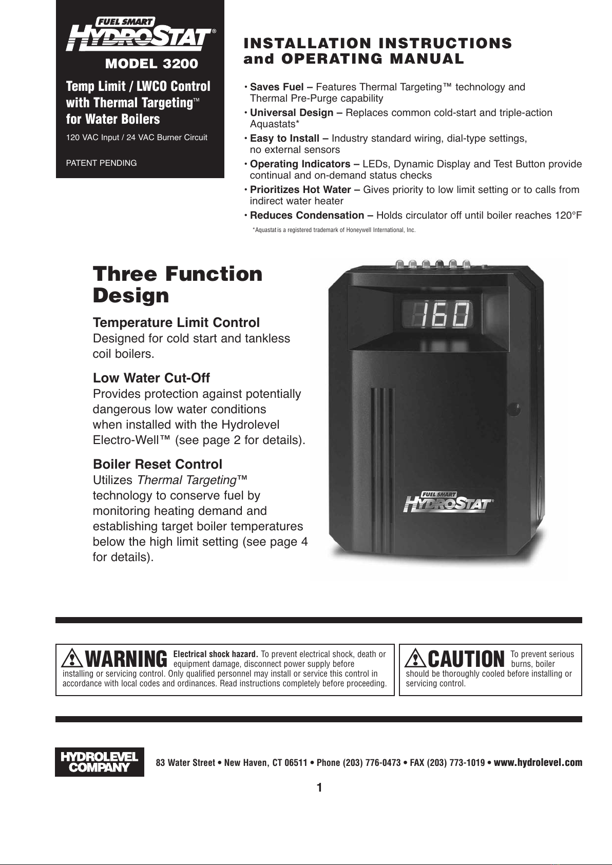
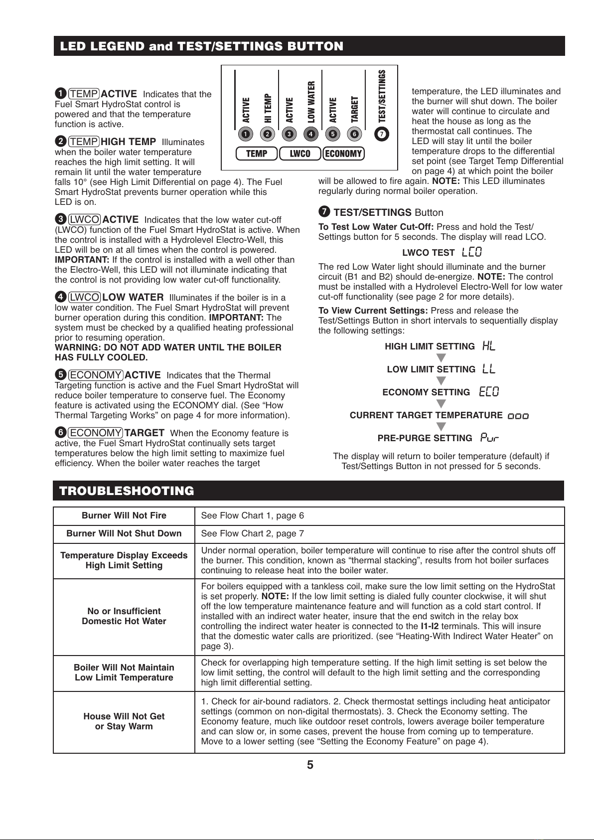
TEMP ACTIVE Indicates that the
Fuel Smart HydroStat control is
powered and that the temperature
function is active.
TEMP HIGH TEMP Illuminates
when the boiler water temperature
reaches the high limit setting. It will
remain lit until the water temperature
falls 10° (see High Limit Differential on page 4). The Fuel
Smart HydroStat prevents burner operation while this
LED is on.
LWCO ACTIVE Indicates that the low water cut-off
(LWCO) function of the Fuel Smart HydroStat is active. When
the control is installed with a Hydrolevel Electro-Well, this
LED will be on at all times when the control is powered.
IMPORTANT: If the control is installed with a well other than
the Electro-Well, this LED will not illuminate indicating that
the control is not providing low water cut-off functionality.
LWCO LOW WATER Illuminates if the boiler is in a
low water condition. The Fuel Smart HydroStat will prevent
burner operation during this condition. IMPORTANT: The
system must be checked by a qualified heating professional
prior to resuming operation.
WARNING: DO NOT ADD WATER UNTIL THE BOILER
HA FULLY COOLED.
ECONOMY ACTIVE Indicates that the Thermal
Targeting function is active and the Fuel Smart HydroStat will
reduce boiler temperature to conserve fuel. The Economy
feature is activated using the ECONOMY dial. (See “How
Thermal Targeting Works” on page 4 for more information).
ECONOMY TARGET When the Economy feature is
active, the Fuel Smart HydroStat continually sets target
temperatures below the high limit setting to maximize fuel
efficiency. When the boiler water reaches the target
temperature, the LED illuminates and
the burner will shut down. The boiler
water will continue to circulate and
heat the house as long as the
thermostat call continues. The
LED will stay lit until the boiler
temperature drops to the differential
set point (see Target Temp Differential
on page 4) at which point the boiler
will be allowed to fire again. NOTE: This LED illuminates
regularly during normal boiler operation.
TE T/ ETTING Button
To Test Low Water Cut-Off: Press and hold the Test/
Settings button for 5 seconds. The display will read LCO.
LWCO TE T 00
The red Low Water light should illuminate and the burner
circuit (B1 and B2) should de-energize. NOTE: The control
must be installed with a Hydrolevel Electro-Well for low water
cut-off functionality (see page 2 for more details).
To View Current ettings: Press and release the
Test/Settings Button in short intervals to sequentially display
the following settings:
HIGH LIMIT ETTING 00
LOW LIMIT ETTING 00
ECONOMY ETTING 000
CURRENT TARGET TEMPERATURE
PRE-PURGE ETTING 000
The display will return to boiler temperature (default) if
Test/Settings Button in not pressed for 5 seconds.
LED LEGEND and TEST/SETTINGS BUTTON

6
NO
YE NO
Is the
hermostat
( - ) Calling
for Heat?
Is here
24 VAC
Between B1
and B2?
NO
Is the
Domestic Water
(I1-I2) Calling for
Heat?
NO
Is the
Low Limit Dial
Set to OFF?
YE
NO
YE
Is the
Red LED
(LOW WA ER)
On?
he Control is
Sensing
Low Water.
CAU ION – ALWAYS ALLOW A BOILER O COOL BEFORE ADDING WA ER
he burner will not fire until the low water condition is satisfied.
Check that the system is filled with water.
Check that the sensor is inserted correctly into well.
Note: he use of heat-conductive grease may interfere with the
contact between the spring clip and the copper well tube.
Check that the control is tightly clamped to the well.
Is the
Yellow LED
(HI EMP)
On?
he Control is
Sensing High
emperature.
If both the red and yellow LEDs are off and
there is a call to fire the burner, there will be
24 VAC on terminals B1 and B2.
If 24 VAC is not present, the control should
be replaced.
HydroStat is supplying 24 VAC to the burner circuit.
Recheck wiring and operation of burner and other limit controls.
he Control
is Operating
Properly.
Replace
Control
he burner will not fire until the boiler water has dropped to the
high limit differential set-point (10° below high limit setting).
Check that the high temperature setting is correct.
Troubleshooting Flow Chart 1 – Burner Will Not Fire
YE
YE
NO
Is the
Yellow LED
( ARGE )
On?
he Boiler has
Reached the
arget
emperature.
When the ECONOMY function is active, the control monitors heating
demand and establishes arget boiler temperatures below the high
limit setting to conserve fuel (see “How hermal argeting Works”
on page 4). he burner will not fire until the boiler temperature
drops to the arget emp Differential (see “Differentials” on page 4).
YE
NO
Is the
Green LED
( EMP AC IVE)
On?
he Control is
Not Powered.
he emp Active LED will be on at all times when the control is
powered.
Check for 120 VAC on terminals L1 and L2.
YE
NO
When the low temperature
setting is set to OFF, the
HydroStat will act as a cold
start control. he burner
will not fire unless there is
a call from the thermostat
( - ) or the indirect water
heater (I1-I2).
Set thermostat to call
for heat. Burner should
fire.
If the boiler has a tank-
less coil, set the Low
emperature Limit to
maintain temperature.
YE

7
YE
Recheck
Wiring.
Replace
Control.
When there is no call to fire the burner, the voltage
should be 0 volts between B1 and B2.
Make sure the burner is wired to B1.
YE
NO
Is the
Low Limit Dial
Set to OFF?
Is there
24 VAC between
B1 and B2?
NO
Is the
hermostat
( - ) Calling
for Heat?
YE
YE
Is the
Domestic Water
(I1-I2) Calling for
Heat?
NO
NO
Is the
Red LED
(LOW WA ER)
On?
he Control is
Sensing
Low Water. WARNING!
URN OFF POWER O BURNER IMMEDIA ELY!
CAU ION – ALWAYS ALLOW A BOILER O FULLY COOL
BEFORE ADDING WA ER.
Recheck wiring. Make sure that burner is wired to
B1. Burner should never fire when red or yellow
LED is lit.
Is either
Yellow LED
On?
he Control has
Reached arget
or High Limit
emperature.
he Control is
Operating
Normally.
he Control is
Operating
Normally.
he burner will continue to fire when there is a call
from the thermostat or external zone.
Check temperature display. When the Low Limit is
set, the HydroStat will fire the burner until the
temperature reaches the Low Limit Setting.
If there is no call for heat (from - , I1-I2 or Low
Limit), there should be 0 VAC between B1-B2.
If there is voltage between B1-B2, the control
should be replaced.
Troubleshooting Flow Chart 2 – Burner Will Not hut Down
YE
YE
NO
NO

8
83 Water Street • New Haven, CT 06511 • Phone (203) 776-0473 • FA (203) 773-1019 • www.hydrolevel.com
REMOTE MOUNTING KITS
MAINTENANCE
Remove the Electro-Well from the heating system every five years and clean any scale or sediment deposits from all parts that are
exposed to the boiler water. After cleaning, reinstall the well using pipe sealing compound. Teflon tape is not recommended.
Part No. Description
48-101 HydroStat Remote Mount Kit with 24" sensor
48-102 HydroStat Remote Mount Kit with 48" sensor
Part No. Description
48-103 HydroStat Remote Mount Kit with 10' sensor
48-104 HydroStat Remote Mount Kit with 20' sensor
SPECIFICATIONS FUEL SMART HYDROSTAT MODEL 3200
DIMENSIONSELECTRO WELLS
LIMITED MANUFACTURERʼ WARRANTY
We warrant products manufactured by Hydrolevel Company to be free from defects in
material and workmanship for a period of two years from the date of manufacture or
one year from the date of installation, whichever occurs first. In the event of any claim
under this warranty or otherwise with respect to our products which is made within
such period, we will, at our option, repair or replace such products or refund the pur-
chase price paid to us by you for such products. In no event shall Hydrolevel Company
be liable for any other loss or damage, whether direct, indirect, incidental or conse-
quential. his warranty is your EXCLUSIVE remedy and shall be IN PLACE OF any other
warranty or guarantee, express or implied, including, without limitation, any warranty
of MERCHAN ABILI Y or fitness for a particular purpose. his warranty may not be
assigned or transferred and any unauthorized transfer or assignment thereof shall be
void and of no force or effect.
Input voltage 120 VAC, 60 HZ
Burner contacts 30 VA@24 VAC
Circulator contacts 5.8 FLA, 34.8 LRA@120 VAC
Operating range – low limit Off or 110°F - 200°F
Operating range – high limit 100°F - 220°F
Table of contents
Popular Control Unit manuals by other brands

Rievtech
Rievtech x-Messenger Series user manual

Rockwell Automation
Rockwell Automation Allen-Bradley ControlLogix 1756-IB16ISOE user manual

Siemens
Siemens VGD4 series Operation Manual and Mounting Instructions

Cyber Power
Cyber Power BP72V60ART2U user manual

Afag
Afag LE-50 Series Translation of the Original Montage Instructions

Burkert
Burkert 3320 quick start

Siemens
Siemens ALD-2I installation instructions

MOGAS
MOGAS ASME Class 600 Installation, operation and maintenance manual

Lenze
Lenze E84DZEVBLANP Mounting instructions

Freescale Semiconductor
Freescale Semiconductor 56F826 user manual

System Sensor
System Sensor IM-10 Installation and maintenance instructions

T&S
T&S B-0509 Installation and maintenance instructions