5
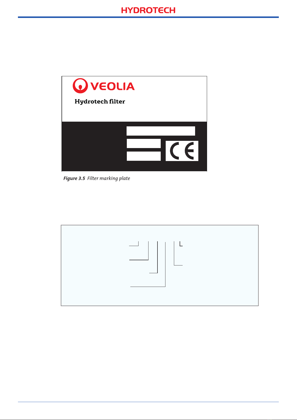
“Operation & Maintenance Manual”, “Discfilter HSF2600 series”
. SAFETY INSTRUCTIONS
2.
Hydrotech Discfilters in the HSF2600 series are designed for safe operation provided that they
are installed correctly and used in accordance with the enclosed instructions. The equipment
must be installed correctly and adapted in accordance with local regulations. The machine
equipment is intended for use by multiple operators. You must read the applicable chapters
in this manual prior to using the equipment or performing maintenance.
⊲ Pay attention to all warning symbols that appear in this manual.
If this information is ignored it may result in serious personal injury and/or damage to
equipment.
⊲ Assume all electrical equipment to be live.
⊲ Consider all hoses and pipes to be pressurised.
⊲ Before carrying out maintenance work, the main power switch (see Figure 2.3) must be
turned to the OFF (0) position and locked with a padlock.
⊲ Maintenance and service may only be performed by authorised personnel.
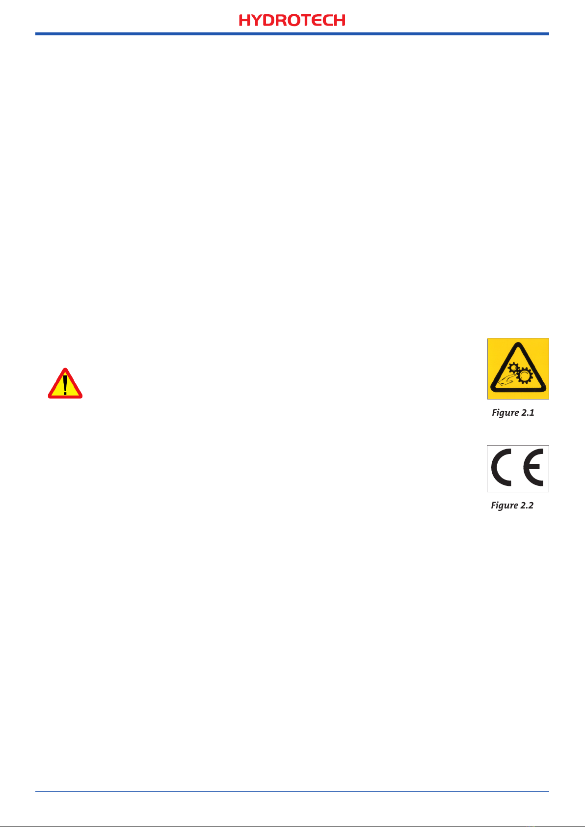
2.1 Warning symbols
Warning symbols are used in this manual to draw attention to potentially
dangerous situations:
Information that warns you of a potential risk of personal injury and/or
damage to equipment.
Warning labels (see Figure 2.1) are attached to the filter to warn personnel and
act as a reminder to keep hands and fingers away from the filter’s moving parts.
2.2 CE marking
This equipment is CE marked (see Figure 2.2), which guarantees that the
equipment is designed, manufactured and described in accordance with the
requirements set out in the EU Machinery Directive.
2.3 Conversion
The CE marking does not extend to any components that are not approved by Hydrotech AB
and that are used in conversion/reconstruction of the equipment.
The warning symbols and CE marking must be attached in such a way that they are fully visible. If
any part of the equipment with a warning symbol is replaced, a new symbol must be attached in
the same position. Damaged symbols and CE markings must be replaced immediately.
2.4 Personnel requirements
In order to avoid personal injury and damage to the equipment, service and maintenance
may only be carried out by personnel that have been trained to use the equipment and are
conversant in local regulations. Service and maintenance personnel may only handle those
parts of the equipment they have been trained for.
The operator may need to work inside the safety barrier and in the safety zone during main-
tenance and set-up before operation.