Hydrovane V04 PUAS Series User manual

Parts List & Service Manual
V04 Models (PUAS, PURS, PUTS)
Stationary Air Compressors
ST16191-00A-07/2012


Contents
1.0 Introduction 1
1.1 Support .....................................1
1.2 Product Development..............................1
1.3 Quality Standards................................1
1.4 Model Range ..................................1
1.5 Product Terminology ..............................1
1.6 Warnings, Cautions and Notes .........................1
1.7 Key to Symbols Used..............................1
1.8 Torque Settings .................................1
1.9 Service Kits ..................................½
2.0 Testing and Adjustments 3
2.1 Introduction ...................................3
2.2 Oil Temperature ................................3
2.3 Air Output ...................................3
2.4 Leakage Check ................................3
2.5 Minimum Pressure Valve ............................3
2.6 Safety Valve Lift Pressure ...........................3
2.7 Pressure Control Valve .............................3
2.8 Over-temperature Control Unit. .......................... ......4
3.0 Servicing 5
3.1 Introduction .......................................... ......5
3.2 Minimum Pressure Valve ............................5
3.3 Pressure Control Valve .............................5
3.4 Safety valve .......................................... ......5
3.5 Oil separator, Oil return valve ............................ ......5
3.6 Intake cover and Valve ................................. ......6
3.7 Oil Seal .....................................6
4.0 V04 Parts List 7
4.1 Intake Cover ......................................... ......8
4.2 Solenoid Valve ........................................ ......10
4.3 Oil Separator, Intake End Cover .......................... ......12
4.4 Rotor Stator Unit, Oil Chamber ........................... ......16
4.5 Oil Cooler, Bell Housing................................. ......20
4.6 Drive Motor, Receiver (PURS) ........................... ......22
4.7 Drive Motor, Tripod (PUAS).............................. ......26
4.8 Cooler, Pipework (PUAS) ............................... ......30
4.9 Aftercooler (PUARS) ................................... ......32
4.10 Membrane Dryer (PURDS) ............................. ......34
Contents hydrovane
ST16191-00A

Contents
5.0 V04 Starters
5.1 Starter 4.0kW 400V 3PH 50HZ DOL (PURS) ................ ......36
Continuous Run (200 Builds/MK3 Units)
5.2 Starter 4.0kW 400V 3 PH 50HZ DOL (PUAS)................ ......38
Continuous Run (200 Builds/MK3 Units)
5.3 Starter 220V 50HZ DOL ................................ ......40
Continuous Run/Stop Start (110 Builds/MK2 Units)
5.4 Pressure Switch Starter ................................. ......42
Auto/Manual Pressure Switch Control (210 Builds/MK3 Units)
5.5 Pressure Switch Starter ................................. ......44
Stop/Start (200 Builds/MK3 Units)
5.6 Starter 4.0kW 400V 3PH 50Hz SD (PUAS).................. ......46
Stop/Start (110 Builds/MK2 Units
5.7 Pressure Switch Control Unit ............................ ......48
Stop/Start (110 Builds/MK2 Units)
ST16191-00A
hydrovane Contents

1.1 Support
This publication contains parts lists and service information please
read it carefully before you attempt to service or carry-out
adjustments on the compressor.
This manual should be used in conjunction with the User Handbook.
Note: If you need any specialist help or service, please contact your
hydrovane distributor quoting the MODEL, TYPE and SERIAL
NUMBER.
1.2 Product Development
Hydrovane adopt apolicy of continual product Improvement.
Information in this handbook, whilst fully up to date when issued, may
be subject to change without notice.
1.3 Quality Standards
Hydrovane Quality Management Systems are approved to BS EN
ISO 9001.
Gardner Denver Ltd
Claybrook Drive
Washford Industrial Estate
Redditch
Worcestershire B98 ODS
United Kingdom
Telephone (01527) 525522
Fax:(01527) 521140
Web:www.hydrovane.co.uk
www.hydrovane@compair.com
www.compair.com
E-mail:sales@compair.com
1.4 Model Range
This handbook relates to all V04 50/60 Hz compressors, model
types:
504PUAS07-3835S110, 504PUAS10-3835S110
504PUAS10-4135S110
504PUAS10-2235D110, 504PUAS07-4035D110
504PUAS10-4035D110
504PUAS07-4035D210, 504PUAS10-4035D210
504PURS10-4035D100, 504PURS10-4035D110
504PURS10-4035D200, 504PURS10-4035D210
504PRDS10-4035D200
1.5 Product Terminology:-
5, V Series type, Vane
04 kW motor
07, 10 Delivery pressure in bars (psi)
PURS Package Unit, Receiver and Starter
PUTS Package Unit, Tripod and Starter
PRDS Package Unit, Receiver, Dryer and Starter
24/40 Voltage
1/3 Single/Three phase
5, 6 50/60Hz
D, S Direct on Line, Star Delta
200, 400 Revision number
This publication refers to compressors with serial numbers
504-011524-1203 onwards (200 builds/MK3)
1.6 Warnings, Cautions and Notes
‘WARNING’ is used in the text of this handbook to identify specific
hazards which can cause injury or death.
‘CAUTION’ is used in the text of this handbook to identify incorrect
procedures which can cause damage to the compressor.
‘NOTE’ is used in the text of this handbook to draw attention to
specific points of importance.
1.7 Key to Symbols Used
Symbols that appear in this parts book have the following meanings
1.8 Torque Settings
Listed below are recommended torque settings.
Thread Size (mm)Setting (Nm)
6 15
8 35
10 60
12 95
16 160
42 400
Note: Torque settings and grease must be applied when indicated.
1.9 Service Kits
Only use genuine hydrovane parts and FLUID FORCE RED 2000 or
an APPROVED OIL, do not mix lubricants.
Note:Spare parts to be stored in original packaging and in adry
environment. Repaired or replacement units should be protected
against corrosion and mechanical damage during storage.
ST16191-00A Page 1
1.0 Introduction hydrovane
Torque Setting Nm.
Grease Required (Specification)
Loctite Required and Specification Number
Spanner Required (mm) A/F
Allen key Required (mm)
Lubricate With Sump Oil

Page 2ST16191-00A
1.0 Introduction hydrovane
Item Part Number Quantity Description Section Page Item
V04 Maintenance Kit KM52
157019 1 Air Filter 4.1 8 17
2 57029 1 Oil Separator Element 4.3 12 1
3 57060 1 Gasket 4.3 12 3
4 CZ9609 1 Bonded Seal G1/44.1 8 26
5 CZ9616 1 Bonded Seal G1/24.4 16 17
6 CZ9619 1 Bonded Seal G3/44.1 8 14
7 CZ9707 1 'O' Ring 4.1 8 12
8 CZ9831 1 'O' Ring 4.1 8 8
9 74595 'O' Ring 4.8 30 27
10 CZ9606 1 Bonded Seal G1/84.4 18 21
11 CZ9611 1 Bonded Seal 0.60 WHIT 4.4 18 33
V04 Top Up Kit KT53
1CZ53680 1 Seal Shaft 4.4 18 23
2 57016 1 Gasket 4.3 12 22
3 57046 2 Cooler Gasket 4.5 20 4
4 57047 1 Lantern Gasket 4.4 16 15
5 72073 1 Oil Seal 504 4.4 18 23
6 32655 1 Valve Stem Sub-assembly 4.3 14 24
7 32970 1 Facing & Stem Assembly 4.1 8 10
8 57028 1 Coupling Spider 4.6 22 9
9 57053 1 Gasket 4.1 8 22
10 CZ58010 6 Copper Washer-M8 4.3 12 6
11 58013 1 M14 Copper Washer 4.4 18 33
12 58117 1 Sight Level Glass 4.4 16 18
13 58416 1 Gasket 4.4 16 7
14 58426 1 SIght Glass Clip 4.4 16 18
15 CZ9705 1 'O' Ring 4.3 14 28
16 MW5 1M5 Washer 4.3 14 32
17 CZ9606 1 Bonded Seal G1/84.4 18 21
18 CZ9751 8 'O' Ring 4.3 12 20
19 CZ9752 1 'O' Ring 4.3 12 20
20 CZ9754 1 'O' Ring 4.4 16 18
21 CZ9763 1 'O' Ring 4.3 14 25
22 9897 1 'O' Ring 4.3 12 11
23 75626 1 Coupling Element 4.6 22 9
24 CZ9619 1 Bonded Seal G3/44.4 16 19
25 CZ9609 3 Bonded Seal G1/44.4 18 28
26 57017-B 2 Stator Gasket 4.4 16 4
27 57017-C 2 Stator Gasket 4.4 16 4
28 57017-D 2 Stator Gasket 4.4 16 4
29 57017E 2 Stator Gasket 4.4 16 4
30 56391 1 Pressure Gauge 4.1 8 3
31 CZ9750 1 'O'Ring 4.3 12 20

2.1 Introduction
WARNING
READ HEALTH AND SAFETY PRECAUTIONS
BEFORE YOU START ANY SERVICE WORK.
Adjustment procedures shown must only be carried out by
authorised persons fully trained and competent in the maintenance
of hydrovane compressors.
If you are not able to carry out the work safely, contact your
hydrovane distributor.
2.2 Oil Temperature
Start the compressor and allow to run for 20 minutes in order to
attain its normal working temperature.
Average running temperature, taken by thermometer in the oil filler
thermal pocket should be approximately 60°C(140°F) above
ambient.
2.3 Air Output (Fig. 2.1)
Screw test nozzle 59634-06 (7 bar/102 psi) or 59634-07 (10 bar/145
psi) into compressor outlet.
Close outlet valve and start compressor (continuous run).
Open outlet valve fully, pressure on gauge should not fall below 6.5
bar/94 psi for a 7 bar machine or 9.5 bar/138 psi on a 10 bar/145 psi
machine.
2.4 Leakage Check
Examine all external seals, gaskets and pipe connections for air or
oil leakage, no leaks are permissible.
2.5 Minimum Pressure Valve (Fig. 2.2)
Close outlet valve and start compressor, open outlet valve fully to
atmosphere.
Check the gauge pressure reading.
When set correctly the gauge should show 5 bar (73 psi) and will
operate satisfactorily between 4 bar (58 psi) and 6 bar (87 psi).
2.6 Safety Valve Lift Pressure (Fig. 2.3) PURS
Safety valves are preset to lift as follows:
07 bar (102 psi) compressor = 08 bar (116 psi).
10 bar (145 psi) compressor = 11 bar (160 psi).
Should the safety valve be faulty it cannot be adjusted and must be
renewed as a complete unit.
2.7 Pressure Control Valve (Fig. 2.3)PUTS/PUAS
Close outlet valve and start compressor (continuous run).
Gauge should read either 7.5/109 psi for a 7 bar/192 psi machine or
10.5 bar/152 psi for a 10 bar/145 psi machine.
Should gauge read differently DO NOT attempt to adjust the valve,
renew as a complete unit.
Note the pressure setting written on valve when reordering.
ST16191-00A Page 3
2.0 Testing and Adjustments hydrovane
Fig 2.2 - Minimum Pressure Valve
Fig 2.3 - Pressure Control and Safety Valves
Fig 2.1 - Air Output

2.8 Over-temperature Control Unit. (Fig 2.4)
WARNING
THE FOLLOWING FAULT FINDING PROCEDURE
SHOULD BE CARRIED OUT BY QUALIFIED AND
COMPETENT PERSONS ONLY.
THIS PANEL CONTAINS POTENTIALLY LETHAL
VOLTAGES. UNDER NO CIRCUMSTANCES
SHOULD YOU ATTEMPT TO TOUCH ANYTHING
INSIDE THE CONTROL PANEL, OR ON THE
CONTROL PANEL DOOR UNLESS INSTRUCTED
TO DO SO IN THE FOLLOWING PROCEDURE.
Start compressor
Open the starter panel door
Unscrew terminal 38 and remove the connecting wire.
The compressor drive motor must stop immediately
Without re-setting the starter or disconnecting the mains supply to
the starter re-connect the circuit, terminal 38.
Reinstate the electrical control box cover and front panel
CAUTION
If the above sequence is not achieved then a fault may have
occurred which has damaged the OTC. The compressor must not
be operated until a replacement OTC has been fitted and the above
procedure repeated.
Reinstate all panels
Page 4ST16191-00A
hydrovane 2.0 Testing and Adjustments
Fig 2.4 - Over-temperature Control Unit

3.1 Introduction
WARNING !
READ HEALTH AND SAFETY PRECAUTIONS
BEFORE YOU START ANY SERVICE WORK.
SERVICING OF THE COMPRESSOR MUST ONLY
BE CARRIED-OUT BY AUTHORISED PERSONS
FULLY TRAINED AND COMPETENT IN THE
MAINTENANCE, MAINS ELECTRICAL SUPPLY
AND STARTER CONTROL EQUIPMENT OF
HYDROVANE COMPRESSORS. THEY MUST
FULLY UNDERSTAND AND ADOPT CORRECT
AND SAFE WORKING PRACTICES.
Routine servicing should be carried out as instructed in the User
Handbook, ensure genuine parts are available for the following
tasks.
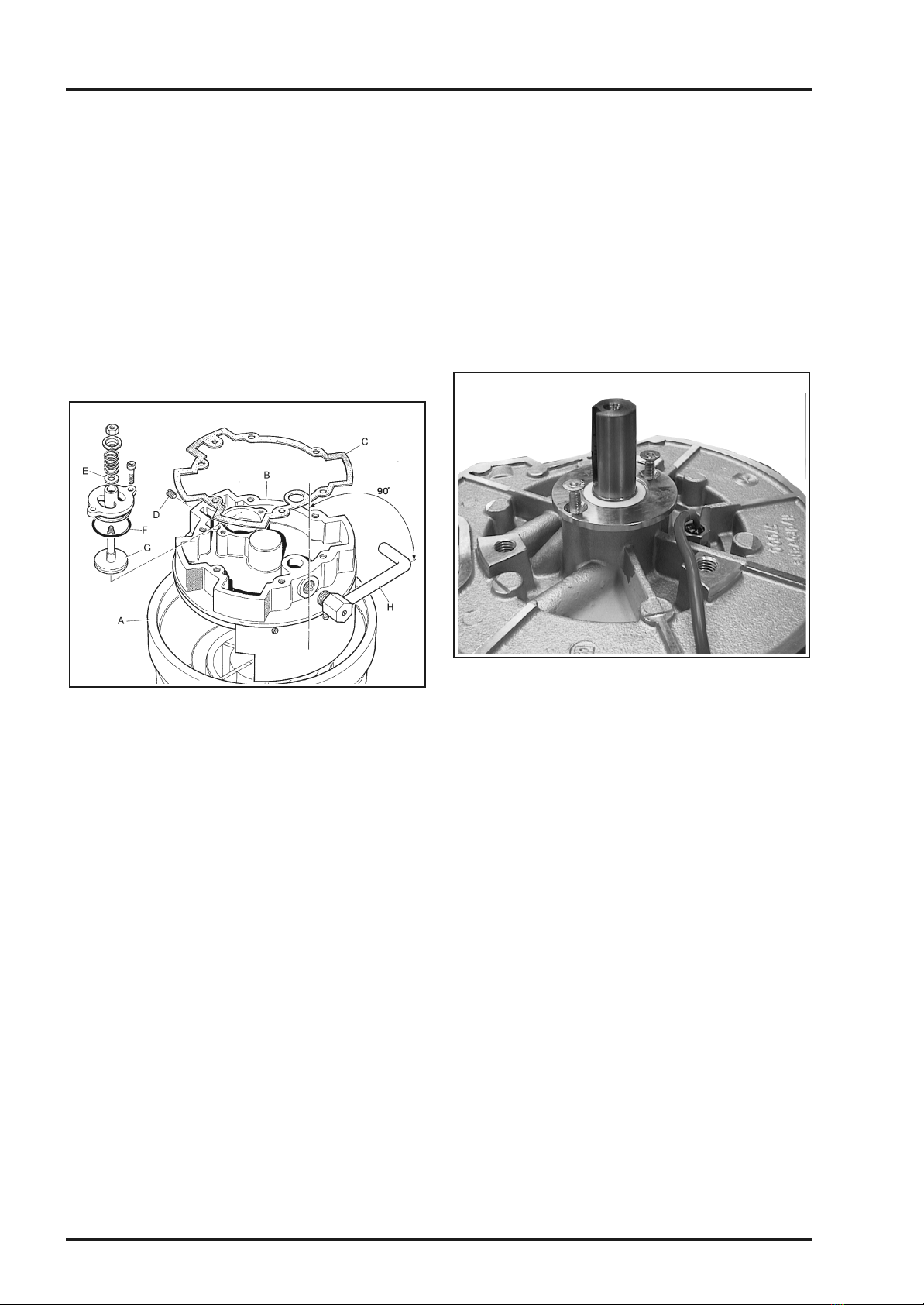
3.2 Minimum Pressure Valve (Fig 3.1)
Remove screws that retain the air filter cover to gain access to the
minimum pressure valve.
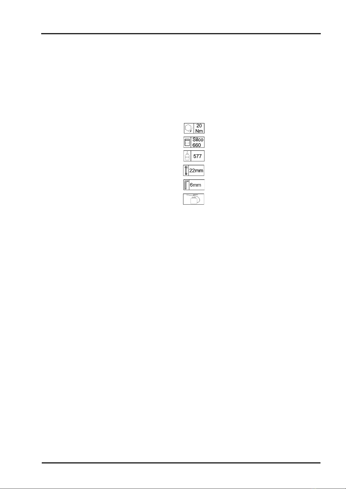
Renew bonded seal (A) and 'O' ring (B), apply silicon grease before
refitting.
Check piston ©) and valve (D) for wear or damage, renew if
necessary.
Clean filter (E) in white spirit or parafin, apply compressed air to
threaded end of filter, renew if it cannot be cleaned satisfactorily.
Testing of the minimum pressure valve is shown in Section 2.5.
3.3 Pressure Control Valve (Fig 3.2) PUTS/PUAS
Remove the screws that retain the valve cover plate.
Remove pressure control valves (F) and note settings, 7 or 10 bar
(100 psi or 145 psi), renew bonded seals (G)
Renew valves complete if found faulty, ensure new valves have the
same pressure rating as those removed. DO NOT attempt to adjust
or dismantle the valves
Testing of the pressure control valve is shown in Section 2.7
3.4 Safety Valve (Fig 3.2) PURS
Remove safety valve (H) renew bonded seal (G), replace valve if
found faulty, it cannot be dismantled or adjusted.
Testing of the safety valve is shown in Section 2.6
3.5 Oil Separator, Oil Return Valve (Fig 3.3)
Drain compressor oil, remove screws that retain the air filter cover.
Remove end cover (A) note its position relative to the separator
housing (F) for correct location on assembly, renew 'O' ring (B).
Unscrew oil separator ©) and examine, if contaminated or faulty, it
must be renewed, it cannot be cleaned
Renew the oil separator 'O' ring (D) and gasket (E)
Remove the separator housing (F) noting its position relative to the
oil chamber for correct location on assembly.
Renew 'O' ring (G) on separator housing (F), check restrictor plug
(H) in housing to ensure its orifice is clear.
Renew washer (J) on oil return valve (K), renew if contaminated,
replace washers (L) on housing bolts on re-assembly.
Refill compressor with FLUID FORCE RED 2000 or an APPROVED
OIL when assembly is complete.
ST16191-00A Page 5
3.0 Servicing hydrovane
Fig 3.1 - Minimum Pressure Valve
Fig 3.2 - Pressure Control and Safety Valves
Fig 3.3 - Oil Separator, Oil Return Valve

3.6 Intake Cover and Valve (Fig 3.4)
Drain compressor oil, remove compressor from motor, remove
separator end cover and housing.
Remove the intake end cover (B), note position with oil chamber (A),
discard the gasket ©),
Inspect the inner face of the intake end cover and its white metal
bearing for damage or score marks, renew if necessary.
Check orifice in restrictor plug (D) is completely clear, renew damper
(E) on inlet valve and 'O' ring (F).
Examine valve stem (G), renew if stem or sealing face are
damaged.
If discharge pipe assembly (H) has been removed, on re-assembly it
must be positioned at 90 degrees to the machine axis. The pipe
assembly must be fitted using loctite 577 on the screw threads.
3.7 Oil Seal (Fig 3.5)
Drain compressor oil, remove compressor from motor, remove drive
coupling, lantern and cooler.
Remove screws from seal housing, pull oil seal assembly out of oil
chamber.
Clean seal housing and remove burrs on oil chamber, refit new seal
using applicator (Service Tool S101), remove applicator, refit fixing
screws.
Fit drive coupling in correct position, renew ‘O’ rings on cooler
couplings.
Reassemble and refill compressor with FLUID FORCE RED 2000 or
an APPROVED OIL when assembly is complete.
hydrovane 3.0 Servicing
Page 6
Fig 3.5 - Oil Seal
Fig 3.4 - Intake Cover and Valve

Parts List and Service Manual
ST16191-00A Page 7
4.0 V04 Compressor Parts hydrovane

Air Intake Filter
On PUTS models, first remove the outlet valve or delivery pipework.
Remove screws (1) and cover (2), completely on PUTS models or
slide it over the air delivery pipe on PUAS or PURS models.
Remove the filter (17) and filter support (19), wash the filter in soap
and water, leave to dry before refitting. Renew the filter if it cannot be
cleaned satisfactorily.
Clean inside of cover (2) and filter support (19) prior to refitting,
ensure filter and support are correctly located and/or secured in clip
(Item 8 Page 12)
Minimum Pressure Valve
Renew bonded seal (14) and 'O' ring (12), apply silicon grease before
refitting.
Check piston (11) and valve (10) for wear or damage, renew if
necessary, test the valve as detailed in Section 2.5
Pressure Control Valves (PUTS/PUAS)
Remove the valves (25) and note the settings 7 or 10 bar (101 or 145
psi) marked on them, renew bonded seals (26)
Renew valves complete if found faulty, ensure new valves have the
same pressure rating as those removed. DO NOT attempt to adjust
or dismantle the valves
Safety Valve (PURS)
Remove safety valve (23) renew bonded seal (26), replace valve if
found faulty, it cannot be dismantled or adjusted.
Page 8ST16191-00A
4.1 Intake Cover hydrovane
Item Part No Description Kit Quantity
All PUAS PURS
1MS2108-12 M8 x 12 Panhead Screw 2
2 58444 Air Filter Cover 1
356391 Pressure Gauge KT53 1
456908 Adaptor 1
5 MS708-30 M8 x 30 Socket Head Screw 6
6 59425-01 Taper Plug 1/8" BSP 1
7a 32839 Separator End Cover Assembly 1
7b 57010 Separator End Cover 1
8 CZ9831 ‘O’ Ring KM52 1
958455 Separator Baffle 1
10 32970 Facing and Stem Assembly (MPV) KT53 1
11 59238 MPV Piston 1
12 CZ9707 ‘O’ Ring KM52 1
13 59241 MPV Spring 1
14 CZ9619 Bonded Seal G3/4 KM52 1
15 59237 MPV Body 1
16 32662 Filter and Plug Sub Assembly 1
17 57019 Air Filter KM52 1
18 56426 4-40 x ¼" Pozipan Taptite 2
19 57044 Air Filter Support 1
20 MS706-16 M6 x 16 Socket Head Screw 4
21 57052 Valve Cover 1
22 57053 Gasket KT53 1
23 56289 Safety Valve 1
24 59425-02 Taper Plug ¼" BSP 1
25a 57302 Pressure Control Valve (7bar) PUTS 2
25a 57443 Pressure Control Valve (10 bar) PUTS 2
26 CZ9609 Bonded seal G1/4 KM52 21

ST16191-00A Page 9
hydrovane 4.1 Intake Cover
Fig 4A - Intake Cover

Solenoid Valve (PUAS)
The solenoid valve (13) provides a controlled vent to intake on
stopping.
32694 cable assembly is used with CZ35150 and 35155 pressure
switch control units.
Blowdown Filter (PUAS)
Clean filter (1) using white spirit or paraffin, check/clean the threaded
end of dirt or debris.
Renew the filter if it cannot be cleaned satisfactorily
Page 10 ST16191-00A
4.2 Solenoid Valve hydrovane
Item Part No Description Kit Quantity
All PUAS PURS
34243 Solenoid valve Assembly 1
1 1846 Oil Return Valve Assembly 1
2W5-2 Sealing Washer G1/4 1
3 1730 Orifice Plate 1
473213 Stud Adaptor G1/4-6mm, Push in 1
5 73282 Equal Tee Adaptor 6mm 1
6 ST214671 Tube 6mm Nylon A/R
7CZ52930 Stud Elbow 6mm - 1/8" BSP-6mm 1
873215 Push in elbow R1/8" - 6mm 2
9 MS104-30 M4 x 30 Long Hex Hd Screw 2
10 MN104 M4 Hex Nut 2
11 MWG4 M4 Spring Washer 2
12 73622 Solenoid Mounting Bracket 1
13 73841 Solenoid Valve 24V NO 1
A 32694 Cable Assembly 1

ST16191-00A Page 11
hydrovane 4.2 Solenoid Valve
Fig 4B - Solenoid Valve

Oil Separator
Drain compressor oil.
Remove outer end cover (Item 7 page 8) note its position relative to
the separator housing (7) for correct location on assembly, renew 'O'
ring (11).
Unscrew oil separator (1) and examine, if found to be contaminated
or faulty, it must be renewed, it cannot be cleaned
Renew the oil separator 'O' ring (2) and gasket (3)
Remove the separator housing (7) noting its position relative to the oil
chamber (Item 20 page 18) for correct location on assembly.
Renew 'O' ring (11) on separator housing (7), check restrictor plug
(10) in housing to ensure its orifice is clear.
Renew copper washer (12) on oil return valve (13), renew the oil
return valve if contaminated, replace copper washers (6) on housing
bolts (5) on re-assembly.
Refill compressor with FLUID FORCE RED 2000 or an APPROVED
OIL when assembly is complete.
Page 12 ST16191-00A
4.3 Oil Separator, Intake End Cover hydrovane
Item Part No Description Kit Quantity
All PUAS PURS
157029 Oil Separator Element including:-KM52 1
2CZ9799 ‘O’ Ring 1
3 57060 Gasket KM52 1
456275 Separator Stud 1
5 57031 Oil Chamber Bolts 6
6 CZ58010 Copper Washer KT53 6
7a CZ32555 Separator Assembly including;- 1
7b 57001 Separator Case 1
8 58408 Retainer Spring 1
9 56426 4-40 x ¼" Pozipan Taptite 2
10 58358 Restrictor Screw 1
11 CZ9897 ‘O’ Ring KT53 1
12 58327 Folded Copper Washer ¼" BSP 1
13 32386 Oil Return Valve Assembly 1
14 CZ57058 Primary Cowl Outer 1
15 PE567-C6 6G x3/8" Pozipa BSelf Tap Screw 4
16 57071 Elbow R1/2-12mm 1
17 MG1706-10 M6 x10 Socket Set Screw TUFlock 1
18 57042 Discharge Pipe 1
19a 32641 Intake End Cover Assembly 1
19b CZ32554 End Cover Assembly 1
19c 57003 End Cover 1
20 CZ9750 'O' ring KT53 1
21 59262 Restrictor Screw 1
22 57016 Gasket KT53 1

ST16191-00A Page 13
hydrovane 4.3 Oil Separator, Intake End Cover
Fig 4C -Oil Separator, Intake End Cover

Intake End Cover
Drain compressor oil, remove compressor from motor.
Remove the intake end cover (19) and discard the gasket (22),
Inspect the inner face of the intake end cover and its white metal
bearing for damage or score marks, renew if necessary.
Check orifice in restrictor (21) is completely clear, renew damper (28)
on inlet valve and 'O' ring (25).
Examine valve stem (24), renew if stem or sealing face are damaged.
If discharge pipe assembly (18) has been removed, on re-assembly it
must be positioned at 90 degrees to the machine axis. The pipe
assembly must be fitted using loctite 577 on the screw threads.
Page 14 ST16191-00A
4.3 Oil Separator, Intake End Cover hydrovane
Item Part No Description Kit Quantity
All PUAS PURS
23 34249 Intake Valve Assembly including:- 1
24 32655 Valve Stem Sub-Assembly KT53 1
25 CZ9763 'O' Ring KT53 1
26 57011 Valve Body 1
27a MS706-16 M6 x16 Socket Head Screw 2
27b MWG6 M6 Spring washer 2
28 CZ9705 'O Ring KT53 1
29 58440 Spring 1
30 58449 Spring Support Plate 1
31 3656 M5 Philidas Nut 1
32 MW5 M5 Plain Washer 1

ST16191-00A Page 15
hydrovane 4.3 Oil Separator, Intake End Cover
Fig 4C -Oil Separator, Intake End Cover

Rotor Stator Unit - Dismantling
Drain compressor oil, remove compressor from motor.
Remove compressor coupling (Item 7 page 22) and (Item 2 page 26).
Remove intake end cover (Item 19 page 12), stand the oil chamber
(20) vertically on wooden blocks.
Remove stator (6), note positions and thickness of shims (4) at each
end of stator.
Retain blades (2) in position in the rotor slots (1) using elastic bands,
remove rotor.
If blades (2) are to be re-used, they must be removed from their slots
and marked with a felt tip pen (NOT SCRATCHED) so that each
blade can be re-fitted in its original position.
Blades (2) and rotor slots (1) must be perfectly clean before
assembly.
Blades must be fitted with their rounded edge outwards and with their
slotted faces orientated as shown in the illustration, never reverse
blades in their slots.
Examine the oil chamber (20) end face and white metal bearing for
wear or damage, renew if necessary.
Examine stator (6) for damage, ensure the cutaway is clearly defined
by two straight lines running the length of the bore, renew if
necessary
Ensure stator bore and end faces are free from debris and perfectly
clean before assembly, tension pin (5) must be in position before
assembly.
Discharge Manifold
Remove screws (9) that secure manifold (8), renew gasket (7).
Ensure that the manifold discharge port is facing the drive end of the
stator (6) on assembly.
For example, when looking on the discharge manifold port the oil
relief valves should be on the left.
Page 16 ST16191-00A
4.4 Rotor Stator Unit, Oil Chamber hydrovane
Item Part No Description Kit Quantity
All PUAS PURS
157007 Rotor 1
2a 57009 Blades 6
2b 70498 Blades (7 bar 60 Hz) 6
3 57037 Drive Key 1
4a 57017A Stator Gasket, purple 0.03mm (0.0015") KT53 1
4b 57017B Stator Gasket, red 0.04mm (0.0015") KT53 1
4c 57017C Stator Gasket, blue trans 0.05mm (0.002") KT53 1
4d 57017D Stator Gasket, green 0.08mm (0.003") KT53 1
557416 M6 x14 Tension Pin 2
6a 32595 Stator Assembly (7Bar)1
6b 32596 Stator Assembly (10 Bar)1
6c 32597 Stator Assembly (7Bar 60 Hz) 1
7 58416 Gasket KT53 1
857054 Outlet Manifold 1
9a MS706-20 M6 x20 Socket Head Screw 4
9b MWG6 M6 Spring washer (not shown) 4
10 FS702-3 4BA x 3/8" Socket Head Screw 2
11 AGS203B 4BA Lock washer 2
12 CZ56586 Valve Support 2
13 56302 Valve Plate 2
14 57027 M3 x10 Tension Pin 4
15 57047 Lantern Gasket KT53 1
16 59389 Filler Plug ½" BSP 1
17 CZ9616 Bonded Seal G1/2KT53 1
18 32625 Sight Level Glass Assembly KT 53 1
19 CZ9619 Bonded Seal G3/41
This manual suits for next models
15
Table of contents
Other Hydrovane Air Compressor manuals
Popular Air Compressor manuals by other brands

Parkside
Parkside PKZ 180 B2 Translation of the original instructions

ALITA
ALITA AL-30 Operation & maintenance manual

Sullair
Sullair 3000P user manual

Campbell Hausfeld
Campbell Hausfeld FP2601 Operating instructions and parts manual

Husky
Husky H15123TK Operator's manual

Emerson
Emerson Copeland ZR16 manual