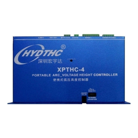
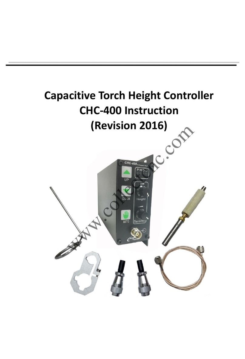
Hydthc CHC-1000S User manual

CHC-1000S
Capacitive Height Controller
User Manual
V3.0
宏宇达数控 & 弘宇达智能
www.hydcnc.com

Catalogue
1.Brief introduction .................................................................................................................................3
1.1 Introduction................................................................................................................................3
1.2 Performance Description...........................................................................................................4
2. Diagram introduction.............................................................................................................................5
2.1 components...............................................................................................................................5
2.2 installation size..........................................................................................................................6
2.2.1 main controller ..............................................................................................................6
2.2.2 preamplifier...................................................................................................................7
2.3 interface specification................................................................................................................8
2.3.1 interface layout.............................................................................................................8
2.3.2 power interface .............................................................................................................8
2.3.3 input and output interface..............................................................................................9
2.3.4 sensor interface ..........................................................................................................11
2.3.5 Application ..................................................................................................................12
3. Operation Introduce............................................................................................................................13
3.1 keyboard introduction..............................................................................................................13
3.2 Home page..............................................................................................................................13
3.3 Menu structure.........................................................................................................................14
3.4 Calibration interface.................................................................................................................15
3.5 Test menu ...............................................................................................................................16
3.6 Parameter menu......................................................................................................................16
3.6.1 Control parameters.....................................................................................................17
3.6.2 Advanced parameters.................................................................................................18
3.6.3 Alarm parameter .........................................................................................................19
3.6.4 Network parameter .....................................................................................................20
3.7 System parameters .................................................................................................................21
3.7.1 version information......................................................................................................21
3.7.2 Warning.......................................................................................................................22
3.7.3 Restart ........................................................................................................................22
3.7.4 Parameters Setting.....................................................................................................22
4. warning introduction............................................................................................................................23
4.1 warning introduce and reason.................................................................................................23
5.test introduction....................................................................................................................................25
5.1 Manual reference point (16 points) calibration........................................................................25
5.2 Automatic reference point (16 points) calibration....................................................................25
5.3 Adjust system and control parameters to optimize PID..........................................................27
6. Wiring introduction..............................................................................................................................28

宏宇达数控 & 弘宇达智能
地址:深圳市南山区中山园路 1001 号E4-6C(TCL 国际 E城)
TEL:0755-26625800 FAX:0755-26729960 -3-
1.Brief introduction
1.1 Introduction
CHC-1000S capacitance height controller(Hereinafter referred to as CHC-1000S). In
the laser cutting process, the distance between the nozzle and the surface of the
workpiece is not constant due to factors such as uneven workpiece and cutting high-
pressure air jet, which will have a negative effect on the cutting effect and may even
crash the nozzle. CHC-1000S can keep the distance between the nozzle and the
workpiece surface constant during high-speed laser cutting, protect the nozzle from
colliding with the workpiece, and greatly improve the cutting effect. The capacitance
sensor on the cutting head can detect the distance from the nozzle to the surface of the
workpiece, and send it to the adjustment box for processing through the preamplifier. The
output signal is sent to the servo controller to control the Z axis.
CHC-1000S can be used as a controller to output the voltage, or as a distance
measurement system to output the distance signal, it depends on the selected mode:
sensor control mode or distance measurement system mode.
1-1. system diagram
1 workpiece 4 electrode cable
2 sensor 5 preamplifier
3 laser head 6sensor cable

宏宇达数控 & 弘宇达智能
地址:深圳市南山区中山园路 1001 号E4-6C(TCL 国际 E城)
TEL:0755-26625800 FAX:0755-26729960 -4-
1.2 Performance Description
Sampling rate: 1000 times per second.
Static measurement accuracy: 0.001mm.
Following range: 0-25mm.
The signal will not decay with strong capacity of resisting when the length
of signal transmission cable is up to 100m.
Support network communications and U disk online update.
Supports shake suppression function, can effectively suppress shaking
caused by blowing and scumming.
Adapt to any cutting head and nozzle.
Support alarm while hitting the board and beyond the edge.
Supports 1 point, 2 point and 16 point capacitance calibration, which
supports the display of the calibration curve.
Support capacitor real-time calibration, which can effectively solve the
influence of temperature and other factors on the capacitive sensor.
16-bit DA output, output voltage (±10V) signal in sensor control mode, or
linear height signal in the distance measurement mode output voltage (0-
10V), 1000 update cycles per second.
14-bit AD input, detecting external analog voltage signal (0V-10V) to adjust
the static distance in real time.
Support oscilloscope function to detect capacitance and height changing in
real time.
Support oscilloscope function, which can view AD/DA changes anytime.
Support EtherCAT bus communication. (optional)

宏宇达数控 & 弘宇达智能
地址:深圳市南山区中山园路 1001 号E4-6C(TCL 国际 E城)
TEL:0755-26625800 FAX:0755-26729960 -5-
2. Diagram introduction
2.1 Components
The capacitance height control system consists of CHC-1000S controller, preamplifier,
cable etc, as shown below:
name
qty
standard
optional
main controller
1
CHC-1000S
preamplifier
1
CHC_AMP
RF cable
1
SPC-140(140mm)
SPC-180(180mm)
Sensor cable
1
STC-10(10m)
STC-15(15m)
connector(male)
1
DB25(M)
manual
Please visit our website to download.

宏宇达数控 & 弘宇达智能
地址:深圳市南山区中山园路 1001 号E4-6C(TCL 国际 E城)
TEL:0755-26625800 FAX:0755-26729960 -6-
2.2 Installation size
2.2.1 Main controller
Main controller as below:
front
side

宏宇达数控 & 弘宇达智能
地址:深圳市南山区中山园路 1001 号E4-6C(TCL 国际 E城)
TEL:0755-26625800 FAX:0755-26729960 -7-
2.2.2 Preamplifier
The preamplifier size as below:
Old
New

宏宇达数控 & 弘宇达智能
地址:深圳市南山区中山园路 1001 号E4-6C(TCL 国际 E城)
TEL:0755-26625800 FAX:0755-26729960 -8-
2.3 Interface specification
2.3.1 Interface layout
2.3.2 Power interface
The outer box of the machine is the negative pole of the capacitor to be tested. In
order to ensure the stable operation of the measuring circuit, the “PE foot” of the power
interface must be connected to the machine box (ie, it is well connected to the machine
box), and the box of the preamplifier must also be connected to the box of the machine.
The specific indicator is that the DC impedance is always less than 10 ohms, otherwise
the actual follow-up effect may be poor.

宏宇达数控 & 弘宇达智能
地址:深圳市南山区中山园路 1001 号E4-6C(TCL 国际 E城)
TEL:0755-26625800 FAX:0755-26729960 -9-
2.3.3 Input and output interface
25-pin female input and output interface
pin
signal definition
pin
signal definition
1
24V (power input)
14
0V (GND)
2
OUT1(signal output)
15
IN1 (signal input)
3
OUT2(signal output)
16
IN2 (signal input)
4
OUT3(signal output)
17
IN3 (signal input)
5
OUT4(signal output)
18
IN4 (signal input)
6
OUT5 (signal output)
19
IN5 (signal input)
7
OUT6 (signal output)
20
IN6 (signal input)
8
(reserved interface)
21
IN7 (signal input)
9
(reserved interface)
22
IN8 (signal input)
10
CAN-H (CAN bus communication
interface)
23
CAN-L (CAN bus communication
interface)
11
AD+ (0-10V positive input interface)
24
AD- (0-10V negative input
interface)
12
DA+ (±10V positive output interface)
25
DA- (±10Vnegative output
interface)
13
0V (GND)

宏宇达数控 & 弘宇达智能
地址:深圳市南山区中山园路 1001 号E4-6C(TCL 国际 E城)
TEL:0755-26625800 FAX:0755-26729960 -10-
interf
ace
defi
nitio
n
I/O
Signal name
voltag
e
remark
Digital
IN1
A3
I
CAL.REQUEST/
SET RANGE/
SET RANGE
Reference point
calibration
Two point calibration,
100%MBEW
One point calibration,
100%MBEW
Calibration start signal
IN2
A4
I
SELECT
CHAR.BIT0
Two point calibration
10%MBEW
Select the calibration
characteristic curve
IN3
A5
SELECT
CHAR.BIT1
IN4
A6
SELECT
CHAR.BIT2
IN5
A7
STROBE
Calibration signal(Teach
mode)
IN6
A8
I
Zn1-4 BIT0
normal mode
Selection interval
(Zn1-4)
IN7
A9
Zn1-4 BIT1
IN8
B1
I
CHECK
Real-time calibration
signal
OUT1
A10
O
FAR
Indicates that the sensor
is outside the
measurement range
OUT2
A11
O
COLLISION
(+NOZZLE LOST)
The meaning depends on
A14 and A15, see table
below
OUT3
A12
O
CABLE CUT
Indication sensor
disconnection
OUT4
A13
O
READY
Controller is ready
OUT5
A14
O
BODY TOUCH
Sensor and workpiece
short circuit
OUT6
A15
O
POS.REACHED/
NOZZLE LOST
Reach the set point or
calibration is complete;
Nozzle electrode loss
Analog
AD+
A16
A
EXT.NOZZLE(+)
0-10V
distance between nozzle
and workpiece 0.3V-
9.7V,
external distance
(3%-97%MBEW)
AD-
A17
EXT.NOZZLE(-)
DA-
A18
A
GND
±10V
0-10V
control voltage
DA+
A19
OUT
linear distance

宏宇达数控 & 弘宇达智能
地址:深圳市南山区中山园路 1001 号E4-6C(TCL 国际 E城)
TEL:0755-26625800 FAX:0755-26729960 -11-
Fault
information
output
remark
A11
A14
A15
TIP TOUCH
High
---
---
Sensor and workpiece
short circuit
BODY TOUCH
High
High
---
Sensor body and
workpiece short circuit
NOZZLE LSOT
High
---
High
Nozzle electrode loss
2.3.4 Sensor interface
Sensor 4-pin signal transmission cable, self-made with 3-pin shielded cable and 2 4-pin
air plugs. When making 1, 2, 3 pins are connected, and the 4th pin must be connected
with a shield.

宏宇达数控 & 弘宇达智能
地址:深圳市南山区中山园路 1001 号E4-6C(TCL 国际 E城)
TEL:0755-26625800 FAX:0755-26729960 -12-
2.3.5 Application
The CHC-1000S is used as a distance measuring system, measuring range of 10
mm, output voltage of OUT = 0-10V.
The CHC-1000S is used as a sensor controller , the measurement range is 10 mm,
Zn=5 mm, ratio is adjusted, P=150, I=0, D=0.
The distance is between -5mm and +5mm, corresponding to the output voltage -10V
to +10V

宏宇达数控 & 弘宇达智能
地址:深圳市南山区中山园路 1001 号E4-6C(TCL 国际 E城)
TEL:0755-26625800 FAX:0755-26729960 -13-
3. Operation Introduce
3.1 Keyboard introduction
Function
keys
:For the main menu selection
Direction
keys
:Adjust the selection items. And the increase or
decrease or decrease of data
Control
keys
:"ENTER" confirms the current operation, "ESC" exits the
current operation
3.2 Home page
After the system power-on initialization is completed, it will automatically enter the
[Main menu]. As shown below:
Main menu includes:
status:
The status of CHC-1000S is displayed. The status is as follows:
A. Nozzle collision: The sensor is shorted to the workpiece.
B. Within the measurement range: The sensor measurement distance is within the
effective measurement range.
C. Within the measurement range: The sensor measurement distance exceeds the
effective measurement range.
Adjustment:The static distance of the system is displayed. The static distance is
obtained by the signal input from the adjustment box (A16--A17). This data is only valid in
sensor control mode.

宏宇达数控 & 弘宇达智能
地址:深圳市南山区中山园路 1001 号E4-6C(TCL 国际 E城)
TEL:0755-26625800 FAX:0755-26729960 -14-
Height :The distance between the cutting head and the board surface is displayed
within the capacitance measurement range.
Capacity:The principle of system sampling is to obtain the distance by measuring the
capacitance between the cutting head and the plate. The closer the cutting head is to the
sheet, the larger the capacitance value(but the displayed capacitance value will become
smaller). When the floating head hits the plate, the capacitance will change to zero.
3.3 Menu structure
Home
F1 Calibration
F2 Test
F3 Parameter
F4 System
One point
Two point
Sixteen point
I/O Test
Advanced
Alarm
Network
Product info
Alarm record
Restart
System set
Control

宏宇达数控 & 弘宇达智能
地址:深圳市南山区中山园路 1001 号E4-6C(TCL 国际 E城)
TEL:0755-26625800 FAX:0755-26729960 -15-
3.4 Calibration interface
In the main menu, press <F1> to enter the [Manual Calibration Interface].
When using the CHC-1000S for the first time, capacitor calibration must be done first.
The accuracy of 1-point calibration and 2-point calibration is lower than that of 16-point
calibration, so the default 1-point calibration and 2-point calibration functions are not yet
open.
In future use, if the capacitance changes due to temperature drift or the like, just need to
redo capacitor calibration.
A 16-point calibration is recommended.
During the manual calibration process, please move the cutting head to the height
corresponding to the board surface refer to prompt interface. During the calibration
process, the user can press the “ESC”button to force the calibration to end.
When the calibration is completed, there are two indicators. The first indicator shows the
range of capacitance after the calibration is completed. The second indicator is that the
status of this calibration is: “Excellent”, “Good”and “Poor”.
The floating head calibration process is briefly divided into the following steps:
(1). Operation floating head move it down slowly to detect the touch panel.
(2). After hitting the panel, move the floating head upwards, follow the distance indicated
by the calibration point on the screen, press “ENTER”button to enter the next point
operation, or press the “ESC”button to force the calibration to end.
The significance of the calibration results is as follows:
Stability: Reflects the static characteristics of the capacitor. If the indicator is not ideal, it
may be plate vibration or external interference. At the same time, it reflects the dynamic
F1

宏宇达数控 & 弘宇达智能
地址:深圳市南山区中山园路 1001 号E4-6C(TCL 国际 E城)
TEL:0755-26625800 FAX:0755-26729960 -16-
characteristics of the capacitance change during the calibration process. The ideal
situation for this indicator is “excellent”or “good”.
RMS: The value of the capacitor from 0.5mm to infinity. Reflects the measurement range
of the nozzle sensing. The larger the measurement range, the better the accuracy and
stability of the tracking. Press <ENTER> to save the calibration value.
Show height-capacitance curve. The normal curve should be smooth, as shown below:
3.5 Test menu
In the main menu, press <F2> to enter the [Test menu]. As shown below:
The direction left/right key is used to select the object to be operated.
The direction up/ down key is used to change the state value of the operation object.
3.6 Parameter menu
In the main menu, press <F3> to enter the [Parameter menu]. As shown below:
When using the CHC-1000S for the first time, the user must set the above parameters
correctly. In particular, the "control parameters" must be set correctly, otherwise the
system will not work properly.
F2
F3

宏宇达数控 & 弘宇达智能
地址:深圳市南山区中山园路 1001 号E4-6C(TCL 国际 E城)
TEL:0755-26625800 FAX:0755-26729960 -17-
3.6.1 Control parameters
Press <Up> or <Down> to select the target menu item, press <ENTER> to enter the
[Control parameters] interface, the first page is as shown below:
the second page is as shown below:
The meaning of each parameter is shown in the following table:
Parameter Name
Definition
Measuring range
Set the maximum range that the system can measure. The default is
10mm. You can choose 10mm, 15mm, 20mm, 25mm range.
Dynamic
Response
Set the dynamic response of the system in mV/ms. The larger the
value, the faster the response. This parameter is valid only in sensor
mode (sensor controller only).
Parameter P
Set the PID parameter of the system. This parameter is valid only in
sensor mode (sensor controller only).
Parameter I
Set the PID parameter of the system. This parameter is valid only in
sensor mode (sensor controller only).
Parameter D
Set the PID parameter of the system. This parameter is valid only in
sensor mode (sensor controller only).
SetPBand
Setting the setpoint range (sensor controller only)

宏宇达数控 & 弘宇达智能
地址:深圳市南山区中山园路 1001 号E4-6C(TCL 国际 E城)
TEL:0755-26625800 FAX:0755-26729960 -18-
3.6.2 Advanced parameters
Press <Up> or <Down> to select the target menu item, press <ENTER> to enter the
[Advanced Parameters] menu, as shown below:
The meaning of the parameters is shown in the following table:
Parameter Name
Definition
Capacitor filtering
The capacitive signal returned from the sensor is filtered through a
filter to provide stability.
Real-time
calibration
Set the real-time calibration function to turn on. The height adjuster
will automatically calibrate the body capacitance of the cutting head
after each processing, to reduce the number of manual calibration.
When using this function, please ensure height that the cutting head
at the stopping point is over 30mm from the board surface. The IN8
input signal is triggered and the signal is held for more than 100ms.
Vibration
suppression
Set the vibration suppression function to turn on. This function can
suppress the vibration caused by the cutting airflow disturbing the
structurally weaker plate, thereby reducing the cross-sectional wave
pattern.
Vibration Time
This parameter is the intensity of vibration suppression. The larger
the value is, the more obvious the vibration suppression effect will
be, but the response of the height regulator will be reduced.The
default value is 20ms and the recommended range is 5-50ms.

宏宇达数控 & 弘宇达智能
地址:深圳市南山区中山园路 1001 号E4-6C(TCL 国际 E城)
TEL:0755-26625800 FAX:0755-26729960 -19-
3.6.3 Alarm parameter
Press <Up> or <Down> to select the target menu item, press <ENTER> to enter the
[Warning Parameters] menu, the first page is as shown below:
the second page is as shown below:
The meaning of the parameters is shown in the following table:
Parameter Name
Definition
TT Level
(Collision threshold)
Set the threshold for preventing collisions. If the location reaches
this threshold range, the 'TIP TOUCH' signal will be asserted.
default is 0,Setting range: 0.00 –1.00mm
Collision delayed
The parameter can delay the output of the 'TIP TOUCH' or
'COLLISION' (A11 pin) signal, which can improve system stability
by filter short-pulse interference.
When nozzle collision occurs, the collision signal 'TIP TOUCH' will
be sent to CNC/PLC after the delay time set by this parameter.
Setting range: 0-1000ms
electrode loss
When the electrode loss function is turned on, the copper nozzle
electrode is detected when the copper nozzle is more than 30 mm
away from the surface. NOZZLE LOST (A15 pin) has a signal
output.
capacitive decrease
This alarm is generated when the system detects that the body
capacitance has become smaller than a certain range. Set the
threshold that causes the capacitance of the "body capacitance to
become smaller" to become smaller. When the real-time
calibration is turned on, the threshold will add the subsequent
capacitance compensation value, which can reduce the trigger
frequency of the alarm.

宏宇达数控 & 弘宇达智能
地址:深圳市南山区中山园路 1001 号E4-6C(TCL 国际 E城)
TEL:0755-26625800 FAX:0755-26729960 -20-
3.6.4 Network parameter
Press <Up> or <Down> to select the target menu item, press <ENTER> to enter the
[Network Parameters] menu, as shown below:
When connecting to a network, it is recommended to connect the PC and CHC-1000S
via a network cable. The IP address of the PC side should be set in the same network
segment as the CHC-1000S (192.168.1.xxx, which cannot be duplicated with the CHC-
1000S). The gateway also needs to be set on this network segment, and the last digit is 1,
such as 192.168.1.1. As follows:
Note: After the computer's network card resets the IP, it must be re-disabled - enable
the network card. Make the NIC's IP settings take effect.
Table of contents
Other Hydthc Controllers manuals