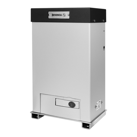
Beninca VN.MT40V User manual

VN.MT40V
UNIONE NAZIONALE COSTRUTTORI
AUTOMATISMI PER CANCELLI, PORTE
SERRANDE ED AFFINI
L8542365
11/2010 rev4


1
2
Soffitto.
Ceiling.
Decke.
Plafond.
Techo.
Sufit.
3

3
4
Parete.
Wall.
Wand.
Cloison.
Pared.
Ściana.
S
C
V
B
A
4

5
6
Z1
d
Z2
L1* L2* L3*
≥1x0,5mm
≥1x0,5mm
≥1x0,5mm
≥1x0,5mm
Elettrofreno
Electrobrake
Elektrobremse
Electro-frein
Electrofreno
Hamulec elektr.
,,*:
5
Finecorsa Apre
Open limit switch.
Fernschalter öffnet.
F.C. ouvre.
F.C. abre.
Krańcówka mech. otwierania
Messa a terra
Earth.
Erden.
Mise à la terre.
Conexión a tierra.
Uziemienie
Finecorsa chiude
Close limit switch.
Fernschalter schliesst.
F.C. ferme.
F.C. cierra.
Krańcówka mech. zamykania
Comune del contatto a disposizione
Common of the contact at disposal.
Gemeinsamer Leiter des entsprechenden Kontaktes.
Commun du contact disponible.
Común del contacto a disposición.
Wspólny styku do dyspozycji.
Non utilizzato
Not used.
Nicht verwendet.
Non utilisé.
No utilizado.
Nie używany
*
SWO
SWC
COM
AUX
COM
SW
AUX
* L1/L2/L3 ≥ 3x1,5mm

7
8
Collegamenti a stella per 400V trifase.
Star connection for 400V, three-phase.
Sternverbindung, dreiphasig für 400V.
Connexion étoile pour 400V triphasé.
Conexión estrella para 400V trifásica.
Połączenie gwiazdowe na 400V trójfazowy.
Collegamenti a triangolo per 230V trifase.
Triangle connection for 230V, three-phase.
Dreieckverbindung, dreiphasig für 230V.
Connexion triangle pour 230V triphasé.
Conexión triángulo para 230V trifásica.
Połączenie trójkątowe na 230V trójfazowy.
L1 L1L2 L2L3 L3
6
Blu.
Blue.
Blau.
Bleu.
Azul.
Niebieski.
Giallo.
Yellow.
Gelb.
Jaune.
Amarillo.
Żółty.
Nero.
Black.
Schwarz.
Noir.
Negro.
Czarny.
Arancio.
Orange.
Orange.
Orange.
Naranja.
Pomarańczowy.
Viola.
Violet.
Violett.
Violet.
Violeta.
Fioletowy.
Rosso.
Red.
Rot.
Rouge.
Rojo.
Czerwony.
Marrone + Bianco
Brown + White
Braun + weiß
Marron + Blanc
Marrón + Blanco
Brązowy + Biały
Bianco
White
weiß
Blanc
Blanco
Biały
Marrone
Brown
Braun
Marron
Marrón
Brązowy
*
SWO
SWC
COM
AUX
COM
SW
AUX

9
10
11
7

12
AUX
SWC
SWC AUX
COM SW
COM AUX.
BrownWhite
Orange
Yellow
Black
Violet
SAFETY SWITCH
Red
Blue
Yellow
Black
AUX
SWC
SWO
SWO SWC AUX
COM SW
COM AUX.
SWO XT
Red Brown
Brown
White
White Blue
SWO
SWO
SWO XT
Red Brown
White Blue
Orange
Yellow
Black
Violet
SAFETY SWITCH
BlackBlack
CIRCUIT BREAKER
Red
Blue
Yellow
Black
8

E' vietato l'utilizzo del prodotto per scopi o con modalità
non previste nel presente manuale. Usi non corretti posso-
no essere causa di danni al prodotto e mettere in pericolo
persone e cose.
Si declina ogni responsabilità dall'inosservanza della buona
tecnica nella costruzione dei cancelli, nonché dalle defor-
mazioni che potrebbero verificarsi durante l'uso.
Conservare questo manuale per futuri utilizzi.
L'installazione deve essere effettuata da personale quali-
ficato nel pieno rispetto delle normative vigenti.
I materiali dell'imballaggio non devono essere lasciati alla
portata dei bambini in quanto fonte di potenziale pericolo.
Non disperdere nell'ambiente i materiali di imballo, ma se-
parare le varie tipologie (es. cartone, polistirolo) e smaltirle
secondo le normative locali.
L’installatore deve fornire tutte le informazioni relative al
funzionamento automatico, manuale e di emergenza del-
l'automazione, e consegnare all’utilizzatore dell’impianto
le istruzioni d’uso.
AVVERTENZE
•Prevedere sulla rete di alimentazione un
interruttore/sezionatore onnipolare con distanza
d’apertura dei contatti uguale o superiore a 3 mm.
Verificare che a monte dell’impianto elettrico vi sia un interrut-
tore differenziale e una protezione di sovracorrente adeguati.
Alcune tipologie di installazione richiedono il collegamento
dell'anta ad un impianto di messa a terra rispondente alle
vigenti norme di sicurezza.
Durante gli interventi di installazione, manutenzione e ri-
parazione, togliere l’alimentazione prima di accedere alle
parti elettriche.
Le descrizioni e le illustrazioni presenti in questo manuale
non sono impegnative. Lasciando inalterate le caratteristi-
che essenziali del prodotto il fabbricante si riserva il diritto
di apportare qualsiasi modifica di carattere tecnico, co-
struttivo o commerciale senza impegnarsi ad aggiornare
la presente pubblicazione.
Dichiarazione CE di conformità
Fabbricante: Automatismi Benincà SpA.
Indirizzo: Via Capitello, 45 - 36066 Sandrigo (VI) - Italia
Dichiara che: l’automazione per cancelli battenti modelli
VN.MT40V
è conforme alle condizioni delle seguenti altre Direttive CE:
- DIRETTIVA 2004/108/CE DEL PARLAMENTO EUROPEO E DEL CONSIGLIO del 15
dicembre 2004 concernente il ravvicinamento delle legislazioni degli Stati membri relative
alla compatibilità elettromagnetica e che abroga la direttiva 89/336/CEE, secondo le seguenti
norme armonizzate: EN 61000-6-2:2005, EN 61000-6-3:2007.
- DIRETTIVA 2006/95/CE DEL PARLAMENTO EUROPEO E DEL CONSIGLIO del 12 dicembre
2006 concernente il ravvicinamento delle legislazioni degli Stati membri relative al materiale
elettrico destinato ad essere adoperato entro taluni limiti di tensione, secondo le seguenti
norme armonizzate: EN 60335-1:2002 + A1:2004 + A11:2004 + A12:2006 + A2:2006 +
A13:2008; EN 60335-1-103:2003.
Benincà Luigi, Responsabile legale.
Sandrigo, 10/06/2010.
9

ATTENZIONE
• Primadiprocedereall’installazioneleggereleistruzioniquiripor-
tate.
• ÈfattodivietoassolutodiutilizzareilprodottoVN.MT40Vper
applicazioni diverse da quelle contemplate dalle presenti istru-
zioni.
• Istruirel’utilizzatoreall’usodell’impianto.
• Consegnareall’utilizzatoreleistruzioniadessorivolte.
• TuttiiprodottiBenincàsonocopertidapolizzaassicurativache
risponde di eventuali danni a cose o persone causati da difetti di
fabbricazione, richiede però la marcatura CE della ”macchina” e
l’utilizzo di componenti originali Benincà.
LIMITI DI IMPIEGO ED AVVERTENZE
Questo motoriduttore è progettato per la motorizzazione di porte
sezionali industriali e serrande non bilanciate. Prima di procedere
all’installazione, verificare il bilanciamento (dove previsto) e lo
scorrimento della porta. Controllare lo stato delle funi, delle molle
e del sistema paracadute. Nel caso di porte non installate recen-
temente, controllare anche tutte le altre parti soggette ad usura.
Quanto sopra è determinante per la sicurezza dell’impianto e per
l’affidabilità dell’operatore.
INSTALLAZIONE
Grazie alla sua versatilità, il motoriduttore può essere montato non
solo a destra o a sinistra della porta, ma anche orizzontalmente (fig.
2) o verticalmente (fig. 3). Il motoriduttore è progettato per azionare
direttamente l’albero avvolgifuni della porta che deve avere un dia-
metro di 1" (25.4mm) ed essere provvisto di sede per chiavetta.
Per alberi avvolgifuni con diverso diametro è necessario un adatta-
tore (art. VN.A30 per alberi Ø 30, art. VN.A3175 per alberi Ø 31.75,
art. VN.A40 per alberi Ø 40). Per il fissaggio procedere come segue
(fig. 4):
• ControllarecheladistanzatraalberoavvolgifuniAelasupercie
a cui si deve staffare, sia compresa tra 82 e 150mm.
• SaldareoavvitarelastaffaSallasuperciestessa.
• Inlareil motoriduttore nell’alberoavvolgifuni interponendo la
chiavetta C.
• AvvitarelevitiVdiserraggio.
• PerilmontaggiodellapiastrasullatoButilizzarelevitiTEM10x20
in dotazione.
Per calcolare la velocità di movimento della porta procedere come
segue:
V = d (tamburo avvolgifuni - metri) x 3.14 x 24 = metri/1'
Èpossibile utilizzareil motoriduttore rinviandoil motoall’albero
avvolgifuni tramite una catena (art. VN.RM) trasmettendo eventual-
mente il moto in modo ridotto o moltiplicato (art. VN.RV) (fig. 5).
Per calcolare la velocità di movimento della porta procedere come
segue:
V = d (tamburo avvolgifuni - metri) x 3.14 x 24 x Z1 / Z2 = metri/1'
CABLAGGI (fig. 6)
Per utilizzare il microinterruttore a disposizione come finecorsa di
sicurezza in chiusura, modificare i cablaggi come da fig. 7.
N.B.: le versioni 400V trifase possono essere utilizzate anche in
230V trifase variando il collegamento da stella a triangolo come
da fig. 8.
REGOLAZIONE FINECORSA
Il motoriduttore è dotato di 4 microinterruttori:
Finecorsa rosso Finecorsa apertura (SWO)
Finecorsa blu Extra corsa apertura (SWO XT)
Finecorsa giallo Finecorsa chiusura (SWC)
Finecorsa nero A disposizione per accessori (AUX)
Per la regolazione delle camme procedere come segue:
• Azionaremanualmentela portano a portarlain posizionedi
quasi totale chiusura e regolare la camma SWC fino quasi ad
azionare il microinterruttore (fig. 9).
• Serrareilgranocomeingura10,utilizzandounachiaveabrugola
da 2,5mm.
• Conlamedesimachiaveeffettuarelaregolazionemicrometrica
della camma come in figura 11.
• Ripeterel’operazioneconlaportainaperturaeregolarelacamma
SWO.
• PosizionarepoilacammaSWOXTinmodocheintervengacon
un leggero ritardo rispetto alla camma SWO.
• Alimentarel’automazioneefarlafunzionare(selaprimamanovra
risulta di chiusura invertire i fili 1 e 3 dell’alimentazione motore
fig. 6).
• Nelcasosirendesseronecessarieulterioriregolazioniagiresul
grano di regolazione micrometrica.
In figura 12 è rappresentato lo schema di collegamento dei fine-
corsa.
Dati tecnici VN.MT40V
Alimentazione nomin.
Assorbimento nomin.
Potenza nominale
Coppia nominale
Foro albero uscita
Giri in uscita
*Rapp. riduzione F. C.
Intermittenza lavoro
Temp. funzionamento
Lubrificazione
Peso
Dimensioni: vedi fig.1
3x400V (50/60Hz)
2,2A
900W
185Nm
25,4mm
24rpm
1/40
80%
-20°C / +70°C
Agip Blasia 32
22,5kg
* Max. numero di giri eseguibile dall’albero di uscita.
Pesi teorici per serrande non bilanciate
(Kg)
Diametro tubo
(mm)
Forza sollevamento
(kg)
Peso max. serranda
(kg)
83 446 312
98 377 264
108 343 240
133 278 195
159 233 163
N.B.: Valori teorici influenzabili dalle condizioni di installazione.
10

The product shall not be used for purposes or in ways
other than those for which the product is intended for and
as described in this manual. Incorrect uses can damage
the product and cause injuries and damages.
The company shall not be deemed responsible for the
non-compliance with a good manufacture technique of
gates as well as for any deformation, which might occur
during use.
Keep this manual for further use.
Qualified personnel, in compliance with regulations in force,
shall install the system.
Packaging must be kept out of reach of children, as it can
be hazardous. For disposal, packaging must be divided
the various types of waste (e.g. carton board, polystyrene)
in compliance with regulations in force.
The installer must supply all information on the automatic,
manual and emergency operation of the automatic system
and supply the end user with instructions for use.
WARNING
•An omnipolar switch/section switch with remote
contact opening equal to, or higher than 3mm
must be provided on the power supply mains..
Make sure that before wiring an adequate differential
switch and an overcurrent protection is provided.
Pursuant to safety regulations in force, some types of in-
stallation require that the gate connection be earthed.
During installation, maintenance and repair, cut off power
supply before accessing to live parts.
Descriptions and figures in this manual are not binding.
While leaving the essential characteristics of the product
unchanged, the manufacturer reserves the right to modify
the same under the technical, design or commercial point
of view without necessarily update this manual.
EC Declaration of Conformity
Manufacturer: Automatismi Benincà SpA.
Address: Via Capitello, 45 - 36066 Sandrigo (VI) - Italia
Herewith declares that: the operator for hinged gates model
VN.MT40V
is complying with provisions set forth by the following other EC Directive:
- DIRECTIVE 2004/108/EC OF THE EUROPEAN PARLIAMENT AND OF THE COUNCIL
of 15 December 2004, on the harmonisation of the laws of Member States relating to
electromagnetic compatibility and which cancels Directive 89/336/EEC, according to the
following harmonised regulations: EN 61000-6-2:2005, EN 61000-6-3:2007.
- DIRECTIVE 2006/95/EC OF THE EUROPEAN PARLIAMENT AND OF THE COUNCIL of 12
December 2006, on the harmonisation of the laws of Member States relating to electrical
equipment designed for use with certain voltage limits, according to the following harmonised
regulations: EN 60335-1:2002 + A1:2004 + A11:2004 + A12:2006 + A2:2006 + A13:2008;
EN 60335-1-103:2003.
Benincà Luigi, Legal responsible.
Sandrigo, 10/06/2010.
11

WARNING
• Beforeinstallingtheautomaticsystemreadtheinstructions
hereunder carefully.
• ItisstrictlyforbiddentousetheproductVN.MT40V for applica-
tions other than indicated in this instruction handbook.
• Showtheuserhowtousetheautomationsystem.
• Givetheuserthepartoftheleaetwhichcontainstheinstructions
for users.
• AllBenincáproductsarecoveredbyaninsurancepolicyforany
possible damages to objects and persons caused by construc-
tion faults, under condition that the entire system be marked CE
and only Benincá parts be used.
OPERATING LIMITS AND WARNINGS
This gear motor has been studied to activate industrial sectional
doors and rolling gates without counterweights.
Before installation, check the correct balancing (where provided)
and the door sliding. Check that the ropes, the springs and the
parachuting system are in good conditions. For doors that have
not been installed recently, check also all the other parts subject
to wear and tear. The above instructions are essential for the safety
of the system and the reliability of the operator.
INSTALLATION
Thanks to its versatility, this geared motor can be assembled not
only on the right-side or left-side of the door, but also horizontally
(fig. 2) or vertically (fig. 3). The geared motor has been designed
to directly activate the cable winding shaft of the door which must
feature 1” diameter (25.4mm) and should be provided of housing
for the key. For cable winding shafts having a different diameter,
an adapter should be provided (item VN.A30 for diam. 30 shafts,
item VN.A3175 for diam. 31.75 shafts, item VN.A40 for diam. 40
shafts). To fit the unit proceed as follows (fig.4):
• Check that the distance between the rope coiler shaft “A” and
the surface onto which brackets should be fitted ranges between
82 and 150mm.
• Weld or fit the bracket “S” to surface with screws.
• Introduce the gear motor in the rope coiler shaft, while interposing
the key “C”.
• Tighten the fitting screws “V”.
• To mount the plate on side “B”, use screws TE M10x20 sup-
plied.
To calculate the movement speed of the door, proceed as fol-
lows:
V = d (diam. of cable winding drum - m) x 3.14 x 24 = m/1’
It is possible to use the geared motor by extending the motion to
the rope winding-up shaft by means of a chain (item VN.RM). The
motion can possibly be transmitted reduced or multiplied (item
VN.RV) (fig. 5).
To calculate the movement speed of the door, proceed as fol-
lows:
V = d (diam. of cable winding drum - m) x 3.14 x 24 x Z1 / Z2 = m/1’
WIRING (fig. 6)
To use the micro-switch supplied as a safety limit switch in the
closing phase, modify the cable positions as per fig. 7.
N.B.: Models 400V three-phase can be used also at 230V three-
phase by changing from a star connection to a triangle one as per
fig. 8.
ADJUSTMENT OF THE LIMIT SWITCHES
The geared motor is equipped with 4 microswitches:
Red limit switch Opening limit switch (SWO)
Blue limit switch Opening over-travel (SWO XT)
Yellow limit switch Closing limit switch (SWC)
Black limit switch At disposal of the accessories (AUX)
To adjust the cams proceed as follows:
• Manually move the door until it is almost closed and adjust the
SWC cam until the micro-switch is almost triggered (Fig. 9).
• TightenthedowelshowninFigure10byusinga2.5mmsocket
head key.
• Byusingthesamekey,carryoutthemicrometricadjustmentof
the cam, as shown in Figure 11.
• RepeattheoperationwhileopeningthedoorandadjusttheSWO
cam.
• ThenpositiontheSWOXTcamsothatitisactivatedslightly
delayed with respect to the SWO cam.
• Powertheautomaticunitandoperateit(ifitisaclosingoperation,
invert wires 1 and 3 of the motor power supply, fig. 6 and 7).
• Should further adjustments be required, turn the micrometric
adjustment dowel.
Figure 12 shows the wire diagram of limit switches.
Technical data VN.MT40V
Power supply
Consumption
Power
Torque
Exit shaft hole
Exit rounds
* L.S. reduction ratio
Jogging
Operat. temperature
Lubrication
Weight
Dimensions: see fig.1
3x400V (50/60Hz)
2,2A
900W
185Nm
25,4mm
24rpm
1/40
80%
-20°C / +70°C
Agip Blasia 32
22,5kg
* Max. no. of rounds from the exit shaft.
Theoretical weight for rolling gates
without counterweights (Kg)
Tube diameter
(mm)
Forza sollevamento
(kg)
Peso max. serranda
(kg)
83 446 312
98 377 264
108 343 240
133 278 195
159 233 163
N.B.: These theoretical values are affected by installation conditions
12

Das Produkt darf nicht für andere Zwecke oder auf andere
Weise verwendet werden, als in der vorliegenden Anlei-
tung beschrieben. Ein ungeeigneter Gebrauch kann das
Produkt beschädigen und eine Gefahr für Personen und
Sachen darstellen.
Wir übernehmen keinerlei Haftung für Schäden, die sich aus
einer unsachgerechten Montage der Tore und aus daraus
folgenden Verformungen ergeben können.
Bewahren Sie dieses Handbuch für Nachschlagzwecke
auf.
Die Installation darf nur von qualifizierten Fachleuten laut
den geltenden Vorschriften vorgenommen werden.
Das Verpackungsmaterial fern von Kindern halten, da es
eine potentielle Gefahr darstellt. Das Verpackungsmaterial
nicht ins Freie werfen, sondern je nach Sorte (z.B. Pappe,
Polystyrol) und laut den örtlich geltenden Vorschriften
entsorgen.
Der Installateur hat dem Benutzer alle Informationen über
den automatischen, manuellen Betrieb sowie den Not-
Betrieb der Automatik zusammen mit der Bedienungsan-
leitung zu liefern.
HINWEISE
•Das Stromnetz muss mit einem allpoligen
Schalter bzw. Trennschalter ausgestat-
tet sein, dessen Kontakte einen Öffnun-
gsabstand gleich oder größer als 3 aufweisen..
Kontrollieren, ob der elektrischen Anlage ein
geeigneter Differentialschalter und ein Über-
spannungsschutzschalter vorgeschaltet sind.
Einige Installationstypologien verlangen den Anschluss
des Flügels an eine Erdungsanlage laut den geltenden
Sicherheitsnormen.
Während der Installation, der Wartung und der Reparatur,
die Anlage stromlos machen bevor an den elektrischen
Teilen gearbeitet wird.
Die in diesem Handbuch enthaltenen Beschreibungen
und Abbildungen sind nicht verbindlich. Ausgenommen
der Haupteigenschaften des Produkts, behält sich der Her-
steller das Recht vor eventuelle technische, konstruktive
oder kommerzielle Änderungen vorzunehmen ohne dass
er vorliegende Veröffentlichung auf den letzten Stand
bringen muss.
EG-Konformitätserklärung
Hersteller: Automatismi Benincà SpA.
Adresse: Via Capitello, 45 - 36066 Sandrigo (VI) - Italia
Wirerklären,dass:AntriebefürDrehügeltore
VN.MT40V
sie entspricht folgenden EG-Richtlinien:
- RICHTLINIE 2006/95/EG DES EUROPÄISCHEN PARLAMENTS UND DES RATES vom
12. Dezember 2006 zur Angleichung der Rechtsvorschriften der Mitgliedstaaten über die
elektromagnetische Verträglichkeit und zur Aufhebung der Richtlinie 89/336/EWG, gemäß
nachstehenden harmonisierten Normen: EN 61000-6-2:2005, EN 61000-6-3:2007.
-
RICHTLINIE 2006/95/EG DES EUROPÄISCHEN PARLAMENTS UND DES RATES vom 12.
Dezember 2006 zur Angleichung der Rechtsvorschriften der Mitgliedstaaten betreffend elektrische
Betriebsmittel zur Verwendung innerhalb bestimmter Spannungsgrenzen, gemäß nachstehenden
harmonisierten Normen: EN 60335-1:2002 + A1:2004 + A11:2004 + A12:2006 + A2:2006 +
A13:2008; EN 60335-1-103:2003.
Benincà Luigi, Rechtsvertreter
Sandrigo, 10/06/2010.
13

ACHTUNG
• VorBeginnderMontagedieseAnleitungenlesen.
• Esiststengstensuntersagt,dasProduktVN.MT40V für andere
Zwecke zu verwenden, als die von den vorliegenden Anweisungen
beschriebenen Anwendungszwecke.
• DenBenutzerüberdenGebrauchderAnlageunterrichten.
• DemBenutzerdieTeilederBetriebsanleitungadgeben,diedie
auskunfte für den Benutzer enthaltet.
• AlleProdukteBenincàwurdenmiteinemVersicherungsschein
versehen, der alle eventuellen Schäden an Dingen oder Personen
abdeckt, die durch Herstellungsdefekte hervorgerufen wurden,
vorausgesetzt, das Gerät besitzt die Kennzeichnung EU und es
wurden original Benincà Einzelkomponenten verwendet.
ANWENDUNGSBESCHRÄNKUNGEN UND HINWEISE
Diesel Antrieb wurde für die Motorisierung von Sektionaltore und
nicht ausgeglichene Rolltore für den gewerblichen Bereich entwi-
ckelt. Vor der Installation den Ausgleich (wo vorgesehen) und das
Gleiten des Tores prüfen. Falls die Tür schon längere Zeit montiert
ist, auch die anderen Verschleissteile kontrollieren. Die oben auf-
geführten Anweisungen sind für die Sicherheit der Anlage und für
die Zuverlässigkeit des Bedieners massgebend.
INSTALLATION
Dank der Vielseitigkeit der Getriebemotoren können diese sowohl
rechts als auch links der Tür aber auch horizontal (Abb. 2) oder
vertikal montiert werden (Abb. 3). Der Getriebemotor ist entwickelt
worden, um direkt die Welle des Kabelwicklers der Tür zu steuern.
Die Welle muß einen Durchmesser von 1” (25.4mm) aufweisen und
mit einem Sitz für den Keil versehen sein. Für Kabelwicklerwellen mit
einem anderen Durchmesser muß ein Paßstück verwendet werden
(Art. VN.A30 für Wellen Ø 30, Art. VN.A3175 für Wellen Ø 31.75,
Art. VN.A40 für Wellen Ø 40). Zur Befestigung folgendermassen
vorgehen (abb.4):
• Den Abstand zwischen der Kabelwicklerwelle „A“ und der
Befestigungsäche kontrollieren; dieser muss 82 bis 150 mm
betragen.
• Den Bügel „S“ an dieselbe Fläche schweißen oder festschrau-
ben.
• Den Getriebemotor in die Kabelwicklerwelle stecken und dazwi-
schen den Keil „C“ einsetzen.
• Die Schrauben „V“ festziehen.
• Um die Platte auf der Seite „B“ zu montieren, die mitgelieferten
Schrauben TE M10x20 verwenden.
Um die Geschwindigkeit der Turbewegung auszurechnen, folgen-
dermassen vorgehen:
V = d (Durchmesser der Kabelwicklertrommel - m) x 3.14 x 24 = Meter/1’
Es kann auch ein Getriebemotor verwendet werden, um die Dre-
hung an die Kabelwicklerwelle durch eine Kette (Art. VN.RM) redu-
ziert oder multipliziert (Art. VN.RV) zu übertragen (Abb. 5).
Um die Geschwindigkeit der Turbewegung auszurechnen, folgen-
dermassen vorgehen:
V = d (Durchmesser der Kabelwicklertrommel - m) x 3.14 x 24 x Z1 / Z2 = Meter/1’
VERKABELUNGEN (abb. 6)
Um den Mikroschalter als Sicherheitsendschalter beim Schließen
zu verwenden, die Verkabelung laut Abb. 7 ändern.
N.B.: Die dreiphasigen Ausführungen für 400V können dreiphasig
auch für 230V verwendet werden, wenn der Stern-Dreieck-An-
schluss laut Abb. 8 geändert wird.
ENDSCHALTER EINSTELLEN
Der Getriebemotor ist mit 4 Mikroschaltern ausgestattet:
Roter Endschalter Endschalter für das Öffnen (SWO)
Blauer Endschalter
Für den extra Hub beim Öffnen (SWO XT)
Gelber Endschalter Endschalter zum Schliessen (SWC)
Schwarzer Endschalter
Zusatzlicher für Zubehör (AUX)
Zur Einstellung der Nocken folgendermassen vorgehen:
• Die Tür von Hand bewegen bis sie fast geschlossen ist. Den
SWC Nocken bis kurz vor dem Einschalten des Mikroschalters
einstellen (Abb. 9).
• DieStellschraubewieinAbbildung10gezeigt,mitHilfeeines
Inbusschlüssels zu 2,5 mm festziehen.
• MitdemselbenSchlüsseldieFeineinstellungdesNockenswie
in Abbildung 11 gezeigt, vornehmen.
• DenVorgangbeioffenerTurwiederholenunddenSWONocken
einstellen.
• DenSWOXTNockensopositionieren,daßerimverhältniszum
SWO Nocken etwas verspatet einschaltet.
• DieAutomatikmitStromspeisenundinBetriebsetzen(wenndie
Tur zuerst geschlossen wird, die Leiter 1 und 3 des Speisegeräts
des Motors umkehren, Abb. 6).
• Sollten weitere Einstellungen erforderlich sein, diese über die
Stellschraube für die Feineinstellung vornehmen.
Die Abbildung 12 zeigt das Anschlussschema der Endschalter.
Technische Daten VN.MT40V
Speisung
Stromaufnahme
Leistung
Drehmoment
Loch Wellenausgang
Upm am Ausgang
* Untersetzungsverhältnis
Betriebsschaltung
Betriebstemperatur
Schmierung
Gewicht
Masse: siehe Abb.1
3x400V (50/60Hz)
2,2A
900W
185Nm
25,4mm
24rpm
1/40
80%
-20°C / +70°C
Agip Blasia 32
22,5kg
* Max. Drehzahl der Ausgangswelle.
Theoretische Gewichte der nicht
ausgeglichenen Rolltore (Kg)
Rohrdurchmesser
(mm)
Zugkraft
(kg)
Max. Rolltorgewicht
(kg)
83 446 312
98 377 264
108 343 240
133 278 195
159 233 163
N.B.: Theoretische Werte, je nach Installation veränderlich
14

Il est interdit d’utiliser ce produit pour l’utilisation du pro-
duit ou avec des finalités ou modalités non prévues par le
présent manuel. Toute autre utilisation pourrait compro-
mettre l’intégrité du produit et présenter un danger pour
les personnes ou pour les biens.
Le fabricant décline toute responsabilité en cas d’utilisation
impropre ou d’inobservation de la bonne technique dans la
construction des portails, ainsi que de toute déformation
qui pourrait avoir lieu lors de son utilisation.
Toujours conserver la notice pour toute autre consultation
future.
L’installation doit être faite uniquement par un personnel
qualifié dans le respect total des normes en vigueur.
Tenir à l’écart des enfants tous les matériaux d’emballage
car ils représentent une source potentielle de danger. Ne
pas disperser les matériaux d’emballage dans l’environne-
ment, mais trier selon les différentes typologies (i.e. carton,
polystyrène) et les traiter selon les normes locales.
L’installateur doit fournir toutes les informations relatives
au fonctionnement automatique, au déverrouillage d’ur-
gence de l’automatisme, et livrer à l’utilisateur les modes
d’emploi.
REGLES DE SECURITE’
•Prévoir sur le réseau de l’alimentation un interrup-
teur / sectionneur omnipolaire avec distance d’ou-
verture des contacts égale ou supérieure à 3 mm..
Vérifier la présence en amont de l’installation électrique
d’un interrupteur différentiel et d’une protection de sur-
courant adéquats.
Certains types d’installation requièrent le branchement du
vantail à une installation de mise à terre satisfaisant les
normes de sécurité e vigueur.
Avant toute intervention, d’installation, réparation et main-
tien, couper l’alimentation avant d’accéder aux parties
électriques.
Les descriptions et les illustrations présentées dans ce
manuel ne sont pas contraignantes. En laissant inaltérées
les caractéristiques essentielles du produit, le fabricant se
réserve le droit d’apporter toute modification à caractère
technique, de construction ou commerciale sans s’engager
à revoir la cette publication.
Déclaration CE de conformité
Fabricant: Automatismi Benincà SpA.
Adresse: Via Capitello, 45 - 36066 Sandrigo (VI) - Italia
Déclaire ci-apres que: l’automation pour portails ouvrants
VN.MT40V
elle satisfait les conditions des autres Directives CE ci-dessous:
- DIRECTIVE 2004/108/CE DU PARLEMENT EUROPÉEN ET DU CONSEIL du 15 dècembre
2004 concernant le rapprochement des legislations des États membres relatives à la
compatibilité électromagnétique et abrogeant la directive 89/336/CEE, selon les suivantes
normes harmonisées: EN 61000-6-2:2005, EN 61000-6-3:2007.
- DIRECTIVE 2006/95/CE DU PARLEMENT EUROPÉEN ET DU CONSEIL du 12 décembre
2006 concernant le rapprochement des legislations des États membres relatives au materiel
électrique destiné à être employé dans certaines limites de tension ,selon les suivantes
normes harmonisées: EN 60335-1:2002 + A1:2004 + A11:2004 + A12:2006 + A2:2006 +
A13:2008; EN 60335-1-103:2003.
Benincà Luigi, Responsable légal.
Sandrigo, 10/06/2010.
15

ATTENTION
• Avantdeprocéderàl’installation,lirelesinstructionscontenues
dans ce manuel.
• Ilestimpérativementinterditd’utiliserleproduitVN.MT40V pour
des applications différentes de celles énoncées dans les présen-
tes instructions.
• Fourniràl’utilisateurlesrenseignementssurl’emploidel’instal-
lation.
• Donneràl’utilisateurlapartiedulivretd’instructionsquicontient
les renseignements pour l’utilisation.
• TouslesproduitsBenincàsontcouvertsparunepoliced’assu-
rance qui répond d’éventuels préjudices corporels ou matériels
provoqués à cause de défauts de fabrication, mais qui requiert
toutefois le marquage CE de la “machine” et l’utilisation de pièces
de rechange d’origine Benincà.
LIMITES D’EMPLOI ET AVERTISSEMENTS
Ce motoréducteur est conçu pour la motorisation de portes sec-
tionnelles industrielles et de rideaux non équilibrés. Avant de pro-
céder à l’installation, vérifier l’équilibrage (si prévu) et le coulisse-
ment de la porte. Contrôler le bon état des câbles, des ressorts
et du système parachute. Si les portes n’ont pas été installées
récemment, contrôler aussi toutes les autres parties sujettes à
l’usure. Les instructions qui précèdent sont déterminantes pour la
sécurité de l’installation et pour la fiabilité de l’opérateur.
INSTALLATION
Grâce à sa versatilité, le présent motoréducteur peut être monté
non seulement à droite ou à gauche de la porte, mais aussi hori-
zontalement (fig. 2) ou verticalement (Fig. 3). Le motoréducteur est
conçu pour actionner directement l’arbre d’enroulement du câble
de la porte, dont le diamètre doit être de 1” (25.4mm) et il doit être
doté d’un siège pour la clavette. Pour les arbres d’enroulement des
câbles ayant un diamètre différent il faudra prévoir un adaptateur
(art. VN.A30 pour arbres Ø 30, art. VN.A3175 pour arbres Ø 31.75,
art. VN.A40 pour arbres Ø 40). Pour la fixation, suivre la marche
ci-dessous (fig. 4):
• contrôler que la distance entre l’arbre d’enroulement des câbles
„A“ et la surface à laquelle il doit être bridé est comprise entre
82 et 150mm.
• Souder ou visser la bride ”S” sur la surface même.
• Introduire le motoréducteur dans l’arbre d’enroulement des
câbles en intercalant la clavette ”C”.
• Visser les vis ”V” de serrage.
• Pour l’assemblage de la plaque sur le côté ”B” utiliser les vis TE
M10x20 fournies.
Pour calculer la vitesse de déplacement de la porte, suivre la mar-
che ci-dessous :
V = d (tambour d’enroulement des câbles - m) x 3,14 x 24 = mètres/1’
Possibilité d’utiliser le motoréducteur en renvoyant le mouvement
à l’arbre d’enroulement des câbles par le biais d’une chaîne (article
VN.RM), avec transmission éventuelle du mouvement de manière
réduite ou multipliée (article VN.RV) (Fig. 5).
Pour calculer la vitesse de mouvement de la porte, suivre la marche
ci-dessous :
V = d (tambour d’enroulement des câbles - m) x 3,14 x 24 x Z1 / Z2 = mètres/1’
CÂBLAGES (fig. 6)
Pour utiliser le microcontact disponible comme fin de course de
sécurité en fermeture, modifier les câblages conformément à la
fig. 7.
N.B.: Les versions 400V triphasé peuvent également être utilisées
en 230V triphasé en changeant la connexion d’étoile à triangle,
suivant la marche illustrée à la fig.8.
REGLAGE FINS DE COURSE
Le motoréducteur est doté de 4 microcontacts:
Fin de course rouge Fin de course d’ouverture (SWO)
Fin de course bleue Extra-course d’ouverture (SWO XT)
Fin de course jaune Fin de course de fermeture (SWC)
Fin de course noire Libre pour les accessoires (AUX)
Pour le réglage des cames suivre la marche ci-dessous:
• Actionner manuellement la porte jusqu’à atteindre la position de
fermeture presque totale et régler la came SWC jusqu’à presque
actionner le micro interrupteur (fig. 9).
• Serrerlegraincommeillustrédanslagure10,àl’aided’uneclé
Allen 2,5mm.
• Aveclamêmecléexécuterleréglagemicrométriquedelacame
comme indiqué dans la figure 11.
• répéterl’opérationaveclaporteenouvertureetréglerlacame
SWO;
• ensuite,mettreenplacelacameSWOXTdemanièreàcequ’elle
intervienne avec un léger retard par rapport à la came SWO;
• alimenterl’automatismeetlafairefonctionner(silapremière
manœuvre s’avère de fermeture, inverser les fils 1 et 3 de
l’alimentation du moteur Fig. 6).
• Au besoin, pour d’ultérieurs réglages agir sur le grain de réglage
micrométrique.
La figure 12 illustre le schéma des branchements des fins de cour-
se.
Donnees technique VN.MT40V
Alimentation
Absorption
Puissance
Couple
Trou arbre sortie
Nb. de tours en sortie
* Demultiplication F.C.
Intermittence travail
Temp. fonctionnement
Lubrification
Poids
Dimensions: voir fig.1
3x400V (50/60Hz)
2,2A
900W
185Nm
25,4mm
24rpm
1/40
80%
-20°C / +70°C
Agip Blasia 32
22,5kg
* Nombre de tours maximum de l’arbre de sortie.
Poids théoriques pour rideaux
non équilibrés (Kg)
Diamètre tube
(mm)
Force de levage
(kg)
Poids max. rideau
(kg)
83 446 312
98 377 264
108 343 240
133 278 195
159 233 163
N.B.: Valeurs théoriques pouvant être influencées par les conditions d’installation.
16

Está prohibido utilizar el producto para finalidades o con
modalidades no previstas en el presente manual. Usos
incorrectos pueden causar daños al producto y poner en
peligro personas y cosas.
Se rehúsa cualquier responsabilidad en caso de incum-
plimiento de la buena técnica en la construcción de las
cancelas, así como en cuanto a las deformaciones que
pudieran producirse durante el uso.
Guardar este manual para futuras consultas.
La instalación debe ser efectuada por personal cualificado
respetando plenamente las normas vigentes.
Los elementos del embalaje no se deben dejar al alcance
de los niños ya que son potenciales fuentes de peligro.
No tirar al medio ambiente los elementos del embalaje,
sino que se deben separar según los varios tipos (por ej.
cartón, poliestireno) y evacuarlos de conformidad con las
normas locales.
El instalador debe proporcionar todas las informaciones
relativas al funcionamiento automático, manual y de
emergencia de la automatización y entregar al usuario
del equipo las instrucciones de uso.
ADVERTENCIAS
•Prever en la red de alimentación un interruptor/
cortacircuitos omnipolar con distancia de aper-
tura de los contactos igual o mayor que 3 mm.
Comprobar que entre el aparato y la red eléctrica
general haya un interruptor diferencial y una pro-
tección contra sobrecorriente adecuados.
Algunos tipos de instalación requieren que se conecte la
hoja con una instalación de puesta a tierra conforme a las
vigentes normas de seguridad.
Durante las operaciones de instalación, mantenimiento y
reparación, cortar la alimentación antes de acceder a las
partes eléctricas.
Las descripciones y las ilustraciones presentadas en este
manual no son vinculantes. Sin cambiar las características
esenciales del producto, el fabricante se reserva el dere-
cho de aportar cualquier modificación de carácter técnico,
constructivo o comercial sin obligación de actualizar la
presente publicación.
Declaración CE de conformidad
Fabricante: Automatismi Benincà SpA.
Dirección: Via Capitello, 45 - 36066 Sandrigo (VI) - Italia
Declara que: la automatización para cancelas de batiente
VN.MT40V
cumple las condiciones de las siguientes otras Directivas CE:
- DIRECTIVA 2004/108/CE DEL PARLAMENTO EUROPEO Y DEL CONSEJO del 15 de
diciembre de 2004 sobre la aproximación de las legislaciones de los Estados miembros con
relación a la compatibilidad electromagnética y que abroga la Directiva 89/336(CEE, según
las siguientes normas armonizadas: EN 61000-6-2:2005, EN 61000-6-3:2007.
- DIRECTIVA 2006/95/CE DEL PARLAMENTO EUROPEO Y DEL CONSEJO del 12 de diciembre
de 2006 sobre la aproximación de las legislaciones de los Estados miembros con relación al
material eléctrico destinado a ser utilizado dentro de determinados límites de tensión, según
las siguientes normas armonizadas: EN 60335-1:2002 + A1:2004 + A11:2004 + A12:2006 +
A2:2006 + A13:2008; EN 60335-1-103:2003.
Benincà Luigi, Responsable legal.
Sandrigo, 10/06/2010.
17

ATENCIÓN
•Antes de proceder a la instalación leer las instrucciones aquí
aportadas.
• EstáabsolutamenteprohibidoutilizarelproductoVN.MT40V para
aplicaciones diversas a aquellas contempladas en las presentes
instrucciones.
• Instruiralusuariosobreelusodelainstalación.
• Entregaralusuariolasinstruccionesquelecorresponden.
• TodoslosproductosBenincàestáncubiertosporlapólizade
seguros que responde de eventuales daños a personas o cosas
causados por defectos de fabricación, pero require para ello la
marca CE de la ”maquinaria” y la utilización de componentes
originales Benincà.
LÍMITES DE UTILIZACIÓN Y ADVERTENCIAS
Este motorreductor ha sido proyectado para la motorización de
puertas seccionales industriales y cierres no balanceados. Antes
de proceder con la instalación, comprobar el equilibrio (cuando
previsto) y el deslizamiento de la puerta. Comprobar el estado de
los cables, de los muelles y del sistema paracaídas. En el caso
de puertas no instaladas recientemente, comprobar también to-
das las demás partes sujetas a desgaste. Lo antedicho es funda-
mental para la seguridad de la instalación y para la fiabilidad del
operador.
INSTALACIÓN
Gracias a su versatilidad, el motorreductor se puede montar no sólo
a la derecha o la izquierda de la puerta, sino también horizontal (fig.
2) o verticalmente (fig. 3). El motorreductor está diseñado para ac-
cionar directamente el eje enrollacables de la puerta, que debe tener
un diámetro de 1” (25.4mm) y disponer de sede para chaveta.
Para ejes enrollacables de diámetro diferente es preciso emplear
un adaptador (art. VN.A30 para ejes Ø 30, art. VN.A3175 para ejes
Ø 31.75, art. VN.A40 para ejes Ø 40). Para la fijación proceder
como sigue (fig. 4):
• Comprobar que la distancia entre eje de enrollamiento de cables
”A” y la superficie a la cual se debe fijar sea entre 82 y 150mm.
• Soldaroenroscarelestribo“S”adichasupercie.
• Insertarelmotorreductorenelejedeenrollamientodecables
intercalando la chaveta ”C”.
• Enroscarlostornillos“v”deapriete.
• Paraelmontajedelaplacaenellado”B”utilizarlostornillosCH
M10x20 suministrados.
Para calcular la velocidad de movimiento de la puerta proceder
como sigue:
V = d (tambor enrollacables - m) x 3.14 x 24 = metros/1’
Es posible utilizar el motorreductor transmitiendo el movimiento
al eje enrollador mediante una cadena (art. VN.RM), transmitiendo
eventualmente el movimiento de manera reducida o multiplicada
(art. VN.RV) (fig. 5).
Para calcular la velocidad de movimiento de la puerta proceder
como sigue:
V = d (tambor enrollacables - m) x 3.14 x 24 x Z1 / Z2 = metros/1’
CABLEADOS (fig. 6)
Para utilizar el microinterruptor a disposición como final de carrera
de seguridad en cierre, modificar los cableados como mostrado
en la fig. 7.
N.B.:Las versiones 400V trifásica pueden ser utilizadas también
con 230V trifásica cambiando la conexión de estrella a triángulo,
procediendo como mostrado en la fig. 8.
AJUSTE FINAL DE CARRERA
El motorreductor dispone de 4 microinterruptores:
Final de carrera roja Final de carrera apertura (SWO)
Final de carrera azul Extracarrera apertura (SWO XT)
Final de carrera amarilla Final de carrera cierre (SWC)
Final de carrera negra A disposición para accesorios (AUX)
Para el ajuste de las excéntricas proceder como sigue:
• Accionar manualmente la porta hasta llevarla a la posición de
cierre casi total y ajustar la excéntrica SWC hasta casi accionar
el microinterruptor (fig. 9).
• Apretarelprisionerocomoenlagura10,utilizandounallave
Allen de 2,5mm.
• Conlamismallaveefectuarelajustemicrométricodelaexcén-
trica como en la figura 11.
• Repetirlaoperaciónconlapuertaenaperturayajustarlaexcén-
trica SWO.
• Colocarseguidamente laexcéntrica SWO XT de maneraque
se dispare con un ligero retraso con respecto a la excéntrica
SWO.
• Alimentarla automatización yhacerla funcionar (sila primera
maniobra es de cierre cabe invertir los hilos 1 y 3 de la aliment-
ación del motor fig. 6).
• Si fuesen necesarios ulteriores ajustes, actuar sobre el prisionero
de ajuste micrométrico.
En la figura 12 se muestra el esquema de conexión de los finales
de carrera.
Datos técnicos VN.MT40V
Alimentación
Consumo
Potencia
Par
Agujero eje salida
Revoluciones en salida
* Relación reducción
Intermitencia operación
Temp. funcionamiento
Lubrificación
Peso
Medidas: ver fig.1
3x400V (50/60Hz)
2,2A
900W
185Nm
25,4mm
24rpm
1/40
80%
-20°C / +70°C
Agip Blasia 32
22,5kg
* Max. r.p.m. en el eje de salida.
Pesos teóricos para cierres
no balanceados (Kg)
Diámetro tubo
(mm)
Fuerza elevación
(kg)
Peso máx. cierre
(kg)
83 446 312
98 377 264
108 343 240
133 278 195
159 233 163
N.B.: Valores teóricos que los que pueden repercutir las condiciones de instalación.
18

Zabrania się używania produktu do celów i w sposób inny
niż przewidziane w niniejszym podręczniku. Nieprawidłowe
używanie może spowodować uszkodzenie produktu i
stanowić zagrożenie dla osób i rzeczy.
Nie bierze się na siebie żadnej odpowiedzialności za
nieprzestrzeganie reguł dobrej techniki budowlanej przy
realizacji bram, a także w przypadku odkształceń, które
mogłyby powstać w trakcie użytkowania.
Przechowywać niniejszy podręcznik do przyszłego
użytku.
Instalacja musi być wykonana przez wykwalifikowany
personel z zachowaniem wszelkich obowiązujących pr-
zepisów prawnych.
Nie można pozostawiać opakowania w miejscach
dostępnych dla dieci, ponieważ może to być niebezpieczne.
Nie pozostawiać opakowania w środowisku, tylko podzielić
na poszczególne kategorie odpadów (n.p. karton, polistyrol)
i zlikwidować je zgodnie z obowiązującymi przepisami
miejscowymi.
Instalator zobowiązany jest do udzielenia wszelkich
informacji dotyczących działania w trybie automatycznym,
ręcznym i w przypadku zaistnienia stanu alarmowego
automatyzacji i wręczyć użytkownikowi instalacji instrukcję
użytkowania.
OSTRZEŻENIA
•Należy przewidzieć w sieci wyłącznik/odłącznik sek-
cyjny wielobiegunowy, gdzie odległość rozwarcia
między stykami będzie równa lub większa 3 mm..
Sprawdzić, czy przed instalacją elektryczną jest odpowie-
dni wyłącznik dyferencjalny i zabezpieczenie przed
przetężeniem.
Niektóre typologie instalacji wymagają podłączenia
skrzydła do uziemienia zgodnego z obowiązującymi nor-
mami bezpieczeństwa.
Podczas prac instalacyjnych, konserwacji i naprawy, przed
przystąpieniem do prac na częściach elektrycznych należy
odciąć zasilanie.
Opisy i ilustracje znajdujące się w niniejszym podręczniku
podane są wyłącznie przykładowo. Pozostawiając niez-
mienione istotne charakterystyki techniczne produktu,
producent zastrzega sobie prawo do wprowadzania każdej
zmiany o charakterze technicznym, konstrukcyjnym lub
handlowym, bez konieczności modyfikowania niniejszej
publikacji.
Deklaracja zgodności z normą CE
Producent: Automatismi Benincà SpA.
Adres: Via Capitello, 45 - 36066 Sandrigo (VI) - Italia
Oświadcza że: Automatyzm do bram uchylnych model
VN.MT40V
zgodne jest z wymogami innych, niżej podanych Dyrektyw CE:
- DYREKTYWY 2004/108/WE RADY PARLAMENTU EUROPEJSKIEGO z dnia 15 grudnia 2004
w sprawie zbliżania ustawodawstwa państw członkowskich w zakresie kompatybilności
elektromagnetycznej i anulującej postanowienia Dyrektywy 89/336/EWG, zgodnie z
następującymi normami zharmonizowanymi: EN 61000-6-2:2005, EN 61000-6-3:2007.
- DYREKTYWY 2006/95/WE RADY PARLAMENTU EUROPEJSKIEGO z dnia 12 grudnia
2006 w sprawie zbliżania ustawodawstwa państw członkowskich w zakresie sprzętu
elektrycznego przeznaczonego do użytku w ramach wyznaczonych wartości napięcia,
zgodnie z następującymi normami zharmonizowanymi: EN 60335-1:2002 + A1:2004 +
A11:2004 + A12:2006 + A2:2006 + A13:2008; EN 60335-1-103:2003.
Benincà Luigi, Odpowiedzialny za kwestie prawne.
Sandrigo, 10/06/2010.
19

UWAGA
• Przedprzystąpieniemdomontażuurządzenianależyzapoznać
się z niżej podanymi instrukcjami.
• Jestabsolutnie zabronione używanie produktu VN.MT40V do
zastosowania innego niż podane w niniejszej instrukcji.
• Należypouczyćużytkownikaosposobieużytkowaniaurządze-
nia.
• Należy przekazać użytkownikowi instrukcje obsługi przeznaczone
dla niego.
• WszystkieproduktyBenincàposiadająpolisęubezpieczeniową
o odpowiedzialności cywilnej, która zapewnia odszkodowanie
za szkody poniesione przez rzeczy lub osoby spowodowane
wadami produkcyjnymi pod warunkiem, że urządzenie będzie
sygnowane znakiem CE i że wszystkie jego komponenty będą
oryginalnymi częściami Benincà.
OGRANICZENIA ZASTOSOWANIA URZĄDZENIA I
STRZEŻENIA
Motoreduktor ten został zarojektowany w celu automatyzacji
przemysłowych bram sekcyjnych i żaluzji (krat) bez przeciwwagi.
Przed przystąpieniem do montażu urządzenia należy sprawdzić
przeciwwagę (tam, gdzie jest ona przewidziana) i przesuw bramy.
Ponadto należy sprawdzić stan techniczny linek, sprężyn i syste-
mu olinowania hamowania. W przypadku bram zamontowanych
od dawna należy również sprawdzić wszystkie elementy podatne
na zużycie. Jest to konieczne dla zapewnienia bezpieczeństwa i
prawidłowego działania urządzenia.
MONTAŻ
Dzięki swojej konstrukcji uniwersalnej motoreduktor może być za-
montowany nie tylko po prawej lub lewej stronie bramy, ale także w
pionie (rys. 2) lub w poziomie. (rys. 3). Motoreduktor pomyślany jest
tak, żeby bezpośrednio działać na wałek napędu bramy; którego
średnica musi wynosić 1” (25.4mm) i który musi być wyposażony
w klin wpustowy. Gdyby okazało się, że wałek ma średnicę inną
niż podana powyżej, należy zamontować złączkę (art. VN.A30 dla
wałków Ø 30, art.VN.A3175 dla wałków Ø 31.75, art. VN.A40 dla
wałków Ø 40). W celu przymocowania należy postępować jak po-
dano poniżej (rys. 4):
• Sprawdzić, czy odległość między wałem nawijania liny ”A”, a
powierzchnią mocującą jest zawarta między 82 a 150mm.
• Przyspawać lub przykręcić wspornik ”S” do powierzchni
mocującej.
• Włożyć motoreduktor do wału nawijania lin wsuwając wpust
”C”.
• Przykręcićśruby”V”mocujące.
• Do montażu płyty po stronie ”B” użyć dostarczonych śrub TE
M10x20.
W celu obliczenia szybkości przesuwu bramy należy postępować
według wzoru podanego poniżej.
Sz. = średn. (bębna nawijania liny - metry) x 3.14 x 24 = metrów/1’
Można używać motoreduktora jako napędu wału napędu bramy
poprzez zastosowanie łańcucha Galla (art. VN.RM), z ewentualnym
zastosowaniem przekładni redukcyjnej w celu zredukowania lub
zwiększenia obrotów (art. VN.RV) (rys. 5).
W celu obliczenia szybkości przesuwu bramy należy postępować
według wzoru podanego poniżej.
Sz. = średn. (bębna nawijania liny - metry) x 3.14 x 24 x Z1 / Z2 = metrów/1’
OKABLOWANIE (rys. 6)
W celu zastosowania mikrowyłącznika do dyspozycji jako krańcówki
mechanicznej bezpieczeństwa przy zamykaniu należy zmienić
okablowanie tak jak to pokazano na rys. 7.
UWAGA: Wersja 400V trójfazowa może być używana także przy
zasilaniu 230V trójfazowym po zmianie połączeń z gwiazdowego
na trójkątowe, tak jak to jest pokazane na rys. 8.
KALIBROWANIE KRAŃCÓWKI MECHANICZNEJ
Motoreduktor wyposażony jest w cztery mikrowyłączniki, wśród
których:
Krańcówka czerwona
Mikrowyłącznik krańcówki mechanicznej otwierania (SWO)
Krańcówka niebieskal
Suwu otwierania (SWO XT)
Krańcówka żółta
Krańcówki mechanicznej zamykania (SWC)
Krańcówka czarna
Wolny dla ewentualnych akcesoriów (AUX)
W celu kalibrowania krzywek należy postępować tak jak to podano
poniżej:
• Ręcznie uruchomić drzwi i ustawić je w położeniu prawie
całkowitego zamknięcia oraz wyregulować SWC krzywkę prawie
do włączenia mikrowyłącznika (rys. 9).
• Dokręcićkołekgwintowany,jakprzedstawiononarysunku10,
posługując się w tym celu kluczem imbusowym 2,5mm.
• Zapomocątegosamegokluczawyregulowaćmikrometrycznie
krzywkę, jak przedstawiono na rysunku 11.
• Powtórzyć tę samą operację przy bramie w pozycji otwarcia i
wyregulować krzywkę SWO.
• Następnienależy wyregulować krzywkę SWO XT w taki sposób,
żeby działała ona z lekkim opóźnieniem w stosunku do działania
krzywki SWO.
• Podłączyćzasilanie iwłączyć urządzenieautomatyzacji (jeżeli
pierwsza operacja okaże się cyklem zamykania, należy zamienić
złącza 1 i 3 silnika – zobacz rys. 6).
• W razie konieczności przeprowadzenia dalszej regulacji należy
posłużyć się kołkiem do regulacji mikrometrycznej.
Na rysunku 12 przedstawiono schemat podłączenia wyłączników
krańcowych.
Dane techniczne VN.MT40V
Napięcie zasilania
Pobór prądu
Pobór mocy
Moment obrotowy
Otwór wału zdawczego
Obroty na wyjściu
* Przełożenie przekładni
Przerywacz pracy
Temperatura działania
Smarowanie
Ciężar
Wymiary: zobacz rys.1
3x400V (50/60Hz)
2,2A
900W
185Nm
25,4mm
24rpm
1/40
80%
-20°C / +70°C
Agip Blasia 32
22,5kg
* Maks. liczba obrotów wału zdawczego.
Teoretyczny ciężar żaluzji (krat)
bez przeciwwagi (Kg)
Średnica rury
(mm)
Siła podnoszenia
(kg)
Max. ciężar żaluzji (kraty)
(kg)
83 446 312
98 377 264
108 343 240
133 278 195
159 233 163
N.B.: Parametry teoretyczne mogą ulec zmianie w zależności od warunków w jakich
żaluzja (krata) będzie montowana.
20
Other manuals for VN.MT40V
1
Table of contents
Languages:
Other Beninca Controllers manuals
Popular Controllers manuals by other brands

Norac
Norac UC4+ New Navigator 2007+ installation manual

LeakSmart
LeakSmart Snap Valve Controller System user manual

Festo
Festo DFPD-Series Translation of the original instructions

Honeywell
Honeywell MS 10 Series manual

Fulling Motor
Fulling Motor MD2278 user manual

Luster Teraband Photonics
Luster Teraband Photonics CableTRAN MoCA1.1 user manual