Hypercable TwinRadio HYC-Wi 2000 User manual

User Manual
Includes install, configuration and trouble
shooting information for the broadband
wireless access outdoor radio.
TwinRadio HYC-Wi 2000
Gigabit Full Duplex Radio Link 24 GHz
XPIC FDD Radio PTP Bridge IP Link
www.hypercable.fr www.e-rake.fr

Full Outdoor 2+0 XPIC IP Link
Page 2 of 39 Version 1.0
1 SPU Description. ........................................................................................................................................ 4
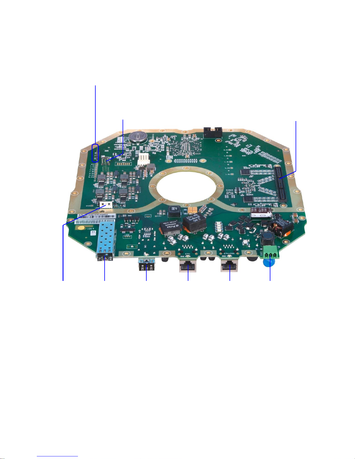
1.1 Service connectors............................................................................................................................. 4
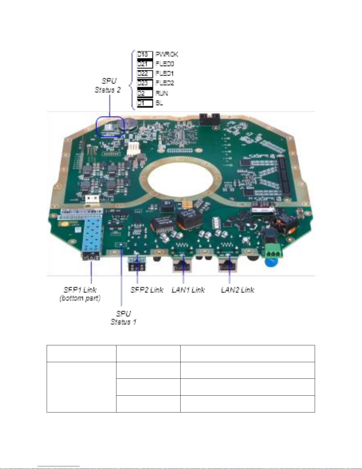
1.2 Status LEDs ........................................................................................................................................ 7
1.3 Interface LED ..................................................................................................................................... 7
1.4 Power supply ................................................................................................................................... 10
2 Management Introduction ...................................................................................................................... 10
2.1 Management access ........................................................................................................................ 10
2.2 Local and remote setting................................................................................................................. 11
2.3 Storing the configuration and the configuration scope .................................................................. 11
3 First configuration steps.......................................................................................................................... 12
3.1 Connection and Login...................................................................................................................... 12
3.2 General system configurations........................................................................................................ 13
3.3 IP configurations.............................................................................................................................. 14
3.4 Modem and Radio configurations................................................................................................... 14
4 Graphical User Interface (WEB GUI)........................................................................................................ 15
4.1 Web header & Side panel description............................................................................................. 15
4.2 General ............................................................................................................................................ 16
4.2.1 Status ....................................................................................................................................... 16
4.2.2 Mode ....................................................................................................................................... 16
4.3 Info................................................................................................................................................... 17
4.3.1 License ..................................................................................................................................... 17
4.3.2 Date ......................................................................................................................................... 17
4.3.3 Users ........................................................................................................................................ 17
4.4 Alarms Page ..................................................................................................................................... 17
4.4.1 Status ....................................................................................................................................... 17
4.4.2 Alarm Conf............................................................................................................................... 18
4.4.3 Logs.......................................................................................................................................... 19
4.5 Radio Page ....................................................................................................................................... 19
4.5.1 Parameters .............................................................................................................................. 19
4.5.2 Analyser ................................................................................................................................... 20
4.5.3 Diagram ................................................................................................................................... 21
4.5.4 ACM ......................................................................................................................................... 21
4.5.5 Advanced ................................................................................................................................. 22
4.5.6 Details...................................................................................................................................... 22
www.hypercable.fr www.e-rake.fr

Full Outdoor 2+0 XPIC IP Link
Page 3 of 39 Version 1.0
4.6 Ports Page........................................................................................................................................ 23
4.6.1 Parameters .............................................................................................................................. 23
4.6.2 ETH VLAN................................................................................................................................. 24
4.6.3 ETH Advanced.......................................................................................................................... 26
4.7 IP Page ............................................................................................................................................. 27
4.7.1 Address .................................................................................................................................... 27
4.7.2 Route/NAT ............................................................................................................................... 28
4.7.3 SNMP ....................................................................................................................................... 29
4.7.4 Advanced ................................................................................................................................. 29
4.8 Count Page....................................................................................................................................... 30
4.8.1 Basic/BER ................................................................................................................................. 30
4.8.2 Ethernet................................................................................................................................... 31
4.8.3 Management ........................................................................................................................... 31
4.8.4 Graphs...................................................................................................................................... 31
4.8.5 Online Graphs .......................................................................................................................... 32
4.9 Maintenance Page........................................................................................................................... 32
4.9.1 Config....................................................................................................................................... 32
4.9.2 Terminal................................................................................................................................... 32
4.9.3 Files.......................................................................................................................................... 32
4.9.4 Advanced ................................................................................................................................. 33
5 Command Line Interface (CLI) ................................................................................................................. 35
5.1 Basic command structure................................................................................................................ 35
5.2 Altering device configuration using CLI –enable mode .................................................................. 36
5.3 CLI command abbreviations ............................................................................................................ 36
5.4 CLI online help ................................................................................................................................. 36
6 Simple Network Mangament Protocol (SNMP)....................................................................................... 37
6.1 Basic SNMP setting .......................................................................................................................... 37
6.2 MIB .................................................................................................................................................. 38
6.3 Traps ................................................................................................................................................ 38
6.4 Altering device configuration using SNMP ...................................................................................... 38
www.hypercable.fr www.e-rake.fr

Full Outdoor 2+0 XPIC IP Link
Page 4 of 39 Version 1.0
1SPU Description.
1.1 Service connectors
SFP1
SFP2
LAN1
LAN2+POE
DC-IN
QSE (IQ) connector
USB MNG
Jumpers
USB
Storage
www.hypercable.fr www.e-rake.fr

Full Outdoor 2+0 XPIC IP Link
Page 5 of 39 Version 1.0
Connector
Description
SFP1
1x 1000BaseSX/Lx (SFP);primary SFP port for user traffic connection.
SFP2
1x 1000BaseSX/Lx (SFP);secondary SFP port for user traffic connection.
LAN1
1x 100/1000BaseT (RJ45); primary LAN port for user traffic connection. The
priority based on ETH channel can be set in GUI or from the command line.
LAN2+POE
1x 100/1000BaseT (RJ45);
secondary LAN port for user traffic connection. This port is also dedicated for
MNG through internal switch for separate IP access to AOU unit.
A T the same time this port could be used for powering up of AOU unit over
POE according to the standard LTPoE++ 90W.
All of 8 pins on the connector must be used.
(pins 1,2,7,8 –one polarity; pins 3,6,4,5 –the opposite polarity) Pin polarity
can NOT be mixed.
The priority based on ETH channel can be set in GUI or from the command
line.
DC-IN
-48VDC;
separate power supply connector.
QSE (IQ) connector
QSE connector for connecting SPU to RF part. For the QSE connector pinout
see the specification in section SPU-RFU interconnection.
USB MNG (DEVICE)
MINI USB interface for an alternative IP access.
Pin configuration according to the standard MINI USB.
www.hypercable.fr www.e-rake.fr

Full Outdoor 2+0 XPIC IP Link
Page 6 of 39 Version 1.0
USB Storage (HOST)
USB interface for connecting USB memory. It is meant for licenses backup and
upload. Further it could be used for logs saving etc.
The connection to USB port is via reduction cable. For pin configuration see a
diagram below.
FD Jumpers
Factory default jumper –by means of these two pins it is possible to reset the
device to factory-default settings.
Follow these steps - turn off the device and put a jumper to position FD. Then
turn on the device for about 15 seconds. Turn off the device again and re-
move the jumper and then turn the device back on. The device will reboot
with the factory-default settings.
Attention! If this process is performed with jumper a T position RST, the com-
plete device firmware is erased and the device is necessary to send back to
producer.
RST Jumpers
Configuration jumper reserved for producer only!!
RB Jumpers
Configuration jumper reserved for producer only!!
1
2
www.hypercable.fr www.e-rake.fr

Full Outdoor 2+0 XPIC IP Link
Page 7 of 39 Version 1.0
1.2 Status LEDs
1.3 Interface LED
LED
State
Status
SFP1 Link
Off
No Ethernet Link
On
Ethernet Link established
Random Flashing
Ethernet activity
www.hypercable.fr www.e-rake.fr

Full Outdoor 2+0 XPIC IP Link
Page 8 of 39 Version 1.0
SFP2 Link
Off
No Ethernet Link
On
Ethernet Link established
Random Flashing
Ethernet activity
LAN1 Link
Off
No Ethernet Link
On
Ethernet Link established
Random Flashing
Ethernet activity
LAN2 Link
Off
No Ethernet Link
On
Ethernet Link established
Random Flashing
Ethernet activity
SPU Status 1 - LED indicators
LED
State
Status
SPU status
Orange/Green
On or Flashing
LED indicators about the status of the device
and its parts during the turn on process and
while in operation.
SPU status
- during the device turn
on process
1)
Orange On
Power supply OK
2)
Green/Orange
Flashing
FPGA boot from CPU
SPU status
- while in operation
Green On
Device in OK status (no alarms-warnings)
Orange Flashing 1x
per 2 seconds.
Status warning –a T least 1 warning is indicated
Orange Flashing 2x
(double-flash) per 2
seconds.
Status error –a T least 1 error is indicated
www.hypercable.fr www.e-rake.fr

Full Outdoor 2+0 XPIC IP Link
Page 9 of 39 Version 1.0
SPU Status 2 –LED indicators
LED
State
Status
PWROK
On
Indication, that power supply (DC-IN or POE)
runs fine and in the right order.
FLED0
Off
FPGA debugging LED, there is no allocated
function yet.
FLED1
Off
FPGA debugging LED, there is no allocated
function yet.
FLED2
Off
FPGA debugging LED, there is no allocated
function yet.
RUN
Flashing
Indication of correct CPU run. Update loop.
BL
Off
CPU indication, there is no allocated function
yet.
www.hypercable.fr www.e-rake.fr

Full Outdoor 2+0 XPIC IP Link
Page 10 of 39 Version 1.0
1.4 Power supply
The device could be powered up in two different ways. This could be either over POE (port LAN2-
POE), or through isolated power supply over separate power supply connector DC-IN.
2Management Introduction
2.1 Management access
By default is the local SPU unit’s management access bounded to the LAN2 ETH+POE port further refer-
enced by the unit’s SW perspective as LAN2. In order to connect to the unit for the first time you have to
setup your PC’s network interface (NIC) IP address into the subnet corresponding to the unit’s default IP
address range and interconnect both PC and the unit by an appropriate Ethernet cable.
Example
Assuming that the unit has the default secondary IP address of 10.10.10.10/24 you will have to setup the
managing computer’s IP address in the network 10.10.10.0 with net-mask 255.255.255.0 (/24 in UNIX no-
tion). Note that the computer’s IP address must not be the same as the device’s IP address. In this case val-
id IP addresses are within range from 10.10.10.1 to 10.10.10.254, except for 10.10.10.10.
Available access methods
Method
Port number
Example
WEB GUI interface
80 (http),
443 (https)
In your WEB browser enter address “https://10.10.10.10/”
where the IP part corresponds to the unit’s IP address
Secure Shell (ssh)
22
In your ssh/Telnet/SNMP client application enter the unit’s IP
address, credentials and confirm possible security notifications.
Note that the SNMP access is not enabled by default so this op-
tion is not suitable for the initial connection.
Telnet
23
SNMP
161
Please note that connecting to the http protocol (port 80) will result in automatic browser redirection to
the secured https protocol (port 443).
The whole process of initial connection
1. Setup your computer’s network adapter IP address according to the unit’s default IP
2. Interconnect the unit’s management port and PC by an Ethernet cable
3. Power up the unit if not already
4. Connect to the unit from your computer by one of the available methods
For the default IP addresses and credentials please refer to the section Connection and Login.
www.hypercable.fr www.e-rake.fr

Full Outdoor 2+0 XPIC IP Link
Page 11 of 39 Version 1.0
2.2 Local and remote setting
The unit allows to alter configurable parameters using any of the available access methods with administra-
tive credentials. For purpose of this document we will be describing the WEB GUI interface but most of the
settings have also the appropriate CLI command alternative as well as SNMP OID. For terminal and SNMP
setting basics please refer to the Command Line Interface (CLI) and Simple Network Mangament Protocol
(SNMP) sections of this document respectively.
Altering local and remote settings
Each GUI section such as Radio, IP, Ports, etc., contains multiple user-changeable form elements such as Tx
Frequency or IP Address text fields. Values provided within such fields will take effect immediately after
confirmation by means of pressing of the button. The Apply button colour indicates if
pressing of such button alters the current configuration –blue button will alter the running
configuration while greyed out button will have no effect. Alongside of the Apply button the GUI offers the
button which will revert any changes in the appropriate section to it’s originals. Only such
setting which has not been yet confirmed will be reverted.
Some setting sections allows simultaneous configuration of both local and remote parameters. Example of
such section would be the Radio/Parameters section which will allow local and remote setting of each RF
channel. Settings which belongs to the remote unit are indicated in an appropriate section header. The re-
mote settings will be automatically transferred over internal management PPP connection to the remote
unit. This feature requires active management channel communication over radio with the remote side as
well as correct IP settings of both sides. You can easily confirm if the management channel is active by look-
ing a T the WEB GUI header –if the remote side status indicator is not greyed out the remote management
channel works.
2.3 Storing the configuration and the configuration scope
The unit stores its configuration in a restart persistent memory banks referenced as ‘w0’, ‘w1’, w2’, ‘w3’
and ‘fd’:
•w0 - the local unit start up configuration which is loaded during boot process
•w1, w2, w3 –spare configuration slots for optional alternative configurations
•fd –a special non-changeable slot containing the factory default configurations
Although most of configurations take effect immediately upon setting, the start up memory (w0) will not be
automatically updated. In order to make the setting restart-persistent such settings have to be committed
into the w0 memory by means of pressing the button. Note that the button will indicate
pending unsaved changes by changing its colour to red.
Important notice: After pressing the Write button only the local unit settings are stored in the startup
memory!!! The remote unit settings configured within the local unit have to be manually committed in the
remote unit management.
For description of all possible settings please refer to Graphical User Interface (WEB GUI) section of this
document.
www.hypercable.fr www.e-rake.fr

Full Outdoor 2+0 XPIC IP Link
Page 12 of 39 Version 1.0
3First configuration steps
This chapter describes the necessary steps to make the device and RF link up and running. It is recom-
mended to do the basic configurations off-site.
3.1 Connection and Login
In order to be able to successfully login into the device you need to know either its primary or secondary IP
address and appropriate credentials. The factory pre-set values are:
Role
Default account
name
Default account
password
Privileges
ADMIN
admin
secret
View and change settings, monitoring, licence and
firmware updates, reboot, user administration
USER
user
test
View and change settings, monitoring, reboot
GUEST
guest
(no password)
View link related settings, monitoring
Interface
Default primary/secondary IP
ETH+POE (LAN2)
may vary / 10.10.10.10
USB MNG port
may vary / 10.10.11.10
Note that the USB MNG port is intended for manufacturing purposes only. The IP settings of this port is not
visible in the WEB GUI but it is possible to alter its settings via the command line interface (CLI).
Once you have all required information as well as active management connection (as described in the sec-
tion Management access) you can enter either the primary or the secondary IP address into your WEB
browser address bar and the login window will appear:
www.hypercable.fr www.e-rake.fr

Full Outdoor 2+0 XPIC IP Link
Page 13 of 39 Version 1.0
After pressing the button there are multiple possible results depending on active user
connections:
No other active management connections or anoth-
er ‘admin’, ‘user’ or ‘guest’ user logged in
•the CLI/SNMP with inactive ‘enable’ mode
The main page will be displayed
Another ‘guest’ user logged in
•the WEB GUI
Another ‘admin’ or ‘user’ user logged in:
•the WEB GUI
•the CLI/SNMP with active ‘enable’ mode
A warning will be displayed with option to take over
the management connection. The other connected
user will be disconnected.
After successful connection the main GUI page will appear.
3.2 General system configurations
User settings
The user account settings can be done in the General/User GUI section. There are three possible roles: ad-
min, user and test each with their own set of privileges.
It is possible to alter the default Login Names and Passwords. The device does not support adding another
user defined user accounts.
Device name and description
It is recommended to conclusively define the device and link descriptions. The device identifiers can be de-
fined in the General/Info GUI section.
See the possible identifier configurations in the Info section of this document.
Device date and time settings
The date and time settings is located in the WEB GUI section General/Date. It is possible to set the Date,
Time and Time Zone manually or to define a remote time synchronization server. It is possible to use three
remote time synchronisation protocols:
•ntp
•ntpds
•rdate
If a remote time synchronisation server is defined and alive the device will automatically adjust its time pa-
rameters during boot and once per 24 hours.
www.hypercable.fr www.e-rake.fr

Full Outdoor 2+0 XPIC IP Link
Page 14 of 39 Version 1.0
3.3 IP configurations
During the initial configuration it is necessary to setup basic IP parameters. This step is necessary for proper
communication between local and remote side and optionally for ensuring remote access to device from
customer’s network. The relevant IP settings is located in the IP GUI section:
•Primary IP / Mask - IP address assigned to port ETH0 (local device address) with appropriate net-
mask specification. Net-mask value is inserted in form of decimal number which corresponds to numbers in
binary subnet mask presentation. Such net-mask for subnet mask 255.255.255.0 is presented as decimal
number 24. This IP address is used for general management access to the device as well as for internal
management channel which handles the communication between local and remote devices.
•Gateway IP –the default gateway of the customer’s management network
•Remote A IP (over rfi1) –the Primary IP address of the remote device
For purpose of the initial configuration leave the other parameters in their defaults.
See all possible IP settings in the IP Page section of this document.
3.4 Modem and Radio configurations
As the next step it is necessary to set the basic radio parameters according to the Telecommunication Au-
thority requirements in manner which will be used for the final completion of the link installation.
All radio related settings can be found in the GUI section Radio. For initial link operation is necessary to set
a T least these parameters:
•TX Frequency –The transmitting frequency as assigned by the Telecommunication Authority.
•RX Frequency - The transmitting frequency of the opposite radio. This value may be automatically
set by the device in case when the radio part has a fixed spacing between Tx and Rx frequency.
•TX Power Limit –The maximal radio output power
•Bandwidth –The maximal modulation bandwidth
For purpose of the initial configuration and installation leave other values in their default configuration.
It is also strongly recommend to leave the XPIC, ATPC and ACM functions disabled during the initial link in-
stallation as they can distort the receiving levels through dynamic Tx Power and Tx Modulation adjustments
making the initial RF link setup harder to fine tune and monitor.
During multi channel link installation is recommend to setup and adjust only one channel at a time having
the other channel’s TX Mute Config set to ‘muted’ state. This way ensures that the link quality indicators
(MSE, RxL) will not be affected by a possible interference from the other channel. When both channels
work satisfyingly separately you can ‘unmute’ both of them for final adjustments.
Important notice: Never operate the radio link indoor without proper waveguide equipment! Doing so may
result in serious damage of the device and exposing operators to harmful levels of radio emissions.
www.hypercable.fr www.e-rake.fr

Full Outdoor 2+0 XPIC IP Link
Page 15 of 39 Version 1.0
4Graphical User Interface (WEB GUI)
4.1 Web header & Side panel description
After successful login the main GUI window will appear:
The GUI is divided in 5 general sections:
Header section
Basic link parameters are displayed in this top bar section. A content in this section is common to all GUI
pages but can differ across different Modes.
Main Menu
Main navigation menu which is accessible from each GUI page.
Device info section
This section gives the user overview of basic device informations such as device Date, Time, Uptime, Login
session expiration (click for expiration reset), Serial Number, Firmware version, License status, active Design
and active Mode.
www.hypercable.fr www.e-rake.fr

Full Outdoor 2+0 XPIC IP Link
Page 16 of 39 Version 1.0
Status bar
This section informs the user about status of ongoing actions.
Content frame
This area changes depending on the selected page. It contains various informational and functional ele-
ments. Moreover most segments of the web GUI have little index mark next to them which show built-in
help informations related to such segment upon clicking.
4.2 General
4.2.1 Status
This is the front page of the GUI interface seen immediately after successful login. It is divided into two sec-
tions:
•RADIO STATUS
•SYSTEM INFO
These section gives the user the most important summary of link parameters and condition.
4.2.2 Mode
The Mode is definition of device role in the link. This page is divided into two sections:
MODEM MODE
Selection of the desired mode. Content of this menu depends on available system modes defined in the de-
vice license. Please note that it is recommended to save configuration and reboot the device after Mode
change. The available modes are:
•end unit dual: both channels will be used
•end unit 1/2 : only the selected channel will be used
•aggregation: port aggregation mode
AGGREGATION CONFIG
When the aggregation mode is active a second section of the Mode page will appear. This section serves as
configuration of the selected Mode. This section also provides a basic overview of the selected Mode condi-
tion. Only settings related to the selected Mode will be listed. The AGGREGATION Mode consists of the fol-
lowing options:
•AUTO –Data to both: The standard aggregation configuration. With this option selected the device
automatically checks if both A and B channels are operable and will use only operable channels for the
transmission.
•TX1/2 –Data to modem 1/2: By this option you can force the IDU to send all data through particu-
lar channel. This can be useful when you are diagnosing problems in the link such as accidental data drops,
during maintenance and so on.
www.hypercable.fr www.e-rake.fr

Full Outdoor 2+0 XPIC IP Link
Page 17 of 39 Version 1.0
•FORCE –both, noauto: This option disables the availability checking described in the AUTO mode.
Both channels will be used no matter what their condition is. Useful for debugging purposes.
4.3 Info
The info section serves number of optional user-defined description fields:
•Device Name –the device name shown in the header
•Page Header –the web browser page title
•Link Name - name of the whole link shown in the header
•Custom Text –free field for user input
4.3.1 License
This section displays the content and status of the currently used license with available modulation
schemes and options as well as remaining license time when a time limited license is in use.
4.3.2 Date
The section with date, time and time zone settings. It also allows to define a remote time synchronisation
method. Please note that the date and time settings may not be available if a time limited license is in use.
4.3.3 Users
In this section you can define default credentials –login name and password. This page offers an option to
accept only ‘secure’ passwords.
For description of available login Roles please see the Connection and Login section.
4.4 Alarms Page
4.4.1 Status
This section contains information about current and historical alarm events. The displayed content can be
selected by means of these selectors:
•Actual –The list of alarms which are active in the particular moment. Under standard circumstances
should be empty.
•History –The same as above for alarms which occurred in the past but which are no longer active.
Moreover an extra button ALARM HISTORY VALIDATION will be shown. By pressing this button you are let-
ting the unit to know that you have reviewed such historical alarm so the status of the device will be evalu-
ated only from alarms which occurred after the manual validation.
•All –The conjunction of both Actual and Historical alarms. Moreover an extra button CLEAR ALL
ALARMS will be shown. By pressing this button you can erase all active and historical alarms.
www.hypercable.fr www.e-rake.fr

Full Outdoor 2+0 XPIC IP Link
Page 18 of 39 Version 1.0
4.4.2 Alarm Conf
On this page you can enable which alarms will be reported back to the user as device status and SNMP
traps (if configured). Only such alarms which are enabled in this section will be recorded in the unit’s Status
section. The configurable parameters have an appropriate editable field. Alarms can be configured only for
the local side but the actual status of both local and remote device is shown if available:
•OK status
•WARNING status
•ALARM status
The section is divided into two parts:
ALARMS CONFIG
In this section are listed possible events with direct immediate impact on the link operability:
•Modem License –This alarm will be raised when the license file is about to expire or is expired al-
ready or contains an invalid data
•Modem HW –A hardware problem with the device such as non working ventilator
•Modem SW –A software problem such as incompatible mode selection on local and remote side
•Modem Sync - This alarm indicates actual status of modem synchronization
•Modem Mux Sync - This alarm indicates actual status of packet processor (PBPS) synchronization.
•Radio Telemetry –The status of communication with the radio part
•Radio HW –The status as reported by the radio part
WARNINGS CONFIG
In this section are listed possible events with partial immediate impact on the link:
•Modem Temperature –The temperature of the modem part
•Modem LAN1/2 Link –status of the LAN port Link
•Modem SFP1/2 Link - status of the SFP port Link
•Modem Aggr/Prot –Status of the Aggregation/Protection
•Modem MSE Level –Link quality indicator threshold settings and status
•Modem FER –The threshold for error frames per minute
•Radio Temperature - The temperature of the radio part
•Radio RX Level - The receiving level threshold
•Radio TX Mute –Transmitting Mute status
www.hypercable.fr www.e-rake.fr

Full Outdoor 2+0 XPIC IP Link
Page 19 of 39 Version 1.0
4.4.3 Logs
This section provides historical data of the device condition. Sections enlisted under this page are inde-
pendent on the current alarm settings so all events will be recorded. The historic span of these infor-
mations depends on the link condition –a lot of events will cause quicker filling of these logs and sooner
overwriting of the oldest records.
•Cnt&Sys&Alarm –Combination of Counter, System and Alarms log as described bellow
•Counter Log –System counter events. When an error is detected or resolved this file is appended
by the actual link parameters in such moment
•System Log –System events such as license action, radio configuration changes, etc.
•Alarms Log –The alarm log
•Commands Log –History of performed commands
•Auth Log –Authentication history
•SNMPd Log –Reports of the internal SNMP daemon
4.5 Radio Page
4.5.1 Parameters
This section contains the most important radio and modem setting. It allows configuration of both local and
remote side parameters. Note that the remote settings feature requires an active radio connection to the
remote side in order to provision and apply the remote settings. Also note that you have to store any
changed setting separately in both local and remote side.
RADIO
•TX Frequency –Transmission frequency can be set within the displayed frequency range in accord-
ance with radio sub-band specification (read from the radio part). Such displayed range is the edge to edge
flat diplexer frequency scope and therefore respective Tx Frequency value within that scope must be in-
creased / decreased by one half of used modulation bandwidth if that is near these edges.
•RX Frequency - Receive frequency is usually set automatically as the radio part operate with the
fixed T/R spacing.
•T/R Spacing –TX / RX frequency distance is a real calculated value of this parameter.
•TX Power Limit –Maximum transmission power parameter defines the maximum power level
which is required for optimal transmission conditions. The operating TxPower then depends on:
◦Configured ATPC values
◦radio part power limit which depends on the used RF band and selected modulation.
•TX Power –The output RF power level that is actually transmitted of the radio part
•TX Mute Config –Transmitter mute configuration. Two modes of this parameter can be selected.
Mute mode is selected for fixed radio mute configuration. Auto mute mode is a standard selection for this
www.hypercable.fr www.e-rake.fr

Full Outdoor 2+0 XPIC IP Link
Page 20 of 39 Version 1.0
parameter. In that case is the radio part automatically muted when abnormal transmission conditions are
detected by the device.
•ATPC Function –Automatic Transmit Power Control enables or disables the ATPC feature. The
transmitted power is automatically adjusted to ensure that the optimum RxLevel (ATPC RxL) is received a T
the remote side (hitless regulation).
•ATPC RX Level - Required level for Automatic Transmit Power Control. Field specifies the optimal
receive level used for the ATPC function.
MODEM
•Modem Sync –Demodulator synchronization status is the basic indicator of proper function of the
device’s receiver
◦ok –It indicates that demodulator is synchronised with received air-frame
◦loss –It indicates that demodulator is not synchronised with received air-frame
◦n/a –Not available due to lack of RF/management connection to the remote side
•XPIC Function - XPIC allows the assignment of the same frequency to both vertical & horizontal po-
larization or in other words to operate both radio channels witin the same frequency.
•Bandwidth –the bandwidth of the transmitting modulation. The number after the underscore indi-
cates the variant of the modulation.
•Max RxACM Profile –The highest possible modulation a T given bandwidth. While the ACM func-
tion is enabled this value will be the highest possible modulation, otherwise this will be the actual modula-
tion. Each modulation can have multiple Forward Error Correction variants:
◦medium –optimal FEC, medium throughput speed
◦strong –strong FEC, lowest throughput speed
•MUX sync –This box displays the actual Packet MUX synchronization status.
•ACM Setting –Gear icon indicates that the ACM settings does not match the factory defaults and
leads the user to the ACM settings. If the ACM is set do defaults such information will be displayed instead.
•Advanced Setting - Link to the advanced radio settings.
4.5.2 Analyser
Integrated spectral analyser for free channel lookup, or alternatively for detection of interference within
the particular band.
This GUI section consists of two frames:
SPECTRUM ANALYSER
The spectrum analyser configuration frame.
•Local TX Mute Duration –TX Mute Duration in seconds for the Frequency analyser
•Delay Before Start - Delay before start of frequency analysis in seconds
www.hypercable.fr www.e-rake.fr
Table of contents