HyperCOOL HC3055 User manual

HyperCOOL
HC3055, HC3110
HyperCOOL
USER MANUAL

UM-H_HyperCool(E)(Rev.0)
20201230
Product info
-ResearchUseOnly
- Product: FreezeDryer & CoolingTrap
- Model:HC3055, HC3110
-Manufacturer:Hanil Scientific Inc.
-Manufactureraddress: F5, 16 Arayukro,Gimpo, #10136, korea

CONTENTS
3
1. Safetywarningsandprecautions-------------------------------------- 4
1.1 Safetylabel------------------------------------------------------------- 4
1.2 Precautionsfor safety------------------------------------------------ 5
2. Productcompositionandinformation--------------------------------- 6
2.1 Productcomposition-------------------------------------------------- 6
2.2 Components----------------------------------------------------------- 6
2.3 Technicalspecification ---------------------------------------------- 7
3. Productassemblyandinstallation-------------------------------------- 8
3.1 Opentheproductpackingandfix thewheels------------------ 8
3.2 Powerconnection----------------------------------------------------- 8
3.3 Operation accordingto HyperCOOLconfiguration------------ 9
4. Usage andprecautions---------------------------------------------------12
4.1 Controlpanel---------------------------------------------------------- 12
4.2 Display------------------------------------------------------------------ 13
4.3 DEFORST---------------------------------------------------------------- 13
4.4 VACUUM---------------------------------------------------------------- 14
4.5 TIME--------------------------------------------------------------------- 15
4.6 KEYLOCK-----------------------------------------------------------------15
5. Maintenance----------------------------------------------------------------16
5.1 Insidethetrap---------------------------------------------------------16
5.2 Condenserdustremoval---------------------------------------------16
6. Problemsolving------------------------------------------------------------17
6.1 Checklistbeforereportingamalfunction----------------------- 17
6.2 Errormessage--------------------------------------------------------- 17
6.3 Etc------------------------------------------------------------------------18
7. Accessories------------------------------------------------------------------- 19
A/S:02-3452-8966/techsupport@ihanil.com

1. Safety warnings and precautions
1.1 Safety label
Caution sign indicating danger and warning
Electric shock hazard caution sign
HyperCOOL
4

1. Safety warnings and precautions
1.2 Precautions for safety
This can prevent malfunctions that may occur during use.
1. The freeze dryer must be installed horizontally on a flat surface;
the device shouldn’t move [or be moved] during operation
2. Install it at least 10 cm away from the wall as there must be a free space for
air circulation.
3. Before connecting the lyophilizer to power, check the voltage to be used.
Incorrect voltage can damage the device.
4. You must use only the accessories provided by Gyrozen Co., Ltd;
Gyrozen will bear no responsibility for any problems caused by the use of
unknown accessories. Only use accessories supplied by Gyrozen.
5. Use after removing foreign substances inside the product before operating the
device.
6. Do not use flammable substances, hazardous substances, radioactive substances,
etc. as samples.
7. When drying, place the sample on a flat surface so that it does not fall out of the
container.
8. Repairs not mentioned in the user manual must be performed by qualified
technicians who have completed the necessary training.
9. When requesting repair and maintenance from a technician, the user must
thoroughly remove the contaminants in advance.
10. Accessories and trays must be kept dry at all times before operating the
equipment to ensure long-term use.
5

2. Product composition and information
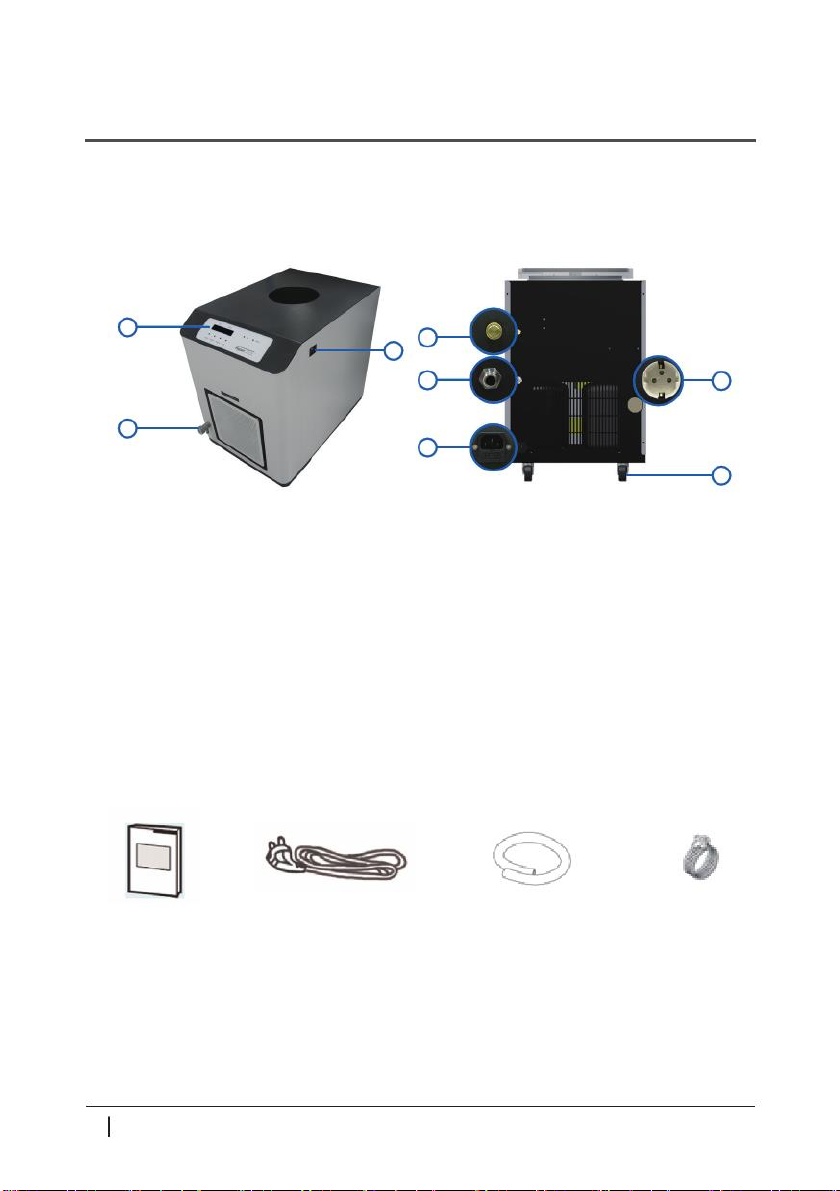
2.1 product composition
Front Back
1. Control panel 5. Vacuum hose connector
2. Waterspout 6. Vacuum release knob
3. Power switch 7. Vacuum pump power socket
4. Power socket 8. Moving wheel
2.2 Components
User manual AC Power Cord Vacuum Hose Clamp
※When ordering HyperCOOL, the above accessories are provided.
※Vacuum Pump is not included in the basic components and is sold separately.
HyperCOOL
16
7
8
5
4
3
2
6

2. Product composition and information
2.3 Technical Specifications
Model HC3055 HC3110
Ultimate Chamber Temp. (at RT) (℃) -55 -110
Chamber Volume (L) 4
Trap (Chamber) Size (Ø x L) 165 x 202
ICE Condensing Capacity (kg) 3
ICE Condensing Performance (kg / day) 2.5
Compressor 1/2HP 1/3HP x 2
Refrigerant R507 R507/R1150
Digital Readout Temperature, Time, Vacuum
Function
KEYLOCK, DEFROST, VACUUM, TIME
Actual vacuum sensing and display
(optional)
Power Requirement (Resting, VA) 2.0K 2.5K
Dimension (W x D x H, mm) 400 x 660 x 570
Weight (kg) 58 72
CE mark Yes

3. Product assembly and installation
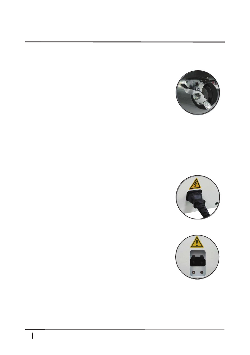
3.1 Open the product packing and fix the wheels
1. After purchasing the freeze dryer, open the packaged box
and check the components.
▶Components : Freeze dryer (Hypercool) / User manual
AC Power Cord / Vacuum Hose / Clamp
2. Place the machine horizontally on a flat surface,
and hold the wheel by lowering the wheel fixing lever at the bottom of the machine.
3.2 Power connection
1. Connect the AC power cord to the power socket located
at the bottom right of the rear of the main body,
and then connect the power plug to an outlet.
▶Please check the rated voltage to be used.
2. Raise the power switch located on the right side of the body
in the upper [ON] direction (↑).
HyperCOOL
8

3. Product assembly and installation
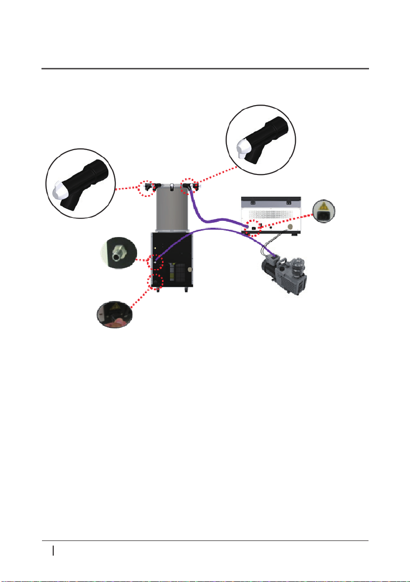
3.3 Operation according to HyperCOOL configuration
HyperCOOL : Independent operation
Open (vacuum state)
HyperCOOL -> Vacuum pump
Closed (vacuum released)
Pump power cord
connection
Vacuum hose connector
Vacuum pump
HyperCOOL
Vacuum pump power socket
Power socket
▶Check before operation
1. Make sure all vacuum valves are closed.
2. Place the chamber on the body. Make sure the chamber is well closed and
that all connections are secured.
3. Check if there is any water left in the drain.
4. Make sure that both the drain valve and the vacuum release knob are closed.
5. Check that the valve handle of the manifold plate is 'closed'.
Open (vacuum state) Closed (vacuum released)
6. When connecting a manifold or chamber, always make sure that all connections are tight.
9

3. Product assembly and installation
HyperCOOL (chamber) and vacuum centrifugal concentrator
Open (vacuum state)
HyperCOOL ->
Concentrator Power socket
Closed (vacuum released)
HyperCOOL ->
Vacuum pump
Pump power cord connection
Vacuum hose connector
HyperCOOL Vacuum pump
Power socket
▶Check before operation
Reference when HyperCOOL independent operation
▶Points to note when using integrated connection
When operating DEFROST in HyperCOOL, the concentrator must be used with the pump stopped.
(When the concentrator is stopped or operating below 1,000 rpm)
HyperCOOL
10

3. Product assembly and installation
HyperCOOL (chamber) and vacuum centrifugal concentrator
Power socket
HyperCOOL ->
Concentrator
Pump power cord connection
HyperCOOL ->
Vacuum pump
Vacuum hose connector
HyperCOOL Vacuum pump
Power socket
▶Check before operation
Reference when HyperCOOL independent operation
11

4. Usage and precautions
4.1 Control Panel
□DEFROST
▶This is a function to remove frost (ice) in the chamber.
▶Lamp ON : Defrost on / Lamp OFF :Defrost off
□VACUUM
▶This is a function for driving the pump and releasing vibration.
□TIME
▶The operation time can be set as "hour" and "minute", and operation is possible up to 999 hours
59 minutes.
▶Lamp ON : Time set mode / Lamp OFF : time set mode off
▶Lamp ON : Pump on/ Lamp OFF : Pump off
▶VACUUM button: Press for 3 seconds to check the vacuum value.
□KEY LOCK
-Basic Model: 0~760 Torr (Vacuum value below "0" is not displayed)
-Optional Pirani sensor : 0.001~760 Torr
▶Setting value change during operation. (set the Lock mode to prevent (DEFROST,VACUUM,TIME).)
▶Lamp ON : KEY LOCK set mode / Lamp off: Key LOCK set mode off
□AWO Lamp
▶This lamp allows you to check the temperature range in the chamber.
▶Lamp lighting/flashing range
□POWER Lamp
▶Lamp ON : Power on / Lamp off: Power off
HyperCOOL
Status Lamp changes HC3055 HC3110
Alarm Flashes every 5 second -20℃<
Flashes every 1 second Flashes every 5 second -20 ~ -50 ℃-20 ~ -90 ℃
Flashes every 5 second light on -50℃> -90℃>
12

4. Usage and precautions
4.2 Display
Temp display: It displays the current temperature,
and the unit is ℃.
Time display: It displays the operating time and is displayed
in hours and minutes..
Vacuum value display: Vacuum value is displayed
by pressing VACUUM button for 3 seconds.
▶Displayed up to 999 hours and 59 minutes.
4.3 DEFROST
The DEFROST function is used to remove frost or ice in the trap by using hot gas.
1. During operation, the DEFROST LED is turned off, and when the DEFROST button is pressed,
the LED lights up and the DEFROST function is activated.
▶When using the DEFROST function, first open the vacuum release knob to release
the vacuum in the trap for 1 minute to prevent water inflow into the pump,
and then press the DEFROST button.
2. When the DEFROST function is activated, ice can be removed by melting
between the Cold Trap chambers.
Removal of liquid inside the chamber!
If there is water due to melting ice in the chamber
after DEFORST operation, open the drain hole on
the front of the product to remove the water.
Open the valve handle by turning it counterclockwise.
13

4. Usage and precautions
4.4 VACUUM
Pressing the VACUUM button in the vacuum condition releases the vacuum condition
by introducing external air. It is a function to create a vacuum environment by removing the air
in the trap by pressing the VACUUM button in the vacuum release state.
1. Press the VACUUM button to create a vacuum environment in the trap.
▶The VACUUM LED blinks and the LED lights up when the vacuum pump is operating.
2. If you press the VACUUM button once during
operation of the vacuum pump, the operation of the
vacuum pump is terminated.
The vacuum is released by opening the vacuum release
knob or the valve on the manifold plate.
▶You can check the vacuum value by pressing the [VACUUM] button for more than 3 seconds.
- Basic Model: 0~760 Torr (Vacuum value below "0" is not displayed)
- Optional Pirani sensor : 0.001~760 Torr
Vacuum release speed regulation!
You can adjust the vacuum release speed by turning
the vacuum release knob on the back of the product.
▶Clockwise rotation: Reduces vacuum release speed
▶Counterclockwise rotation: Increases vacuum release speed
HyperCOOL
14

4. Usage and precautions
4.5 TIME
Up to 999 hours 59 minutes or continuous operation (0:00) can be set.
1. Press the [TIME] button once, use the ▲[DEFROST] and ▼[VACUUM] buttons to set the minute,
then press the TIME button once more to set the “hour”.
▶0:00 is continuous operation and TIME is counted up.
▶If you press and hold the DEFROST button in the TIME setting state, the minute value increases,
and after 59 minutes, the hour value increases gradually and rapidly.
(Increases in increments of up to 10 hours)
▶When canceling the set value, press KEYLOCK.
▶When the product is shipped, continuous operation (0:00) is set.
2. After entering the set value, press the TIME button to save the time and count down the time.
3. When the set time is over, End is displayed and a buzzer sounds.
▶Press the KEYLOCK, DEFROST, VACUUM or TIME button to stop the buzzer sound.
Time LED operation status by situation
▶LED OFF : Time count-up section during continuous operation (00:00)
▶LED Flashing : The section in which the TIME setting is changed
during operation or stop
▶LED ON : The section that operates during the set time after setting TIME
4.6 KEYLOCK
Execute the lock function.
1. If you press the KEYLOCK button during operation, the KEYLOCK LED turns on,
and all buttons except the KEYLOCK button cannot be input
2. To release KEYLOCK, press the KEYLOCK button again.
15

5. Maintenance
5.1 Inside the trap
1. If the inside of the trap is contaminated, clean it with a soft cloth moistened with soapy water
and wipe it with a dry cloth, taking care not to leave any moisture.
2. Do not use chemicals such as alcohol, benzene, benzole, etc.
3. Be careful not to scratch the surface when cleaning or moving.
▶If there is a flaw on the trap surface, there is a risk of rust.
▶If rust is formed by leaving it wet for a long time,
remove it with a neutral detergent and wipe it with a dry cloth.
5.2 Condenser dust removal
Remove dust periodically in order to maintain the refrigeration function of the condenser normally.
Be sure to turn off the power during this operation.
If foreign matter or dust is found
on the condenser surface, remove it.
It is separated by pulling
the front air suction plate with both hands.
HyperCOOL
16

6. Problem solving
6.1 Checklist before reporting a malfunction
If an error occurs in the freeze dryer, check the following before requesting a service center.
6.2 Error message
Before requesting repair, check the serial number on the label on the side of the device
and contact the service center.
Symptom Checklist
No power
Refer to 3.2 Power Connection, check the grounding part of the
outlet to see if the power plug is removed, and check the location of
the ON/OFF button of the power switch.
No vacuumMake sure that the silicone packing attached to the accessory is in
place.
Type Type Action
Error 1 Temp inside
the chamber
It appears when the temperature inside the chamber is outside the
normal allowable range.
Turn off the power and contact the service center.
Error 3 Comp1 temp
Appears when the Comp1 temperature is outside the normal allowable
range.
Turn off the power and contact the service center.
Error 4 Comp2 temp
Appears when the Comp2 temperature is outside the normal allowable
range.
Turn off the power and contact the service center. (Occurs only on
HC3110 products)
Error 5 Comp1 temp sensor Appears when the Comp1 temperature sensor does not operate
normally.
Error 6 Comp2 temp sensor Turn off the power and contact the service center. (Occurs only on
HC3110 products)
Error 7 Chamnber temp sensor
Appears when the Comp2 temperature sensor does not operate
normally.
(Occurs only on HC3110 products)
17

6. Problem solving
6.3 Etc
1. Be sure to follow the warnings and instructions on the label attached to the body.
2. Use genuine devices and parts from the designated place of purchase.
If you use other (unknown) equipment, the performance of the main unit may be degraded,
and you may not receive proper customer service.
3. The power is connected to the power socket at the bottom left of the back of the main body,
and disconnect the power cord to cut off the main body.
4. Do not open or disassemble this device at your discretion.
HyperCOOL
18

7.
V04AC02050-00
Valve Handle
V04AC02050-00
Valve Handle
V04AC02050-00
Valve Handle
V04AC02050-00
Valve Handle
V04RB12350-00
Rubber Valve Body
V04RB12350-00
Rubber Valve Body
V04RB12350-00
Rubber Valve Body
V04RB12350-00
Rubber Valve Body
V04CS12350-00
Connector (Valve)
V04CS12350-00
Connector (Valve)
V04CS12350-00
Connector (Valve)
V04CS12350-00
Connector (Valve)
V04AC00950-00
Manifold Extension-4
HC-MFE-4V
4-Valve Manifold Extension
HC-MFE-6V
6-Valve Manifold Extension
HC-MFB-6V
6-Valve Manifold Basic
HC-MFB-4V
4-Valve Manifold Basic
V07RB04350-00
Packing (manifold Plate)
V04RB12020-00
O-Ring-P285
V04AC00150-00
Manifold Plate (BOT)
V04RB00120-01
Packing (Chamber)
V04RB12120-00
Gasket
HC-CPB
HyperCOOL Acrylic Base
HC-CPB
HyperCOOL Acrylic Base
HC-CPB
HyperCOOL Acrylic Base
HC-CPB
HyperCOOL Acrylic Base
V04AC00750-00
Manifold-4
V04AC00650-00
Manifold-6
V04RB12250-00
0-Ring-AN024
V04RB12250-00
0-Ring-AN024
V04CS12450-00
Manifold Bar-300
V04CS12450-00
Manifold Bar-300
V04RB12250-00
0-Ring-AN024
V04RB12250-00
0-Ring-AN024
V04RB12250-00
0-Ring-AN024
V04RB12250-00
0-Ring-AN024
V04CS12550-00
Manifold Bar-200
V04CS12550-00
Manifold Bar-200
V04RB12250-00
0-Ring-AN024
V04RB12250-00
0-Ring-AN024
V04AC00850-00
Manifold Extension - 6
V04AC00150-00
Manifold Plate (BOT)
Accessories

HyperCOOL
7.
V04AC02050-00
Valve Handle
V04RB12350-00
Rubber Valve Body
V04CS12350-00
Connector (Valve)
V04AC00250-00
Manifold Plate (TOP)-8V
V07RB04350-00
Packing (manifold plate)
HC-CH300
Chamber (Ø300)
HC-CH300
Chamber (Ø300)
HC-CR25
Stainless Steel Rack
V04AC00220-00
Manifold Plate (TOP)-8V Assembly
V04AC00220-00
Manifold Plate (TOP)-8V Assembly
V04TR10450-00
Tray Pole - Center
V04TR10350-00
Tray Pole - Left
HC-CPB
HyperCOOL Acrylic Base
HC-CPB
HyperCOOL Acrylic Base
V07RB04350-00
Packing (manifold plate)
V04AC00150-00
Manifold Plate (BOT)
V04RB00150-00
Packing (Chamber)
V04TR10250-00
Tray Pole - Right
V04TR10150-00
Tray Frame Base
V04TR10050-00
Tray - 250
V04TR10550-00
Shelf - 250
Accessories
20
This manual suits for next models
1
Table of contents
Popular Air Conditioner manuals by other brands

Admiral
Admiral AW-05CM1FLU use and care manual

GE
GE AER05LX Owner's manual and installation instructions

Airwell-Fedders
Airwell-Fedders Thru-the-Wall Room Air Conditioner Installation instructions and owner's manual

TemperZone
TemperZone OPA 650RKTB Installation & maintenance

DeLonghi
DeLonghi PAC N135E instruction manual

Toyotomi
Toyotomi TID-1800HP Type A user guide