HYT TC-580 User manual

8110058000120
is the trademark of Hytera Communications Corp., Ltd.
2010 Hytera Corp., Ltd. All Rights Reserved.
Address: HYT Tower, Hi-Tech Industrial Park North, Beihuan
RD., Nanshan District, Shenzhen, China
Post:518057
http://www.hytera.cn
www.hytera.cn
L06774 X05031

1
Preface
Thank you for purchasing Hytera TC-580 portable radio. It
incorporates ergonomic design, and practical features such as
front panel programming and DTMF Encode & Decode. You can
conveniently customize radio settings and make calls.
To derive optimum performance from your radio, please read the
Safety Information Booklet and Owner’s Manual carefully before use.

2
Icon Information
The following icons are available through this manual:
Caution: indicates situations that could cause
damage to your radio.
Note: indicates tips that can help you make
better use of your radio.
Term Explanation
The following terms will appear through this manual:
Key Operation
Short press: to press a key and release it quickly.
Long press: to press and hold down a key for above 1.5
seconds.
Hold down: to press a key and remain holding it down.
User Mode
Refers to the mode entered after you turn on the radio
directly.
■
■
Manual Program Mode
Refers to the mode entered after you turn on the radio
with both PTT and SK2 held down for 1.5 seconds.
Zone
Zone is a group of channels, dedicated for you to orga-
nize channels.
Zone All
Includes all available channels.
DTMF
Dual-tone multi-frequency (DTMF) signaling is used for
making selective calls, calling party identification, call
alert and etc.
CTCSS/CDCSS
The signaling can help you prevent unwanted conversa-
tions at the same frequency.
PTT ID
PTT ID, namely radio identity, allows a radio with display
and the control center to identify the calling party.
■
■
■
■
■
■

3
Copyright Information
Hytera and CRS are registered trademarks of Hytera in
PRC and other countries and/or areas. Hytera retains
the ownership of its trademarks and product names. All
other trademarks and/or product names that may be
used in this manual are properties of their respective
owners.
The Hytera product described in this manual may
include Hytera computer programs stored in memory
or other media. Laws in the PRC and/or other countries
or areas preserve for Hytera exclusive rights for Hytera
computer programs. The purchase of this product shall
not be deemed to grant, either directly or by implication,
any rights to the purchaser with respect to Hytera
computer programs. Any Hytera computer programs
may not be copied, modified, distributed, decompiled,
or reverse-engineered in any manner without the prior
written consent of Hytera.
Disclaimer
Hytera endeavors to achieve the accuracy and com-
pleteness of this manual, but no warranty of accuracy or
reliability is given. All the specications and designs are
subject to change without prior notice due to continuous
technology development. No part of this manual may be
copied, modied, translated, or distributed in any man-
ner without the express written permission of Hytera.
If you have any suggestions or would like to learn more
details, please visit us at: http://www.hytera.cn.

4
RF Energy Exposure Compliance
Your radio is designed and tested to comply with a
number of national and international standards and
guidelines (listed below) regarding human exposure
to radio frequency electromagnetic energy. This radio
complies with the IEEE and ICNIRP exposure limits
for occupational/controlled RF exposure environment
at operating duty factors of up to 50% transmitting
and is authorized by the FCC for occupational use
only. In terms of measuring RF energy for compliance
with the FCC exposure guidelines, your radio radiates
measurable RF energy only while it is transmitting (during
talking), not when it is receiving (listening) or in standby
mode.
Your radio complies with the following of RF energy
exposure standards and guidelines
United States Federal Communications
Commission, Code of Federal Regulations; 47CFR
part 2 sub-part J
American National Standards Institute (ANSI)/
Institute of Electrical and Electronic Engineers
(IEEE) C95. 1-1992
Institute of Electrical and Electronic Engineers
(IEEE) C95. 1-1999 Edition
International Commission on Non-Ionizing Radiation
Protection (ICNIRP) 1998
Operational Instructions and Training Guidelines
To ensure optimal performance and compliance with
the occupational/controlled environment RF energy
exposure limits in the above standards and guidelines,
users should transmit no more than 50% of the time and
always adhere to the following procedures:
Transmit and Receive
To transmit (talk), push the Push-To-Talk (PTT) key; to
receive, release the PTT key.

5
FCC Licensing Information
Part 15 Compliance
This equipment has been tested and found to comply
with the limits for a Class B digital device, pursuant to
part 15 of the FCC Rules. These limits are designed to
provide reasonable protection against harmful interfer-
ence in a residential installation. This equipment gen-
erates, uses and can radiate radio frequency energy
and, if not installed and used in accordance with the
instructions, may cause harmful interference to radio
communications. However, there is no guarantee that in-
terference will not occur in a particular installation. If this
equipment does cause harmful interference to radio or
television reception, which can be determined by turning
the equipment off and on, the user is encouraged to try
to correct the interference by one or more of the follow-
ing measures:
Reorient or relocate the receiving antenna.
Increase the separation between the equipment and
receiver.
Co n n e ct th e e q u ipm e n t i nto a n o u t le t o n a
circuit different from that to which the receiver is
connected.
Consult the dealer or an experienced radio/TV
technician for help.
FCC Licensing Requirements
A license from Federal Communications Commission
is required prior to use. Your dealer will program each
radio with your authorized frequencies, signaling codes,
etc., and will be there to meet your communications
needs as your system expands. Contact your dealer for
more information.

1
Contents
Checking Items in the Package -------------------- 3
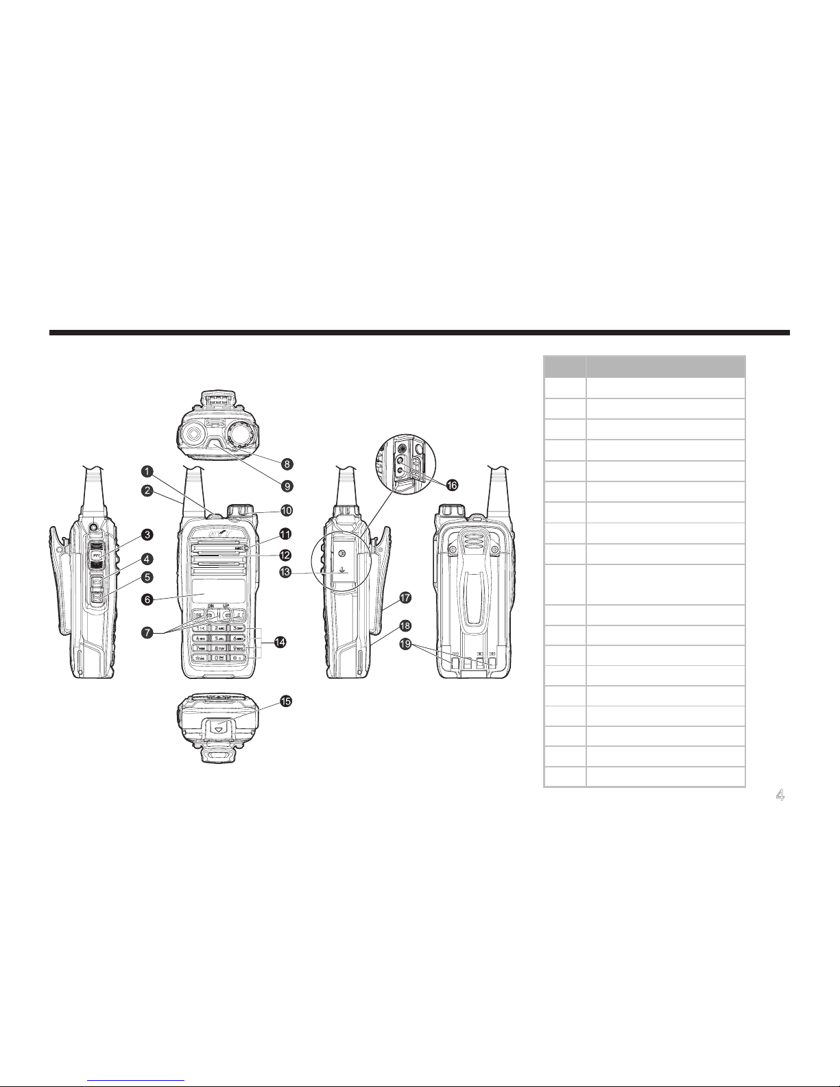
Radio Overview ---------------------------------------- 4
Radio Controls -------------------------------------------- 4
Programmable Keys ------------------------------------- 5
Before Use----------------------------------------------- 7
Charging the Battery------------------------------------- 7
Assembly and Disassembly---------------------------- 8
Status Indications -------------------------------------- 10
LCD Icons -------------------------------------------------- 10
LED Indicator ---------------------------------------------- 11
Basic Operations--------------------------------------- 12
Turning the Radio On/Off------------------------------- 12
Entering Power-on Password ------------------------- 12
Adjusting the Volume ------------------------------------ 12
Selecting a Zone------------------------------------------ 12
Selecting a Channel ------------------------------------- 13
Inputting a Frequency ----------------------------------- 13
Adjusting Power Level----------------------------------- 14
Transmitting/Receiving a Call ------------------------- 14
Locking/Unlocking the Keypad------------------------ 15
Menu Navigation --------------------------------------- 16
Call List------------------------------------------------------ 16
Zone --------------------------------------------------------- 16
Settings ----------------------------------------------------- 16
Scan --------------------------------------------------------- 19
Keypad Mode---------------------------------------------- 19
Functions and Operations --------------------------- 20
Time-out Timer (TOT) ----------------------------------- 20
Channel Scan --------------------------------------------- 20
Emergency ------------------------------------------------- 22
Quick Call--------------------------------------------------- 22
Home Channel -------------------------------------------- 23
Display Mode Switch ------------------------------------ 23
Keypad Mode Switch ------------------------------------ 24

2
Talk Around------------------------------------------------- 24
Monitor ------------------------------------------------------ 24
Squelch Off------------------------------------------------- 25
Compandor------------------------------------------------- 25
Scrambler--------------------------------------------------- 26
VOX ---------------------------------------------------------- 26
Whisper ----------------------------------------------------- 27
Reverse Display ------------------------------------------ 27
Signaling Introduction--------------------------------- 28
CTCSS/CDCSS------------------------------------------- 28
Dual Tone Multiple Frequency (DTMF) ------------- 28
Manual Program --------------------------------------- 30
CH Set------------------------------------------------------- 31
Zone Set ---------------------------------------------------- 34
Troubleshooting ---------------------------------------- 36
Care and Cleaning ------------------------------------ 38
Optional Accessories --------------------------------- 39
Appendix: Input Method------------------------------ 41
Contents

3
Please unpack carefully and check that all items listed below are received. If any item is missing or damaged, please
contact your dealer.
Checking Items in the Package
Radio Unit Battery Rapid-rate Charger Power Adapter (different P/N for
(for Li-Ion battery) different countries and areas)
Antenna Belt Clip Strap Owner’s Manual /Safety Information
Booklet
Note:
The above pictures are for reference only. Actual products may vary slightly.
The antenna may vary with different frequency bands. And the frequency band is marked on the label
of antenna; if not, please refer to the label on the radio for frequency band information.

4
Radio Overview
Radio Controls No. Part Name
1 Strap Hole
2 Antenna
3 PTT Key
4 SK1 (programmable)
5 SK2 (programmable)
6 LCD Display
7 Function Keypad
8 LED Indicator
9 TK (programmable)
10 Radio On-Off/Volume
Control Knob
11 Microphone
12 Speaker
13 Accessory Jack Cover
14 Numeric Keypad
15 Battery Latch
16 Accessory Jack
17 Belt Clip
18 Battery
19 Charging Piece

5
Programmable Keys
For enhanced convenience, you may request your
dealer to program the keys SK1, SK2, and TK as
shortcuts to the functions listed below:
No. Shortcut
Keys Description
1
Adjust
Power
Level
To adjust power level through
one button press.
2 Call 1
To quickly make a call to a pre-
dened user.
3 Call 2
4 Call 3
5 Call 4
6 Call 5
7Compan-
dor
For clear voice in noisy environ-
ments.
8
Display
Mode
Switch
To switch display of channel
information among channel
No., channel alias and channel
frequency.
9Emer-
gency
To summon help in emergent
situations.
Radio Overview
10 Home
Channel
To quickly switch to the Home
channel.
11 Keypad
Mode
To quickly switch keypad entry
among frequency, channel,
DTMF, or to disable it.
12 Monitor
To adjust the condition for incom-
ing signal match.13
Monitor
Momen-
tary
14 Squelch
Off To always unmute speaker no
matter whether carrier is present
or not.
15
Squelch
Off Mo-
mentary
16 Scan To receive signals on other chan-
nels.
17 Scrambler
To encrypt voice and thus protect
your conversations from eaves-
dropping.
18 VOX The radio can automatically be-
gin to transmit when you speak.

6
19 Whisper
The feature allows you to speak
quietly into the radio and still be
heard clearly.
20 Reverse
Display
To invert display contents 180
degrees.
21 Talk
Around
To directly communicate with
other radios.
Radio Overview
Note: Long and short press of a key can be a
different functions by your dealer.

7
Before Use
Charging the Battery
Use only the charger and battery specied by Hytera.
Charger LED can indicate the charging process.
Charge Diagram
Procedures
1. Connect the power adapter to AC source. See
arrow 1.
■
2. Plug the power adapter into the rear socket of the
charger. See arrow 2.
3. Place the radio with the battery attached, or the
battery alone, into the charger. See arrow 3.
4. The charging process initiates when LED glows red,
and is completed when LED glows green.
Charge Indicator
LED Indicator Charge Status
LED solidly glows red. Charging
LED solidly glows
orange. 90% charged
LED solidly glows
green. Idle or charge completed
When battery power runs low, the LED will ash red, and
the low-pitched tone will sound periodically. In this case,
please replace or charge the battery.
Note: To achieve optimal battery performance,
please charge the battery for 5 hours
before initial use.

8
Before Use
Assembly and Disassembly
Attaching the Antenna
Turn the antenna clockwise to fasten it.
To remove the antenna, rotate it counter-clockwise.
■
Note: Be sure to read the Safety Information
Booklet, to get necessary safety informa-
tion.
Attaching the Battery
1. Press the belt clip and slide the battery into the
radio’s slot.
2. Slightly press the bottom of the battery until a click
is heard.
To remove the battery, turn off the radio first. Then
press the belt clip, and slide the battery latch upward to
release the battery.
■

9
Attaching the Belt Clip
1. Remove the screws.
2. Align the screw holes on the belt clip with those on
the radio’s body, and then tighten the screws.
To remove the belt clip, loosen the screws.
Attaching Accessories
1. Open the accessory jack cover.
■
■
Before Use
2. Plug an accessory into the accessory jack, and then
tighten the screw.
To remove accessories, loosen the screw rst.
Caution: When you are using an external
accessory, waterproof performance of the
radio may get affected.

10
Status Indications
LCD Icons
Icon Name Icon Description
RSSI There is no signal;
There is signal for receiving;
Transmit Icon Transmission is in progress;
Scan Icons
Scanning is in progress;
Scanning pauses on a non-
priority channel;
Scanning pauses on Priority
Channel 1;
Transmit Power
Icons
The current channel is oper-
ating at low power;
The current channel is oper-
ating at high power;
Battery Strength
Icons More bars indicate more bat-
tery power;
Home Channel
Icon
The radio stays on a Home
channel;
Monitor Icon Monitor function is active;
Squelch Icon Speaker is unmuted;
VOX Icon VOX function is active;
Keypad Lock
Icon The keypad is locked;
Whisper Icon Whisper function is active;
Scrambler Icon Scrambler function is active;
Compandor Icon Compandor function is ac-
tive;
Emergency Icon
The Emergency function is
active or an emergency alarm
is received;
Talk Around Icon Talk Around function is ac-
tive;
CTCSS Icon CT TX/RX CTCSS is pro-
grammed on current channel;
CDCSS Icon DT TX/RX CDCSS is pro-
grammed on current channel;
DTMF Icon DF TX/RX DTMF is programmed
on current channel.

11
Status Indications
LED Indicator
The top LED indicator will help you easily identify the
current status of your radio.
LED Indicator Radio Status
Red LED glows. Transmitting
Red LED ashes. Low battery alert
Green LED glows. Receiving
Green LED ashes. Scanning
Orange LED glows. A call is transmitted (within
the Auto Reset Time)
Orange LED ashes
slowly.
A call is received (within the
Auto Reset Time)
Orange LED ashes
rapidly. A call is missed

12
Basic Operations
Turning the Radio On/Off
Rotate the Radio On-Off/Volume Control knob
clockwise/counter-clockwise until a click is heard to turn
the radio on/off.
Entering Power-on Password
You may go to the menu “Settings->PowerOn PSW” to
set the password on or off. See PowerOn PSW on page
18 for more details.
After you input the password, press to confirm.
Then a power-on alert tone will sound, and the home
screen will appear. However, if the password is incor-
rect, the display will show “Error”, prompting you to enter
the password again.
Adjusting the Volume
You may adjust call volume through the knob. Rotate
the knob clockwise to increase the volume, or counter-
clockwise to decrease the volume.
To adjust volume for alert tones or warning tones, go to
the menu “Settings->Alert VOL / PowerOn VOL / Key
VOL / Warning VOL” (See Settings on page 16 for more
details).
Selecting a Zone
The radio supports up to 32 zones. You may choose
to operate in a single zone, or choose Zone All so you
Note:
When PowerOn PSW is set on, you will
be required to input the password to turn
on the radio.
The password is programmable by your
dealer, and may contain up to 8 digits.

13
can access all the available channels. You may select a
zone through any of the following methods:
You may quickly toggle to your desired zone,
through press of the programmed Zone Up or
Zone Down key; or
Go to the menu “Zone”, press / to select
your desired zone, and then press to conrm.
Selecting a Channel
The radio supports up to 256 channels. You may select
a channel through any of the following methods:
Press / to select your desired channel; or
When the keypad input mode is set to Channel,
directly enter the channel No., and then press
Note: You may include channels in a zone
in Manual Program mode, or ask your
dealer to include them in a zone.
to switch to the channel (see Keypad Mode
Switch on page 24 for more details); or
Press the programmed Home Channel key to
quickly switch to the Home channel (See Home
Channel on page 23 for more details).
Inputting a Frequency
You can manually input a desired frequency within the
frequency band of your radio, to transmit and receive
calls. Operations:
1. Select Frequency from the menu “Keypad Mode”,
and press .
2. Return to the home screen, input your desired
frequency through the keypad, and press .
By way of illustration, to input fre-
quency 365.65000MHz, just press
the following keys one by one:
+ + + + + +
Basic Operations

14
Then the entered frequency will appear on the home
screen, and you can transmit and receive on the fre-
quency.
Basic Operations
Note:
The entered frequency will be saved if you
turn the radio off and back on, but will not be
saved if you change channel. It will be used
for both transmitting and receiving. However,
other channel parameters such as TX power
and channel spacing will remain unchanged.
To save the frequency permanently or to cus-
tomize other channel parameters, enter the
Manual Program mode and go to “CH Set” (See
CH Set on page 31 for more details).
If you enter a frequency out of the frequency
band, the LCD will display “Out of Range”. If
the entered frequency is not compliant with
the rule, the radio will display a valid frequency
closest to it.
This function may not be available in certain
countries or regions. Please contact your local
dealer for more information.
Adjusting the Power Level
Generally, we recommend you to adopt low power for
battery saving. However, if you cannot communicate
with radios located at a distant place with low power,
please select high power. Operations to change power
level:
Press the programmed Adjust Power Level key
to switch between high and low; or
Enter the Manual Program mode, and go to “CH
Set->Option Items->Power Level”, to select high
or low power (See Power Level on page 33 for
more details).
The home screen shows the icon for high power, and
for low power.
Transmitting/Receiving a Call
To transmit a call, press and hold down the PTT, and
speak into the microphone. During transmitting, the LED
solidly glows red, and the icon appears on the dis-
play.
Other manuals for TC-580
3
Table of contents
Other HYT Portable Radio manuals