Hytorc HY-Air Series User manual

Hydraulic unit
JetPro-S-Air, HY-Air, HY-Twin-Air
English translation of the original German operating
instructions
for qualified and authorized operating personnel
Status 6/2019
Always store these operating instructions together at the hydraulic unit. Ensure that the operating instructions
are available for the qualified and authorized operating personnel. Read and comply with the operating
instructions.
Non-observance can lead to injury and possibly death.

Publisher
HYTORC Technologies GmbH
Kleinbeckstr. 3–17
45549 Sprockhövel, Germany
Tel.: +49 (0) 23 24-90 77-0
Fax: +49 (0) 23 24-90 77-99
info@hytorctech.com
www.hytorctech.com
Document no.
BA-0060-EN00
Revision no.
00
Document type
Operating instructions
Issue date
6/7/2019
Copyright
© 2019, HYTORC Technologies GmbH
All rights, including those of reprinting and reproduction of any parts of
this document and its translation, are reserved by the publisher.
No part of this document may be reproduced in any form or copied
using electronic reproduction systems without the written consent of
the publisher.
We reserve the right to make technical changes in the course of further
development.

Table of contents
Notes concerning this manual and the manufacturer ............................................6
Keep the manual available .............................................................................................6
Design features of this manual.......................................................................................6
Referenced documents...................................................................................................7
Manufacturer's address ..................................................................................................7
Person responsible for documentation...........................................................................8
Warranty and liability ......................................................................................................8
Safety........................................................................................................................9
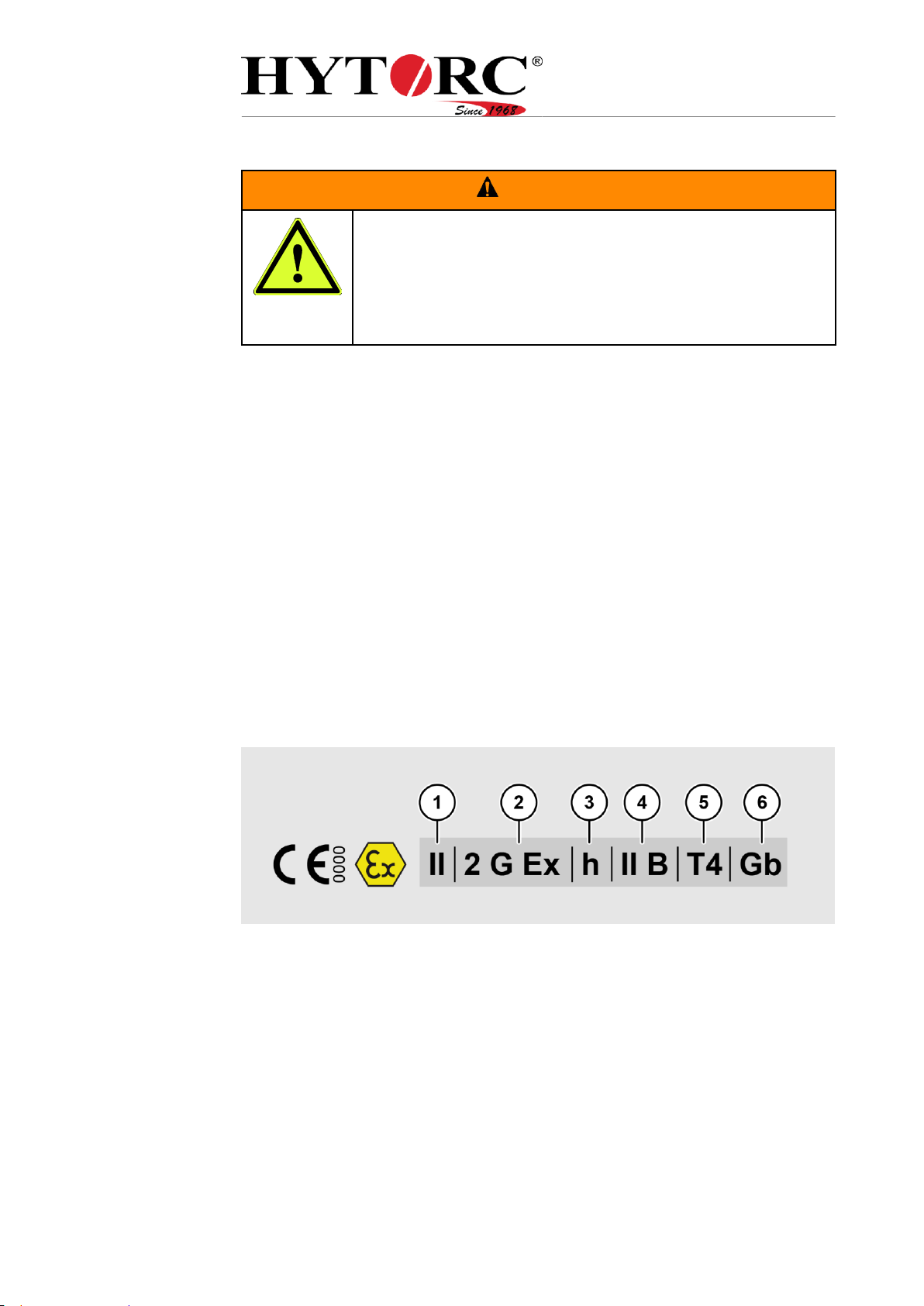
ATEX marking.................................................................................................................9
Equipment group (1).............................................................................................9
Equipment category (2)......................................................................................10
Ignition protection type (3)..................................................................................10
Explosion group (4) ............................................................................................10
Temperature class (5) ........................................................................................10
Equipment protection level (6)............................................................................11
ATEX marking of the unit....................................................................................11
Responsibilities of the operating company...................................................................11
Persons at particular risk..............................................................................................12
Qualification of personnel.............................................................................................12
Connecting the Compressed Air Supply ............................................................12
Tool connection ..................................................................................................12
Setting pressure/torque......................................................................................13
Assessing the state of the unit ...........................................................................13
Carrying the unit .................................................................................................13
Ban of unauthorized conversions .................................................................................14
Personal protective equipment.....................................................................................14
Basic safety information................................................................................................15
Preventing serious injury or death......................................................................15
Preventing explosion hazards ............................................................................15
Preventing burns from oil and hot surfaces........................................................15
Preventing poisoning..........................................................................................15
Preventing bone fractures and crushing.............................................................16
Preventing eye damage......................................................................................16
Preventing skin irritation.....................................................................................16
Preventing material damage ..............................................................................16
Intended use.................................................................................................................17
Ambient conditions .......................................................................................................17
Design characteristics of warning information..............................................................18

Design of information about property damage .............................................................19
Warning and information signs.....................................................................................20
Description............................................................................................................. 22
Directional data.............................................................................................................23
Overview front right.......................................................................................................24
Overview front left.........................................................................................................25
Layout...........................................................................................................................25
Display and operating elements ...................................................................................26
Pressure gage....................................................................................................26
Couplings............................................................................................................26
Remote control for manual version ....................................................................27
Remote control for semi-automatic version........................................................28
Torque valve.......................................................................................................29
Maintenance unit................................................................................................30
Type plate.....................................................................................................................30
Available accessories...................................................................................................31
Workspaces and positions............................................................................................31
Purpose and function....................................................................................................32
Unpacking and checking the delivery................................................................... 33
Unpacking.....................................................................................................................33
Checking package and condition..................................................................................33
Storing the unit ...................................................................................................... 34
Moving the unit ...................................................................................................... 35
Commissioning the unit ........................................................................................ 36
Initial commissioning.....................................................................................................36
Daily commissioning.....................................................................................................38
Tool connection..................................................................................................38
Connecting the Compressed Air Supply ............................................................41
Bleeding the screw system (generator, hose, tools)..........................................41
Check oil level ....................................................................................................42
Checking functioning of the manometer.............................................................43
Performing a test run....................................................................................................43
Operating the unit.................................................................................................. 44
Changing tools..............................................................................................................44
Setting the pressure......................................................................................................48
Performing a screwing process ....................................................................................49

After use .................................................................................................................50
Decommissioning the unit.....................................................................................52
Servicing the unit ...................................................................................................53
Maintenance schedule..................................................................................................53
Changing the hydraulic oil ............................................................................................54
Filling the Maintenance Unit’s Oiler..............................................................................57
Cleaning the unit ....................................................................................................58
Remedying faults or malfunctions ........................................................................59
Table of faults ...............................................................................................................59
Disposal..................................................................................................................63
In the USA.....................................................................................................................63
In Europe ......................................................................................................................64
Technical specifications ........................................................................................65
HY-Air ...........................................................................................................................65
JetPro-S-Air ..................................................................................................................66
HY-Twin-Air...................................................................................................................66

Notes concerning this manual and the
manufacturer
6
Notes concerning this manual and the
manufacturer
These instructions help you to use the following hydraulic units safely:
JetPro-S-Air
HY-Air
HY-Air-2
HY-Air-SA
HY-Air 2-SA
HY-Twin-Air
These hydraulic units are hereinafter referred to as “unit(s)”.
Keep the manual available
These operating instructions are a part of the unit. Make sure that the
operating instructions are always accessible for the user at the site and are in
legible condition. Enclose the operating instructions when you sell the unit or
transfer it in any other way.
Design features of this manual
Various elements of these operation manual have fixed design characteristics.
These allow you to easily distinguish the following elements:
Normal text
Lists
Action steps
References to headers are set in quotation marks.
‘Labels’ of switches or other elements are set in inverted commas.
Table titles are set in bold.
Tips. Contains additional information.

Notes concerning this manual and the
manufacturer
7
Referenced documents
WARNING
Risk of injury from non-compliance with the applicable
documentation.
Prior to working with the unit, read all applicable
documents and comply with them.
These can be found in the documentation folder of the unit.
More information, instructions and details about the unit components can be
found in the documentation from the respective manufacturers. These
documents are regarded as a part of these instructions. Store these
documents together with this manual. Hand over these documents when
selling the unit or passing it on in other ways.
Referenced documents are the following document types in particular:
operating instructions
assembly instructions
maintenance or repair instructions
wiring diagrams
terminal diagrams
hydraulic diagrams
safety data sheets
drawings
spare parts lists
declarations of conformity or declarations of incorporation
ex-protection document of the operator
Observe and follow the information from the referenced documents.
These can be found in the documentation folder of the unit.
Manufacturer's address
HYTORC Technologies GmbH
Kleinbeckstr 3–17
45549 Sprockhövel
Germany
Telephone: +49 (0) 23 24-90 77-0
Fax: +49 (0) 23 24-90 77-99
E-Mail: info@hytorctech.com
Web: www.hytorctech.com

Notes concerning this manual and the
manufacturer
8
Person responsible for documentation
HYTORC Technologies GmbH
Michael Westermann
Kleinbeckstr 3–17
D-45549 Sprockhövel
Germany
Warranty and liability
In general our General Terms and Conditions apply. Warranty and liability
claims for personal injury or property damage are always excluded if they are
due to one or more of the following causes:
Improper use of the unit
Improper transport, installation, commissioning, operation and maintenance
of the unit
Ignoring the instructions in this manual
Ignoring the hazard notices on the unit
Unauthorized modifications of the unit
Inadequate monitoring of components which are subject to wear.
Incorrectly executed repairs
Disasters caused by outside intervention or an act of God.

Safety
9
Safety
WARNING
Severe injuries or death caused by accidents due to
disregard of the instructions in this guide.
In particular the failure to observe the instructions in the
Chapter on Safety, can lead to accidents.
Read and follow all instructions in this manual before you
begin working with or on the unit.
In addition to the notes in these operating instructions, also follow, in any
case, the statutory and other regulations, e.g.:
Accident prevention regulations
Regulations for safe and professional work
The applicable on-site regulations for explosion protection and fire protection
ATEX marking
The ATEX marking contains notes on the permissible use of the unit in
potentially explosive atmospheres. The following information is displayed:
Equipment group (1)
Equipment category (2)
Ignition protection type (3)
Explosion group according to DIN EN ISO 80079-36: 2016, DIN EN ISO
80079-37: 2016 (4)
Temperature class (5)
Equipment protection level (EPL) (6)
Equipment group (1)
Equipment that is intended for operation in a potentially explosive atmosphere
is classified into two groups. Group I includes equipment that is used in mines
susceptible to firedamp, e.g. in coal mines. The unit belongs to equipment
group II and can therefore be used in all potentially explosive areas except for
mining.

Safety
10
Equipment category (2)
Equipment category II comprises equipment that was designed in such a way
that ensures a high level of safety if the equipment is used as intended with
the prescribed parameters. Equipment of this category can be used in areas
where a potentially explosive atmosphere of gases, vapors, mists or dust/air
mixtures occurs occasionally. This is indicated with the letter G. Equipment of
category III is also included if it is likely that a potentially explosive atmosphere
will only occur rarely or for a short period of time. The unit falls under
equipment category II. Equipment of this category may only be used in zones
1 and 2 and/or zones 21 and 22.
Ignition protection type (3)
The ignition protection type represents the design principle followed in the
unit’s development with regard to explosion protection. The ignition protection
type “h” stands for “constructional safety” of non-electrical equipment.
Constructional safety means that constructional measures have been taken to
reduce hazards caused by ignitable temperatures or sparks to a very low level.
Explosion group (4)
Equipment of group II can also be classified according to the type of
potentially explosive atmosphere where the equipment may be used. The
subgroups IIA, IIB and IIC are used for this purpose. This classification is
based on the maximum experimental safe gap (MESG) and the minimum
ignition current ratio (MICR) of the gas mixture.
Temperature class (5)
Flammable gases and vapors are split into different temperature classes
according to their level of flammability (see table). The maximum surface
temperature of a piece of electrical equipment must always be below the
ignition temperature of the gas, vapor or air mixture where it is used.
Equipment that meets the requirements of a higher temperature class (e. g.
T5) is naturally also permitted for applications that require a lower temperature
class (e. g. T2 or T3).
Temperature -
class
Ignition temperature of gases
and vapors in °C
Maximum surface temperature
of equipment in °C
T1
> 450
450
T2
> 300 to 450
300
T3
> 200 to 300
200
T4
> 135 to 200
135
T5
> 100 to 135
100
T6
> 85 to 100
85

Safety
11
Equipment protection level (6)
The abbreviation “EPL” stands for “equipment protection level”. According to
the 2007 issue of IEC 60079-0, equipment for potentially explosive areas is
classified into three different protection levels:
EPL Ga or Da:
Equipment with a “very high” protection level for use in potentially explosive
areas which do not represent an ignition hazard in normal operation or in the
event of foreseeable or rare faults / malfunctions.
EPL Gb or Db:
Equipment with a “high” protection level for use in potentially explosive areas
which do not represent an ignition hazard in normal operation or in the event
of foreseeable faults / malfunctions.
EPL Gc or Dc:
Equipment with an “increased” protection level for use in potentially
explosive areas which do not represent an ignition hazard in normal
operation and which are provided with several additional protective
measures to prevent the risk of ignition in the event of commonly
foreseeable faults in the equipment.
ATEX marking of the unit
According to DIN EN ISO 80079-36. 2016, Section 11:
EX II 2 G Ex h IIB T4 Gb
This ATEX marking is valid for the following types of HY-Air hydraulic unit:
JetPro-S-Air
HY-Air
HY-Air-2
HY-Air-SA
HY-Air 2-SA
HY-Twin-Air
Responsibilities of the operating company
The operator must ensure that all accident prevention regulations are
complied with.
The operator must ensure that only qualified and authorized operating
personnel performs work on and with the unit.
The operator must ensure that the unit is grounded in accordance with the
applicable standards and regulations.

Safety
12
Persons at particular risk
The following groups of persons must not be granted access to the unit as
they might sustain serious or lethal injuries:
children
persons with physical or mental limitations
persons under the influence of drugs and medication
persons under the influence of alcohol
unauthorized persons, e. g. pedestrians
People without the qualifications specified in the following section.
Qualification of personnel
These operating instructions are addressed to qualified and authorized
operating personnel.
The following sections list the necessary qualification for each activity on or
with the unit.
Connecting the Compressed Air Supply
The operating personnel must have the following knowledge and experience:
Teaching and training received for the work.
Knowledge of the fact that improper operation, maintenance and repairs can
cause accidents.
Ability to assess hazards that may arise from compressed air.
Ability to assess hazards that may arise from the high-pressure components.
Ability to assess hazards that may arise from noise and heat.
Ability to detect leaks.
Ability to handle screw couplings to connect a compressed air supply to the
unit.
Ability to set a predetermined pressure on the unit’s maintenance unit.
Tool connection
The following skills and experience are required for the operating personnel:
have been taught and trained for the work
know that improper operation, maintenance and repairs can cause accidents
can assess risks and environmental damage that could be caused by
hydraulic oil
can assess risks that may arise from the high pressure components
can asses hazards that arise from noise and heat
can detect leaks
can handle screw couplings to connect tools to the unit
can assess hazards that may arise from potentially explosive atmospheres.

Safety
13
Setting pressure/torque
The following skills and experience are required for the operating personnel:
have been taught and trained for the work
know that improper operation, maintenance and repairs can cause accidents
can assess risks that may arise from the high pressure components
can asses hazards that arise from noise and heat
can set a predetermined pressure on the unit
Assessing the state of the unit
The operating personnel must have the following knowledge and experience:
Teaching and training received for the work.
Knowledge of the fact that improper operation, maintenance and repairs can
cause accidents.
Ability to assess hazards that may arise from compressed air.
Ability to assess hazards and environmental damage that may arise from
hydraulic oil.
Ability to assess hazards that may arise from the high-pressure components.
Ability to assess hazards that may arise from noise and heat.
Ability to detect errors in the unit’s condition by performing a visual
inspection prior to commissioning.
Leaks
Kinks in pneumatic hoses
Kinks in hydraulic hoses
External damage to pneumatic hoses
External damage to hydraulic hoses
Incorrectly set pressure on the maintenance unit
Incorrect fill level in the unit
can assess hazards that may arise from potentially explosive atmospheres.
Carrying the unit
The following skills and experience are required for the operating personnel:
have been taught and trained for the work
can asses hazards that arise from improper carrying
know that, with a weight of 25 kg, the unit is only permitted to be carried with
the help of a second person.

Safety
14
Ban of unauthorized conversions
Unauthorized conversions or changes on the unit will void the warranty and
invalidate the approval for explosive atmospheres.
Unauthorized conversions or changes on the unit may lead to serious or even
lethal injuries. This applies in particular to changing and altering safety
devices.
Never bypass or shunt any safety devices.
Personal protective equipment
Feet may be crushed when moving the unit.
Wear safety shoes with steel toe caps.
Slipping and thereby risk of fractures when performing hydraulic work is
possible!
Wear safety shoes with non-slip soles.
Skin irritation and eye damage when in contact with hydraulic oil and hydraulic
components is possible!
Wear oil resistant nitrile gloves and chemical-resistant goggles.
Burns on contact with hot fluids and components are possible!
Wear protective gloves against thermal risks.
Cuts and abrasions of the skin on sharp-edged components are possible!
Wear protective gloves against mechanical risks.
Hearing impairments while unit is running are possible!
In areas with high noise wear hearing protection.
Risk of poisoning possible in poorly ventilated rooms! The unit may overheat.
In this case, oil mist and oil vapors can form.
If this is the case, wear a respirator.
In addition, observe and follow the operator's instructions on personal
protective equipment.

Safety
15
Basic safety information
Preventing serious injury or death
Severe injury or death caused by failure of tools or hoses. Tools or hoses that
do not match the tool and hose specifications may fail.
Only use tools and hoses, which the manufacturer of the unit allows as an
accessory.
Preventing explosion hazards
Connecting tools to or changing tools at the unit in a potentially explosive
atmosphere can lead to serious injury or death.
Only connect tools to the unit in areas where there is no potentially
explosive atmosphere.
Only change tools at the unit in areas where there is no potentially explosive
atmosphere.
Maintaining the unit in a potentially explosive atmosphere can lead to serious
injury or death.
Maintain the unit only in areas where there is no potentially explosive
atmosphere.
Preventing burns from oil and hot surfaces
During and after operation, burns on metallic surfaces or from hydraulic oil are
possible.
When working on or with the unit wear protective gloves against thermal
risks.
Preventing poisoning
The unit may overheat. In this case, oil mist and oil vapors can form.
Make sure there is sufficient ventilation.
In poorly ventilated areas and upon formation of oil mist and oil vapors,
wear a respirator.
Switch the unit off when it overheats.
Allow the unit to cool down.
With the help of a non-contact infrared thermometer, ensure that the unit is
cooled down to 25 °C (77 °F).
Check the unit for possible damage.
Have the unit repaired, if damaged, by qualified personnel before
recommissioning.
When fluids leak, proceed as follows:
Wear temperature- and media-resistant gloves.
Take up liquid spills immediately with a suitable binding agent and a rag.
Dispose of the binding agent and rag environmentally correct.

Safety
16
Preventing bone fractures and crushing
Bone fractures and crushing possible. An unstable set-up can lead to the unit
toppling over.
Risk of slipping on leaked liquids and therefore of bone fractures!
Never reach into moving parts.
Always set up the unit on a flat, solid and stable base.
Secure the unit and tools against falling.
Secure the unit against unintended movement on site by locking the rollers.
Wear safety shoes with steel toe caps when moving the unit.
Wear safety shoes with non-slip soles when working on hydraulics.
Clean up liquid spillages.
Preventing eye damage
At pressures of more than 700 bar (10,000 psi) and operating the unit outside
of the tool and tubing specifications can lead to bursting of the hydraulic hoses
and spraying of hydraulic oil.
Make sure that the permissible pressure defined by the manufacturer is not
exceeded.
Observe the tool and hose manufacturer's specifications.
Observe and follow the operating instructions of the tools and hose
specifications.
Wear chemical-resistant goggles.
Preventing skin irritation
Contact with hydraulic oil may cause skin irritation.
Always provide a strong and tight connection between the unit and hydraulic
tools.
Wear nitrile gloves at work where you might come in contact with hydraulic
oil.
Make sure that the permissible pressure defined by the manufacturer is not
exceeded.
Observe the tool and hose manufacturer's specifications.
Observe and follow the operating instructions for the hydraulic tool.
Preventing material damage
Avoid soiling the couplings by installing the protective caps and protective
plugs when the couplings are not in use.
Always set the hydraulic tool down safely.

Safety
17
Intended use
The unit is used exclusively for driving hydraulic assembly tools for screws and
nuts in the commercial sector. With the screwing assembly tool, screw
connections can be loosened or tightened with a predetermined torque.
Intended use also includes observing and following all instructions in this
manual, especially the safety instructions. Any other use is considered to be
improper and will void the warranty and liability claims.
The unit must be properly grounded before commissioning.
The unit may be used with a connected screwing tool in potentially explosive
areas in accordance with its marking. The screwing tool and the hoses used
must be approved for use in potentially explosive areas by the manufacturer.
Ambient conditions
Make sure that the unit is used under the following environmental conditions:
Temperature range: +1 °C to +40 °C (34 °F to 104 °F)
Non-condensing humidity
Make sure that the unit is stored and transported under the following
environmental conditions:
Temperature range: –30 °C to +60 °C (–22 °F to 140 °F)
Non-condensing humidity

Safety
18
Design characteristics of warning information
DANGER
Sections with the word DANGER warn of imminent
dangerous situations that lead to death or serious injury.
WARNING
Sections with the word WARNING warn of imminent
dangerous situations that may lead to death or serious injury.
CAUTION
Sections with the word CAUTION warn of dangerous
situations that may lead to minor or moderate injuries.
Special symbols may be used in the warnings, in addition to the general
danger signs. These symbols indicate the possible danger. The meanings of
the individual symbols are found in the following section.

Safety
19
Explanation of symbols
Slipping hazard from leaked media
Burning hazard, scalding hazard
Risk of explosion in potentially explosive areas
Risk of eye damage due to splashing liquid
Risk of explosion and explosive media discharge
Design of information about property damage
ATTENTION!
These notes warn of situations that can lead to property
damage and limited functionality.

Safety
20
Warning and information signs
Make sure that all warnings and signs attached to the unit are clearly visible
and legible.
Replace damaged or lost warnings and signs immediately.
The following labels are affixed to the unit:
Warning or information sign
Meaning or explanation
Change the oil as required or after every major
application.
Use oil of Class 46.
The remote control may only be operated by the
tool user.
Recommendation of the manufacturer for seals
and other critical applications:
When using four tools simultaneously.
Reduce the number of cycles per workpiece
and ensure in this way a more accurate
pretension force.
Set the pressure or torque here.
Always set the pressure from low to high
pressure.
Switch off the unit when not in use.
This manual suits for next models
6
Table of contents
Other Hytorc Water Pump manuals
Popular Water Pump manuals by other brands

Hydromatic
Hydromatic SKV50M1 Installation and service manual

Carver Pump
Carver Pump G2S Installation, operation and maintenance instructions

Crane
Crane DEPA DL Series Operating and installation instruction

CountyLine
CountyLine CLA200 owner's manual

Pentair Jung Pumpen
Pentair Jung Pumpen DKG instruction manual

Stihl
Stihl SR 320 Assembly instructions

TLV
TLV CP-N instruction manual

EINHELL
EINHELL BG-WW 1038 N Original operating instructions

Siccom
Siccom FLOWATCH VISION DUO manual

GORMAN-RUPP
GORMAN-RUPP 14A2-B Installation, operation and maintenance manual

Grundfos
Grundfos DDI 222 Installation and operating instructions

Piusi
Piusi E120 Use and maintenance manual