Hytorc JETPRO-S 115/230 User manual

HYDRAULIC PUMP
OPERATIONS MANUAL
3rd. Edition: Mar. 2015


This manual applies to all pumps in the Hydraulic Pump Product Families. It is
recommended the manual is kept up-to-date by checking the edion and date code at
the boom of this page by ulizing the HYTORC website and downloading a copy of the
most recent edion as needed.
HYTORC Corporate Headquarters
333 Route 17 North
Mahwah, NJ 07430, USA
Noce: The informaon contained in this document is subject to change without noce. HYTORC
makes no warranty of any kind with regard to this material, including but not limited to, the implied
warranes of merchantability and tness for a parcular purpose. HYTORC shall not be liable for
errors contained herein or for incidental or consequenal damages in connecon with the furnishing,
performance, or use of this material. It is further recomended that the end-user or repair technician
insure they have obtained and are familiar with the latest revision of the manual for the equipment
outlined in this document.
Restricted Rights Legend: Use and duplicaon of the informaon contained within this manual is
limited to the purchaser, end user, or licensed Hytorc representave. It is recommended that proper
training for the equipment outlined in this manual be conducted by a HYTORC authorized training
representave for any person who is operang or repairing the equipment outlined in this document.
Modicaon, or disclosure by any other agency or representave is strictly forbidden.
Product Modicaons: Hytorc Corporaon DOES NOT ALLOW any of the products listed in this manual
to be modied by any end user without excepon. Should an applicaon require a modicaon to the
tool, or any of the standard accessories please consult with your local HYTORC representave and they
will be able to obtain the assistance for any modicaon that may be required.
Copyright © 2015 by HYTORC Division UNEX Corporation. All rights reserved.
Reproducon, adaptaon, or translaon without prior wrien permission is prohibited, except as
allowed under the copyright laws.
3rd. Edion. Printed in USA. March 2015
Complies with standards publicaon BS EN 82079-1:2012
HYDRAULIC PUMPS PRODUCT FAMILY:
JETPRO-S 115/230, HYSTREAM 115/230,
HY-115/230, HY-115-FA1, HY-115-FA4,
BigJet 18-400, HY-AIR
EN, EN-ISO, ISO Standards:
For a complete EC declaraon of conformity
or if you require any further assistance please
contact your local HYTORC representave or
1-800-FOR-HYTORC (1-800-367-4986) or on
the web at www.hytorc.com.
EN 982:2009
EN 61310-2:2008
EN 61310-3:2008
ISO 3744:2011
EN ISO 12100-1:2011
EN ISO 12100-2:2011
EN ISO 14121-1:2007
EN ISO 11148-6:2012

STAY SAFE
THANK YOU FOR PURCHASING THIS REVOLUTIONARY TORQUE/TENSION SYSTEM
PLEASE CALL YOUR HYTORC REPRESENTATIVE TO SCHEDULE A FREE TRAINING THAT WILL
HELP YOU GET THE MOST OUT OF THIS ADVANCED BOLTING SYSTEM.
OPERATING CD: Please show the enclosed CD to your staff before each tool use to familiarize them
with the tools.
FREE SAFETY TRAINING: To ensure safe operation, please request the FREE Safety Training
before use by calling your local HYTORC Representative 1-800-367-4986 or www.hytorc.com.
We recommend safety training every 6 months. These trainings are free of charge. Just call us.
PLEASE READ THE SAFETY INSTRUCTIONS HEREIN.
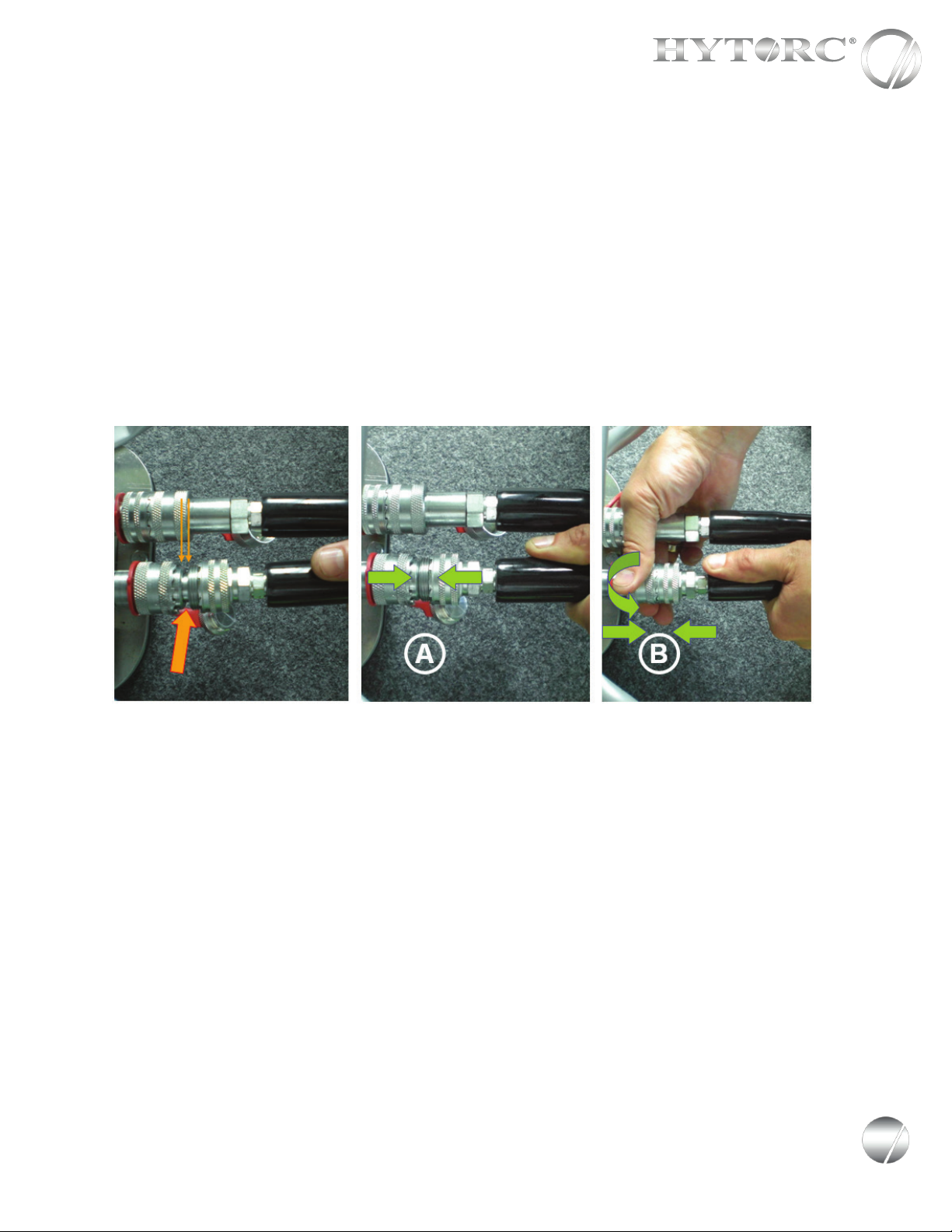
SYSTEM INSPECTION: Before any use, please inspect the entire tool system, including hoses,
gauge, sockets and backup wrenches. Do not use kinked hoses, oversized or heavily worn sockets,
backup wrenches, damaged tools, pumps, connectors, or gauges. Connect system to operate from
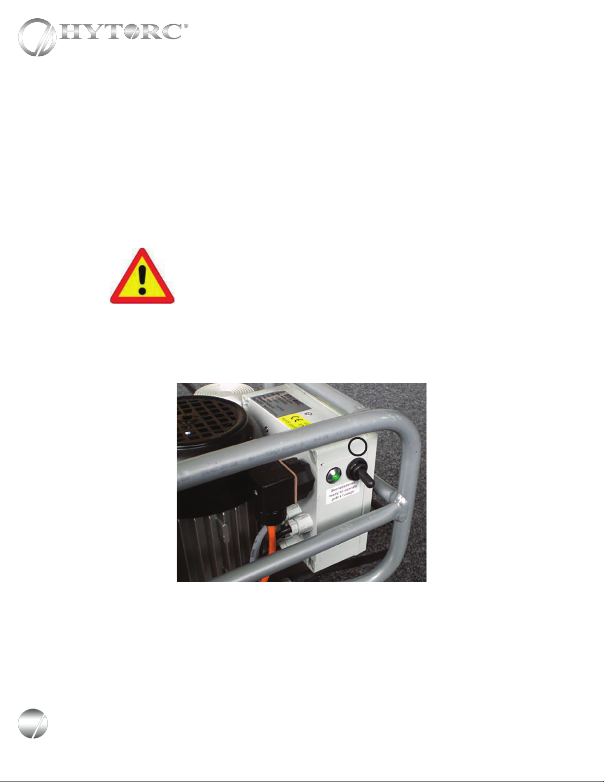
a safe distance. Ensure fasteners are in good shape. Check out tool functioning with drive or hex
ratchet turning in one direction only and check out gauge from a safe distance that needle is on zero
at no pressure and at 10,000 psi at high pressure. Keep high pressure on and check system visually
for leaks. Please keep in mind that hydraulic tools are very strong and work at high pressure.
HANDS-FREE WASHER APPLICATION: Make sure the drive and the tool are locked on securely.
FREE ANNUAL TOOL INSPECTION: With the purchase of HYTORC, you have the right to a FREE
annual tool inspection, which includes free seals, springs, connectors, and free lubrication. In case
of damaged or worn parts, the rst inspection within 12 months of purchase is free of charge.
Thereafter, you will be informed of any cost prior to replacement. Any part replaced and charged by
us will be sent to you for your inspection upon request when P.O. is issued.
FREE LOANER TOOLS: In case of tool failure during the warranty or rental period, please contact
your local HYTORC Agent for a free loaner tool 24/7.
HOSE REPLACEMENT: Hose replacement is recommend every three years, however we recommend
yearly hose inspections.
PLEASE WEAR REQUIRED SAFETY ATTIRE and use common sense during operation.
HELP: If you require any further assistance, please call your local HYTORC Representative or
1-800-FOR-HYTORC (1-800-367-4986), on the web at www.hytorc.com 24/7! It’s live!
PLEASE REVIEW THESE SAFETY
TIPS BEFORE EVERY TOOL USE
No. Safety 1-2-1009
HANDS-FREE BOLTING: The tool you have purchased may be capable of hands-free operation
when used with a HYTORC Washer™. We recommend the use of this washer to increase safety and
accuracy and reduce job time. If your bolting system is not compatible with the HYTORC Washer™,
the tool should be used with a limited movement reaction xture and a safety handle to reduce the
risk of nger pinching during operation. For more information, please contact us at 1-800-367-4986
or www.hytorc.com.
HYDRAULIC OIL REPLACEMENT: We recommend that the oil be changed every three months.

CONTENTS
HYDRAULIC PUMP
OPERATIONAL MANUAL
INTRODUCING HYTORC 5
SECTION I
GENERAL OPERATING INSTRUCTIONS 6
SECTION II
PUMP AND OPERATIONAL CONTROL 7
SECTION III
CONNECTING THE HYDRAULIC WRENCH 8
SECTION IV
FUNCTIONAL CHECK 9
SECTION V
REMOTE CONTROL 10
SECTION VI
SETTING PRESSURE AND TORQUE 11
SECTION VII
LED LIGHTS FOR SYSTEM MONITORING 13
SECTION VIII
ATEX EXPLOSION PROTECTION 14
SECTION IX
PREVENTATIVE MAINTENANCE 18
SECTION X
TROUBLESHOOTING 19
APPENDICES 23
A User Manual FA1
B User Manual FA4
C Declaration of Conformity
D ATEX Explosion Proof Certificate
E Material Safety Data Sheet
F Material Safety Data Sheet Canada
5
Leading Innovation in Industrial Bolting Since 1968
The World’s Most Trusted Industrial Bolting Systems

THANK YOU FOR BUYING HYTORC!
YOU ARE NOW HOLDING ONE OF THE WORLD'S LARGEST SELLING AND
MOST ADVANCED INDUSTRIAL BOLTING SYSTEMS.
HYTORC is used more often, by more industries on more applications than all others combined.
If you maintain your new pump properly, it will last for years to come.
This manual is designed to provide you with the basic knowledge required to operate and maintain your HYTORC
pump. Please read this manual carefully and follow the instructions provided. If you have any questions regarding
your HYTORC tool, please call us directly at 201-512-9500 or fax 201-512-0530.
Finally, your purchase of this HYTORC tool entitles you to the following FREE services:
• Free on-site training in the application and operation of your HYTORC equipment
• Free semi-annual training
• Free annual inspection
• Free loaner in case of pump failure
• Free engineering assistance by calling 1 800 FOR-HYTORC, or our continental office
Your local HYTORC ofce was informed of the delivery of this equipment. Should you require immediate training,
please feel free to call us directly to arrange an appointment with you at your convenience.
An instructional CD is also available for basic training and occasional brush up on operating procedures.
For additional information please visit our website at www.hytorc.com
Again, thank you and welcome to HYTORC!
Worldwide Warranty
HYTORC equipment is engineered to the latest technological standards and is backed by our exclusive
12-word, 12-month warranty.
"YOU BREAK IT UNDER NORMAL USE, WE FIX IT FREE OF CHARGE!"
If a HYTORC Pump cannot be repaired on-site, FREE loaner HYTORC equipment will be made available to you
upon request.
UNEX CORPORATION OR ITS DEALERS SHALL NOT BE LIABLE FOR LOSS OF PRODUCT OR OTHER INCIDENTAL OR CONSEQUENTIAL COSTS INCURRED BY THE BUYER OR THE USER.
HYTORC Offices Worldwide
Europe HYTORC Europe Tel. 33-1-4288-6745
Japan HYTORC Japan Tel. 81-3-3314-3315
Australia HYTORC Australia Tel. 61-8-8293-8411
United Kingdom HYTORC UK Tel. 44-16-7036-3800
Brazil HYTORC South America Tel. 55-21-2223-2944
All Others HYTORC USA Tel. 201-512-9500 /800-FOR-HYTORC
6Leading Innovation in Industrial Bolting Since 1968
The World’s Most Trusted Industrial Bolting Systems

SECTION I
GENERAL OPERATING
INSTRUCTIONS
All HYTORC Power Packs operate in a pressure range from 500 to 10,000 PSI, and are fully adjustable. They have
been engineered and designed for portability and high ow for increased speed. Before using your HYTORC power
pack, check the following points:
• Is the reservoir filled with oil?
• Where is the closest electrical outlet at the job site?
• Is there enough air pressure (100 PSI) and flow at the job site? (Pnuematic only)
• Is the gauge mounted and rated for 10,000 PSI?
• Is the oil filler plug securely in place?
IMPORTANT SAFETY INSTRUCTIONS
This pump is engineered to the latest technological and safety standards. In order to maintain these condi-
tions, and to ensure proper operation, the user must follow the instructions for use and safety precautions.
Please read this operating manual carefully and follow the instructions provided.The pumps are delivered
without oil in the tank. Before starting the hydraulic pump, fill the pump with hydraulic oil.
Look at oil fill level on the oil sight gauge. The oil level is correct when
the top gauge is half full. Please note that the oil level should not be
above the red mark of the top oil sight The technical information in this
manual has been collected with utmost care. However, there is always
a possibility of minor errors or typos. Therefore, HYTORC cannot be
held legally accountable for incorrect information provided. Please
contact us if you have any questions or if you believe there may be an
error in the manual.
Technical improvements for our products are subject to change without
prior notice.
This manual is designed to provide you with the basic
knowledge required to operate your hydraulic pump.
Please read this manual carefully and follow the
instructions provided.
7
Leading Innovation in Industrial Bolting Since 1968
The World’s Most Trusted Industrial Bolting Systems

SECTION II
PUMP AND OPERATIONAL
CONTROLS
OPERATIONAL CONTROLS (DEPENDING ON PUMP MODEL):
1. Hydraulic couplers (4-tool adapter on pump in picture)
2. Plug for main power cord
3. Remote control
4. Pressure regulator
5. Analog gauge
6. Plug for oil filler
1
2
3
4
5
6
8Leading Innovation in Industrial Bolting Since 1968
The World’s Most Trusted Industrial Bolting Systems

SECTION III
CONNECTING THE HYDRAULIC
WRENCH
When using hydraulic hoses for a tool and pump, make sure the hoses are rated for pressure of 40,610 PSI/2800. The
system is equipped with safety couplers which prevents the hoses from loosening accidentally.
Connect the twin-line hose as shown below. To connect the twin-line hose, make sure male couplers are connected to
female couplers. Hold the hoses as shown in the picture below labeled (A). Ensure the connectors are fully engaged and
tightened to the nal thread (B). Loose or improperly threaded couplers will prevent the tool from operating and can be
potentially dangerous if pressurized.
DO NOT USE PLIERS to tighten the couplers. Severe over-tightening can cause thread failure. Knurled sleeve on
couplers need to be hand tight only. (Please also see “Releasing the pressure”)
To loosen the couplers, turn it counter clock-wise. It is normal for a small amount of oil to drip from the couplers
when disconnected.
RELEASING THE PRESSURE
Before loosening the couplers, release the pressure in the system (There might be residual pressure). Hold the STOP
button and push the ON button on the remote control to release the pressure from the system.
9
Leading Innovation in Industrial Bolting Since 1968
The World’s Most Trusted Industrial Bolting Systems

SECTION IV
FUNCTIONAL CHECK
All HYTORC pumps are supplied completely assembled and are ready to use. A HYTORC Hydraulic Power Pack,
for use with your HYTORC tools, is recommended to provide the safety, speed, pressure and portability that make the
tools more efcient and accurate.
Before using the system, it has to be checked for its function and to make sure that no oil leaks occur. Set the pump to
max. pressure of 700 bar (10,000psi) and advance and retract the tool a few times.
Before you start the pump, turn the lock nut of the pressure regulator counter- clockwise, plug the power cord into
an outlet, and use the toggle switch *(A) to turn the pump on.
Do not hold the tool in your hands while performing the
functional check!
Do not touch moving parts!
*Some models may not have a toggle switch. To start a pump without the toggle-switch, plug the power cord into an
outlet and start the pump by pushing the manual button on the remote control.
A
10 Leading Innovation in Industrial Bolting Since 1968
The World’s Most Trusted Industrial Bolting Systems

SECTION V
REMOTE CONTROL
The pumps can be equipped with different remote control models. However, the mode of operation for any remote
control is:
• PUSH (A)-PUMP IS ON / TOOL ADVANCES
• RELEASE (A)-PUMP IS ON / TOOL RETRACTS
• PUSH (B)-PUMP IS OFF
• PUSH AND HOLD (C)-TOOL ADVANCES AND RETRACTS AUTOMATICALLY UNTIL (C) IS RELEASED
• TOGGLE SWITCH (D)-FORWARD (ON) DOWNWARD (OFF) (PNUEMATIC PUMPS)
MANUAL PUMP AUTOMATIC PUMP
A
AA
A
A
A
B
C
C
C
C
A
A
B
BB
D D
B
B
11
Leading Innovation in Industrial Bolting Since 1968
The World’s Most Trusted Industrial Bolting Systems

SECTION VI
SETTING THE PRESSURE / TORQUE
On manual bolting applications, the torque value has to be set with the pump pressure. Therefore, every calibrated
tool comes with a certicate. We recommend using tools that have been calibrated to increase safety and accuracy.
It is also recommended to have all tools re-calibrated once a year. To make sure that the certicate matches with a
certain tool, compare the tool model and serial number of the tool. Both, the tool model and the serial number are
engraved in the housing of the tool.
Turn the lock nut on the pressure regulator counter-clockwise. To start the pump: push the green button (A) and hold
it. To adjust the pressure, turn the pressure regulator (B) clockwise. The actual pressure is visible on the gauge at
any time.
To determine the correct torque value, refer to the torque chart on the back of the calibration certicate. The detailed
torque chart shows pressure values in steps of 20bar. After adjusting the pressure, hand tighten the lock nut on the
pressure regulator by turning it clockwise.
AVANTI-1
E1939
AVANTI-1
AVANTI-1
E1939
AVANTI-1
AVANTI-1 E1939
AVANTI-1
Calibration Certificate with Serial Number (Draft)
Pressure-Torque Chart (Draft) in a Calibration Certificate (100 bar steps)
Tool With Serial Number (Draft)
DRAFT
12 Leading Innovation in Industrial Bolting Since 1968
The World’s Most Trusted Industrial Bolting Systems

Applying the Torque Wrench - the Tightening Process
1. Having set your target pressure, cycle the tool three or four times to full pressure before putting it on the
application. Cycling the tool ensures that the system is operating properly and removes trapped air, if any.
2. Place the proper size impact socket on the square drive and secure properly with a locking ring and pin.
3. Place the tool and the socket on the nut, making sure that the socket has fully engaged the nut. Further ensure
that the drive retainer is engaged.
4. Make sure the reaction arm is rmly abutted against a stationary object (e.g. An adjacent nut, ange, equipment
housing etc.)
5. When positioning the wrench, make sure that the hose connections are well clear of any obstructions, and that
all body parts are safely out of harm’s way.
6. THEN, AND ONLY THEN, apply momentary pressure to the system to ensure proper tool placement. If it
doesn’t look or act right, stop and re-adjust the reaction arm.
Setting the Pressure/Torque Continued
Turn the lock nut on the pressure regulator counter-
clockwise. To start the pump: push the green button
(A) and hold it.
To adjust the pressure, turn the pressure regulator
(B) clockwise. The actual pressure is visible on the
gauge at any time.
To determine the correct torque value, refer to
the torque chart on the back of the calibration
certicate. The detailed torque chart shows pressure
values in steps of 20bar.
After adjusting the pressure, hand tighten the
lock nut on the pressure regulator by turning it
clockwise.
13
Leading Innovation in Industrial Bolting Since 1968
The World’s Most Trusted Industrial Bolting Systems

SECTION VII
LED LIGHTS FOR SYSTEM
MONITORING
The HY-115 Pump is now equipped with
(3) three-colored LEDs integrated into the electric
control box for system monitoring.
Upper LED: Low voltage
• green when voltage above 95V = o.k.
• yellow when voltage between 95V and 80V
• red when voltage below 80V
• motor switches off when below 77V for more
than 5 seconds
Middle LED: High voltage
While not running
• generally green when voltage below 138V
• when above 138V all LEDs will ash red
While running
• green when voltage below 128V
• all three LEDs blink red when voltage above or equal to 128V, motor switches off after 5 seconds
Lower LED: Temperature
Oil temperature
• green when temperature between +32°F (0°C) and +194°F (90°C) = o.k.
• yellow when temperature below +32°F (0°C) (solenoid valve locked) or above +194°F (90°C)
• red when oil temperature above +212°F (100°C) (motor switches off)
Motor temperature
• green when coil temperature below +356°F (180°C) = o.k.
• red when coil temperature above +356°F (180°C) (motor switches off)
14 Leading Innovation in Industrial Bolting Since 1968
The World’s Most Trusted Industrial Bolting Systems

Definition: HYTORC hydraulic bolting system, suitable for hazardous areas:
The bolting system, which can be used in hazardous areas, consists of at least three components:
1. Modied pneumatic HYTORC Pump HY-AIR
2. Modied twin hose, nominal diameter 6 mm
3. Modied HYTORC Low Clearance Wrench STEALTH and / or HYTORC Square Drive Wrench AVANTI
and / or ICE.
1. Modied component: HYTORC HY-AIR Pneumatic pump must be equipped as follows:
a) Solid metal spring on each male and female coupling (between coupler and tting).
ATTENTION: Only modified HYTORC hydraulic torque wrenches STEALTH, AVANTI and ICE,
modified twin hoses (only nominal diameter 6 mm) as well as the modified pneumatic
HYTORC Pump JetAir-12 shall be used in hazardous areas!
SECTION VIII
IMPORTANT INSTRUCTIONS FOR ATEX
CERTIFIED PNEUMATIC PUMPS FOR
EXPLOSION PROTECTION
The device can be used in hazardous areas as follows:
Explosion-proof hydraulic torque controlled bolting system
HYTORC Division of UNEX Corp.
333 Route 17 North
Mahwah, New Jersey 07430 U.S.A.
EPS 13 ATEX 2 561 X
EX II 2 G EX c IIB T4
CE
15
Leading Innovation in Industrial Bolting Since 1968
The World’s Most Trusted Industrial Bolting Systems

2. Component: The HYTORC hydraulic twin hose, with a nominal size of 6 mm (color mint-yellow).
ATTENTION: HYTORC hydraulic twin hoses with a
diameter smaller than 6mm are not suited for
explosion protection.
The twin hose nominal size 6 mm must be
equipped as follows:
a) Solid metal spring on each male and female coupling (between
coupler and tting). Each twin hose has two pairs of couplers,
and therefore four couplers
b) Equipped with a plastic remote control FBP-A5 art.-No.: 31044774
or FBP-A10 art.-No.: 33150200. Only this plastic remote control
has passed the electric charge and capacity test.
Qualied Personnel:
The bolting system may be operated only by trained and experienced personnel for explosion protection.
Conductivity:
Conductivity of the entire system is ensured by several solid metal springs,
- HYTORC Pneumatic Pump JetAIR 12.A connected securely to the hydraulic hose
- HYTORC Hydraulic Twin Hose (diameter 6 mm) connected securely to the tool
Explosion protection is guaranteed if:
The explosion protection is only guaranteed when all springs (pneumatic pump, twin hose
and tool) are attached tightly. When in doubt about the conductivity of the connection, attach
a standard multi-meter between the tool and the end of the ground wire and take a resistivity
measurement.
Ground wire:
Avoid electric-potential differences between plant and tool. Before initial
operation in explosive areas, a ground wire has to be attached between
the HYTORC Pneumatic Pump (No Electric Pump to be used!) and the plant.
The ground wire must be supplied by the operating company.
16 Leading Innovation in Industrial Bolting Since 1968
The World’s Most Trusted Industrial Bolting Systems

Final recommendation for explosion protection:
3. Component: The HYTORC hydraulic torque wrench. The torque wrench must be equipped as follows:
a) Solid metal spring on each male and female coupling (between coupler and tting).
b) The joints of the swivel on the hydraulic wrench must not be ANODIZED!
Only the polished swivel can be used!
To ensure an effective explosion protection,
it is imperative to comply with the instructions
mentioned above. It is recommended to have the
explosion proof system inspected by a
HYTORC Specialist on a regular basis.
This system should include anti-sparking
sockets and a grounded ange.
17
Leading Innovation in Industrial Bolting Since 1968
The World’s Most Trusted Industrial Bolting Systems

Important note:
Other anodized HYTORC swivels, for example MXT swivels, are NOT suited for explosion protection!
Example: Pink anodized STEALTH swivel Example: Blue anodized MXT swivel
Not suited for explosion protection! Not suited for explosion protection!
The HYTORC HY-AIR hydraulic pump is equipped as follows:
18 Leading Innovation in Industrial Bolting Since 1968
The World’s Most Trusted Industrial Bolting Systems

SECTION IX
PREVENTIVE
MAINTENANCE
Preventive Maintenance -
Hydraulic Power Packs
HYTORC Hydraulic Power Packs are precision-built units and, as such, do require a certain amount of care and
maintenance.
• Hydraulic Oil
Oil should be completely changed after every 40 hours of operation, or at least twice a year. Always make sure the
reservoir is lled with uid. If additional oil is required, use only high-grade hydraulic oil.
• Quick-Disconnects
Fittings should be checked periodically for leaks. Dirt or foreign materiais should be kept away from ttings.
Clean before use.
• Hydraulic Gauge
Some gauges are liquid lled. Should this liquid level drop, it indicates external leakage, and replacement is
necessary. Should the gauge ll with hydraulic oil, it indicates internal failure and it should be discarded.
• Filter on Pump
The lter should be replaced twice a year in normal use and more often if the pump is used daily or in a dirty, harsh
environment.
• Remote Control
(Air Unit) The air line to the remote control unit should be checked for obstructions or kinks in the line periodically.
If there is a bend or break in the line, it must be replaced. The spring-loaded buttons on the remote handle should be
checked in the event of operating difculties. (Electric Unit) The rocker switch should be checked periodically if
any indication of problems exist.
• Air Valve
This valve should be checked twice a year.
• Brushes and Brush Holders
(Electric Unit) Check and replace, if worn.
• Armature
(Electric Unit) Check yearly.
19
Leading Innovation in Industrial Bolting Since 1968
The World’s Most Trusted Industrial Bolting Systems

SECTION X
TROUBLESHOOTING
SYMPTOM PROBABLE CAUSE REQUIRED ACTION
Gauge shows pressure build-up but the
tool will not cycle
1. Couplings loose or inoperative
2. Solenoid inoperative
1. Tighten and/or replace couplings. Use Test #1
listed below to isolate problem.
2. Check using test #2 below. If solenoid is bad,
replace.
Cylinder will not retract. 1. See above
2. Voltage to electric pump is too low
to line drop or inadequate amperage is
available.
3. Linkage between piston rod and drive
arms are broken.
1. See Above
2. Get shorter extension cord or upgrade to
12AWG, 25 amp rating or better. If shop power is
adequate, draw power from welding machine or cal
rod transformer.
3. Replace parts as necessary.
Cylinder pressure will not build. 1. Oil blow by in tool (Piston seal leak,
blown O-ring, cracked piston)
2. Pump Problem
1. Replace defective parts. SHOP JOB
2. Check to see if sub-plate is worn by; a) Remove
screws from pump motor to reservoir, slide Pump
motor to the side, turn pump on and while holding
down on the button, put your nger on the dump
tube (round tube under the directional control
valve) - if you feel pressure, then replace the sub-
plate and shear seals.
2A. Check to see if you have leaks from the
external relief valve and the 2 oil line connections
(bottom of relief valve and connection into pump
body’s other end) of oil line. If leaking, retighten
with 9/16” open end wrench. SHOP JOB
2B. If pump sounds like a lot of pebbles in a tin
can, the problem may be a worn motor coupling
Remove motor from base plate - using a pair of
needle nose pliers remove the motor coupling - if
worn, replace. SHOP JOB
2C. AIR PUMPS - Faulty Air Valve due to exces-
sive moisture and/or dirt in air supply. Disassemble
air valve and wipe any residue from air valve
piston - spray brake cleaner into air valve body,
dry thoroughly. Disassemble all small air lines and
blow out with compressed air. Lubricate both air
valve piston and body with hydraulic oil (sparingly)
and reassemble. SHOP JOB
2D. Air pumps - Faulty remote control valve
cartridge. Replace.
20 Leading Innovation in Industrial Bolting Since 1968
The World’s Most Trusted Industrial Bolting Systems
This manual suits for next models
6
Table of contents
Other Hytorc Water Pump manuals
Popular Water Pump manuals by other brands

Grundfos
Grundfos FireSAFE Series Installation and operating instructions

VEVOR
VEVOR GYB-630B user manual

APS
APS 55K DIESEL HUSKY Operation and maintenance manual

Xylem
Xylem Bell & Gossett 1335 Series Installation, operation and maintenance manual

Calpeda
Calpeda NCE GF Series Original operating instructions

Wayne
Wayne 330600-001 Operating instructions and parts manual

Calpeda
Calpeda GEO operating instructions

Homa
Homa TP 50 Original instruction manual

Homa
Homa C250 W Original instruction manual

Armstrong
Armstrong LIFT NT25 installation instructions

Gardner Denver
Gardner Denver Welch WOB-L 2511C-02 Operation manual

EBARA
EBARA EVM Series Operating and maintenance manual