I-CAN SEH400RB User manual

Brushless Motor Driver SEH400RB
Catalogue
1 Brief Instruction ...........................................................................................................................................2
1.1 Features ................................................................................................................................................2
2.1 Electrical Performance .........................................................................................................................2
4 Driver port and function description ...............................................................................................................3
4.1 Driver port ............................................................................................................................................3
4.2 Terminal Description ........................................................................................................................... 4
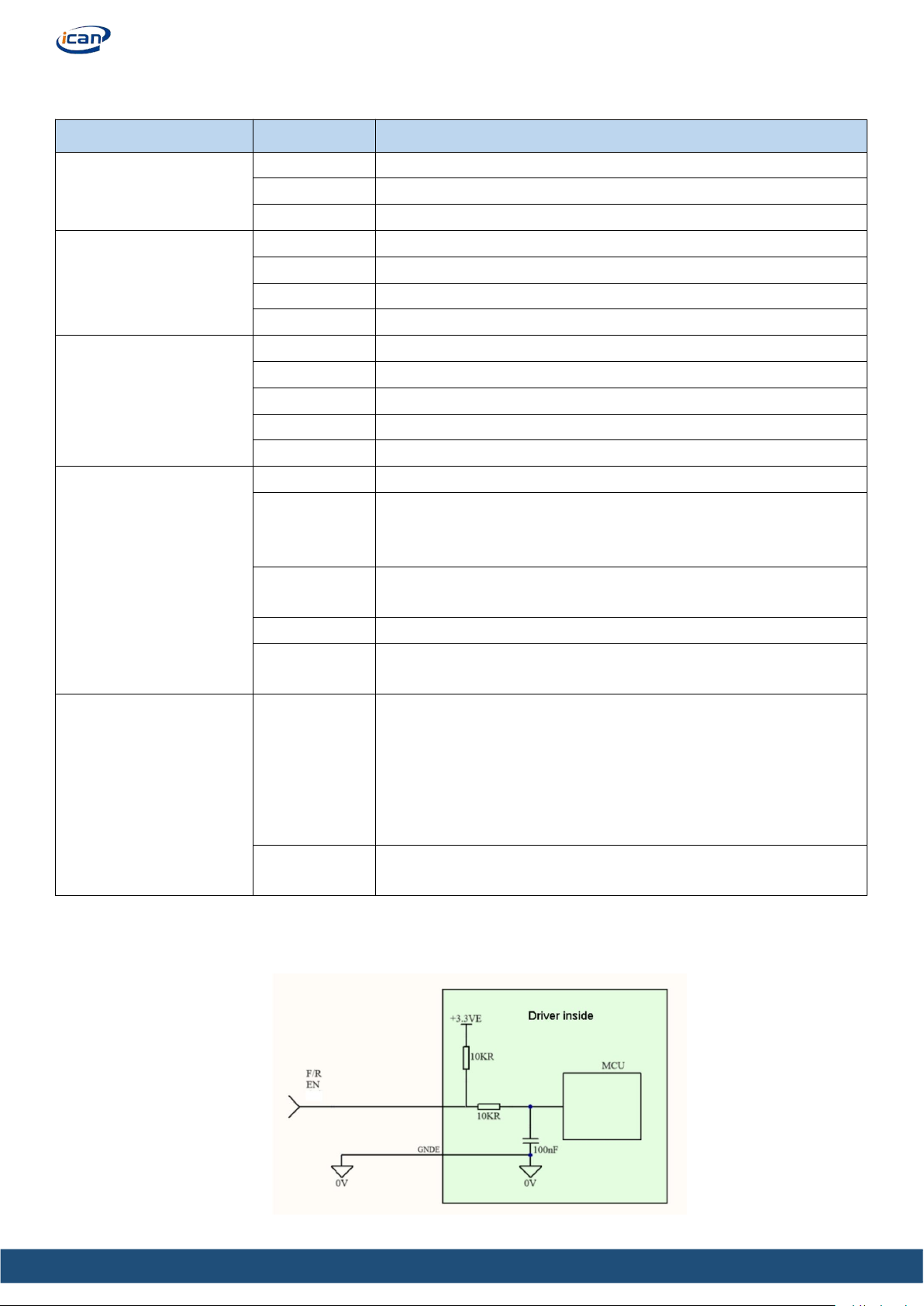
4.3 Description of external control signal circuit ...................................................................................... 4
4.4 Output circuit description .................................................................................................................... 5
5 Introduction to panel functions ....................................................................................................................... 6
5.1Panel functions ......................................................................................................................................6
5.2 Panel introduction ................................................................................................................................ 7
6.1 Start and stop ....................................................................................................................................... 9
6.2 Direction control. ................................................................................................................................. 9
6.3 Speed regulation mode. ........................................................................................................................9
6.4 RS485 .................................................................................................................................................11
7.2ALARM RESET .................................................................................................................................15
8 Troubleshooting ............................................................................................................................................ 15
After Sales Service ...........................................................................................................................................16

Brushless Motor Driver SEH400RB
BLDC MOTOR DRIVER
SEH400RB
1 Brief Instruction
The SEH400R BLDC Driver is suitable for high voltage three-phase BLDC Motor with a power of 400W
and below. This product has display, easy to operate, supports RS-485 communication protocol, can
provide built-in potentiometer speed regulation, external potentiometer speed regulation, analog voltage
speed regulation.
1.1 Features
Self-contained digital tube display, intelligent display of various parameters
Adjustable speed with knob
External potentiometer speed regulation
Acceleration and deceleration time setting
Pole pair setting
Alarm display
RS485
Rated speed accuracy as low as ±0.5%
2 Electrical performance and environmental indicators
2.1 Electrical Performance
Parameters
Min
Rated
Max
Unit
Voltage Input
120
220
250
VAC
Current Input
-
3.6
-
A
Current Input
-
-
6
A
Power output
-
400
400
W
Motor Speed
-
3000
Adjustable
rpm
The parameters of this table are suitable for normal temperature 25 ℃
2.2 Environmental Indicators
Environmental Factor
Environmental indicators
Cooling mode
Air cooling
Use occasion
Avoid dust, oil stain and corrosive gas
Operating temperature
-10℃~+60℃

Brushless Motor Driver SEH400RB
4.2 Terminal Description
4.3 Description of external control signal circuit
The F/R and EN terminals are as below,amplitude ranges less than 0.5V, or higher than 2.5VDC
Signal
Terminals
Description
Power input
L
Power+
N
Power-
E
Ground
Motor lines
U
Motor U
V
Motor V
W
Motor W
E
Ground
Motor hall lines
+5VE
Hall sensor +
HA
Motor hall sensor Hu
HB
Motor hall sensor Hv
HC
Motor hall sensor Hw
GNDE
Hall sensor -
Control signals
SV
External potentiometer speed regulation
EN
If EN and GNDE connect, the motor runs;
If EN and GNDE disconnect, the motor stops. (They disconnect
by default.)
F/R
If F/ and GNDE connect, the motor runs anti-clockwise
If F/ and GNDE disconnect, the motor runs clockwise
GNDE
Control signal common ground port
BRK
Under port control mode P-03-4, BRK connects with GNDE, the
motor brake stops
Output signals
SPD
Frequency output.
The relationship between the frequency detected and the speed is:
N(rpm)= F
F: Output pulse frequency(Hz)N: Motor speed
For example:F=500Hz, then N(rpm)=500
(Note: Motor poles should be set right)
ALM
It is a high resistance output, and when a fault occurs, it outputs a
low level

Brushless Motor Driver SEH400RB
5 Introduction to panel functions
5.1Panel functions
Functions
Description
Operation
mode
Display
Speed display
Display
Temperature display
Drive cooling temperature display
Speed regulation mode
selection
0. Internal knob speed regulation
Parameter
setting
1. External analog speed regulation
2. Key speed regulation or 485 speed regulation
Speed setting
Step size is 100RPM; The set speed is lower than (400rpm/ pole
pairs) and the motor does not rotate;
Direction setting
0. Motor stops;
1.Enter the relevant menu through the panel key to set the forward
rotation;
2.Enter the relevant menu through the panel keys, and set the reversal
3.Motor brakes;
4.Direction port control.(F/R, EN)
Reduction ratio setting
Set the speed ratio of the reducer;
Alarm reset
Display the alarm code and press SET to reset the alarm
Polar number setting
Set the pole pairs of the adaptive motor (It is not recommended to
change the pole pairs during motor operation);
Under speed time setting
Set the under speed time. (E.g, set it as 5s, when the speed of the
motor is less than 50% of the set speed for over 5s, the motor will
stall.)
Maximum speed setting
Set the upper limit of the speed (it is recommended to set it to the
maximum speed of the motor);
Acceleration and
deceleration time setting
Set the ACC and DEC time through the panel keys;
485 communication
address control
Select and control 485 communication address in steps of 1;
485 communication rate
setting
Set the 485 communication rate in steps of 1;
Port indication
Indicates the status of each IO port, read-only;
Data initialization
Restore the operation data to the factory setting;

Brushless Motor Driver SEH400RB
6.Function setting of external control port.
6.1 Start and stop
EN and GNDE are disconnect by default, When the power is turned on, the
motor will not rotate. There are two ways to start the motor:
1. Press START to start and STOP to stop the motor.
2. Connect EN and GNDE. A switch or PLC can be added between EN and
GNDE to control the motor start and stop. See right.
6.2 Direction control.
Here are two methods to control the direction.
1. Through the panel MODE->P-03.
2. Disconnect F/R and GNDE, motor runs clockwise.
Connect F/R and GNDE, motor runs anti-clockwise.
6.3 Speed regulation mode.
6.3.1. Knob speed regulation.(Default method.)
6.3.2 MODE->P-01->SET->2 to select speed regulation with keys, press page up or page down to select
request speed.
6.3.3 In addition to using the built-in potentiometer knob on the panel for speed regulation, the external
port SV can be used for the following settings for speed regulation. To start, set MODE->P-01->SET->1.

Brushless Motor Driver SEH400RB
1. External potentiometer speed regulation.
10KΩ is recommended to adjust the speed.
Connect the central pin of the external potentiometer to
the SV terminal, and connect the other two pins to the
GNDE port and the +5VE port respectively.
(Refer to the picture below for details)
2. External analog signal role DC 0-5V
Note: Be sure to set the correct number of motor pole pairs.
(Relationship between speed command voltage and motor speed)
The above is the measured diagram of a 3000rpm motor. When the input voltage is 0.3V, the motor speed is
183rpm. When the input voltage is about 5V, the motor speed is 3000rpm.

Brushless Motor Driver SEH400RB
6.4 RS485
The communication function of this driver adopts Modbus protocol, which conforms to the standard GB/T
19582.1-2008. Using RS485-based two-wire serial link communication, the physical interface adopts
3.81mm, 3PIN plug-in terminal, the terminal definition is shown in the figure below, and three wires need to
be connected: B, A, GNDE. The communication address can be set through the panel operation. The 120Ω
terminal matching resistance needs to be externally connected by the user.
Communication conditions
Interface
3.81mm、3PIN Plug-in terminal block
Bus
RS485
Protocol
MODBUS
Communication
mode
Half duplex
Standard
GB/T 19582.1—2008
Communication
rate
9600(can be set)
Data bit
8 bit
Stop bit
1 bit
Check
ModbusCRC low order first
Communication
node
247

Brushless Motor Driver SEH400RB
Refer to the following table for the address of read / write register:
READ
Slave
address
(1byte)
Function
code
(1byte)
Access
address
1*
(2byte)
Access
address
2*
(2byte)
Access
data
(2byte)
CRC
Check
(2byte)
Read parameters
Value
Range
Defaul
t value
Unit
0Xnn
0X03
(Read data)
0X0000
0X0054
0X0001
CRC
Check
Speed mode selection
0-2
0
0X0001
0X0056
Speed setting
0-Max speed
0
RPM
0X0002
0X005F
Speed Value
0-65535
0
RPM
0X0003
0X0066
Motor direction
0-4
1
-
0X0004
0X0068
Gear ratio
1-100
1
-
0X0005
0X0076
Alarm code
0
-
0X0006
0X0086
Pole pairs number
1-100
4
0X0007
0X0090
Under speed time read
0-100
2
s
0X0008
0X0092
Max speed
100-65535
3000
RPM
0X0009
0X0098
ACC/DEC time
0-150
5
0.1s
0X000A
0X00D2
Temperature
-300-1250
-
0.1℃
0X000B
0X0113
Program version
-
-
-
0X000C
0X0129
Port indication
-
-
-
0X000D
0X012A
Port indication
-
-
-
*: Access address 1 and access address 2, you can choose one of the two, access address 1 is easy to read, and access address 2 is
recommended to use 0X0001 to access data.

Brushless Motor Driver SEH400RB
The write register address can refer to the following table:
WRITE
Slave
address
(1byte)
Function
code
(1byte)
Access
address
(2byte)
Access
data
(2byte)
CRC
Check
(2byte)
Write parameters
Value
Range
Default
value
Unit
0Xnn
0X06
(Write data)
0X0054
0X0000
CRC Check
Speed adjusting mode
0-2
0
-
0X0056
0X0000
Speed setting
0-Max
speed
0
RPM
0X0066
0X0001
Motor direction setting
0-4
1
-
0X0068
0X0001
Gear ratio setting
1-100
1
-
0X0076
0X0001
Alarm Reset
-
-
-
0X0086
0X0004
Pole pairs setting
1-100
4
-
0X0090
0X0002
Under speed time
0-100
2
s
0X0092
0X0BB8
Max speed
100-65535
300
RPM
0X0098
0X0005
ACC/DEC time setting
0-150
5
0.1s
0X00BC
0X0001
Parameter saving
-
-
-
0X00CC
0X0001
Factory setting recovery
1
Parameter description refer to the table below:
Parameters
Description or note
Speed adjusting modes selection
0:Knob speed regulation;1:External analog quantity;2:key or communication;
Speed setting
The motor does not rotate when the set speed is lower than (400RPM/pole pair number)
Speed feedback
If the reduction ratio is set, the final speed is speed / reduction ratio
Direction setting
0:Stop;1:Clockwise;2: anti-clockwise;3:Brake;4:Port control(F/R, EN)
Gear ratio setting
Note: Speed = motor speed / gear ration;
Alarm code
Read: read alarm code; write 0x0001: alarm reset;
Poles pairs number
It is not recommended to change the number of pole pairs during motor operation;
Under speed time
0 is for no under speed protection;
Max speed
It is recommended to set the maximum speed to the rated speed of the motor;
ACC/DEC
ACC/DEC time
Temperature
Radiator temperature of the drive
Program version
Read: read program version; write 0x0001: parameter restore factory settings
Port indication
Indicate the status of each IO port (0X0129 is the upper 16 bits);

Brushless Motor Driver SEH400RB
7Alarm description and fault handling
7.1Alarm code description
When over voltage, or the signal of the Hall sensor is wrong, etc., the following situations will occur:
1. The ALM port of the driver is automatically connected to the GNDE port, the ALM port becomes low
level, and an alarm signal is sent to the upper computer (In this case, wiring operation is required to send a
signal to the upper computer).
2. The motor will stop naturally and the motor output shaft will turn freely.
After a fault alarm occurs, you can press MODE-> P-05 through the display panel and press the SET button
to to view the alarm code.
Alarm Code
Alarm name
Alarm Reasons
Troubleshooting
AL00
No error
-
-
AL02
Over temperature
1. There is a foreign object blocking the fan
or dust accumulation;
2. The motor does not match the driver;
3. The drive is damaged;
1. Clean the driver;
2. Re-match the motor and driver
selection;
3. Replace the driver;
AL05
Hall error
1. Check whether the motor sensor cable is
firmly connected
2. Check whether the Hall element in the
motor is damaged;
3. Internal communication error of the
drive;
Automatic recovery after the fault
is cleared;
AL08
Under speed
1. Check whether the set maximum speed
is not greater than the rated speed of the
motor;
2. Check whether the number of pole pairs
is set correctly;
3. Try to stop the motor or power on again
to reset the alarm;
The time when the feedback speed
is lower than the set speed exceeds
the set underspeed time, and the
default underspeed time is 2
seconds;
AL09
Module alarm
IPM Power Module Alarm
1. Detect whether there is dust
entering;
2. Try to lengthen the acceleration
and deceleration time;
3. Re-power;
4. If the alarm still occurs,
replace the driver
AL10 —
AL26
Hardware failure
Please check for iron filings, corrosion,
dust
Re-power on, if it still doesn't
work, replace the controller;
AL40 —
AL43
Storage error
Please check for iron filings, corrosion,
dust

Brushless Motor Driver SEH400RB
7.2ALARM RESET
If the above solutions don’t work, follow the operations below to reset the alarm signal
1. MODE->P-05->SET to check the alarm code, then press SET to reset the alarm.
2. Cut off the power supply, then power on again after 1 minute, the alarm can be released.
8 Troubleshooting
Phenomenon
Possible reason
Troubleshooting
Motor stop
Alarm
Do as alarm code
Press Stop
Press Start
Wrongly motor lines
Check the wiring and phase
Motor brake is wrong
Make sure the motor brake is open
Driver doesn’t match the motor
This driver only supports motors with a Hall electrical
angle of 120°
Damage
Replace new motor and driver
Over heat
Over load
Make the load lower
Over current
Make the current lower
The ambient temperature is too high
Improve environmental heat dissipation.
Wrong phase
Correct phase connection
Damage
Replace new motor and driver
Abnormal
motor speed
Overload
Make the load smaller
Signal input wrongly
Signal input checking
Wrong poles pairs numbers setting
Set the right poles numbers
Wrong gear ratio setting
Set the right gear ratio
Wrong max speed setting
Set the maximum speed to the rated speed of the actual
motor
The motor is
running with
abnormal
noise
Phase wrongly
Check the motor phase
Driver doesn’t match the motor
This driver only supports motors with a Hall electrical
angle of 120°
Lack of phase wiring
Check the motor phase
Load problem
No load operation motor test
Motor problem
Change the motor
Motor speed
fluctuations
Signal input wrongly
Change to knob speed setting to check if there is the
same error
The load inertia ratio is too large
Decrease load inertia ratio or increase gear box
The load is changeable
Steady load or this condition is normal
No signal
output
Pull-up resistor not connected
The alarm output interface and the speed output interface
are connected with appropriate pull-up resistors

Brushless Motor Driver SEH400RB
After Sales Service
Warranty:
The warranty is 12months from the date of shipment. We offer free technical support during the time.
Repair progress:
(1)Contact the sales to tell the details.
(2)Send back the product to:
Room 401, Building 2, No. 7, Xinhe Shengfeng Road, Wanjiang Street, Dongguan City, Guangdong Pr
ovince, China
Warranty Limitations
Damage caused by improper use of products is not covered by the warranty.
Product damage caused by the use environment or electric parameters that does not meet the use
parameters is not covered by the warranty.
Product damage caused by improper selection is not covered by the warranty.
Product damage caused by unauthorized processing, repair, transformation, or decomposition of this
product is not covered by the warranty.
Product damage caused by improper wiring, such as reverse polarity of the power supply and live
plugging and unplugging of the motor leads, is not covered by the warranty
Technical support
Consultation on the selection method and use method of motor and driver
Hotline: 400-696-4446
TEL:0769-22327568
Time:Monday-Friday
9:00~12:00、13:00~17:00
Data download
https://www.ican-motor.com
Table of contents
Other I-CAN Servo Drive manuals
Popular Servo Drive manuals by other brands

SSD Drives
SSD Drives 637 product manual

Toshiba
Toshiba Q9 Series Installation and operation manual

Allen-Bradley
Allen-Bradley Kinetix 5500 user manual

Sanyo Denki
Sanyo Denki PE Series Installation and operation manual

Xinje
Xinje DS2 series manual

Allen-Bradley
Allen-Bradley 2097-V31PR0 installation instructions

Eurotherm Drives
Eurotherm Drives 631 product manual

Kollmorgen
Kollmorgen AKD Fault Card

Leadshine
Leadshine 2ELD2-CAN Series user manual

Mitsubishi Electric
Mitsubishi Electric MR-J2S-60A4 Instructions and Cautions for Safe Use

Leadshine
Leadshine CS-D508 user manual

Allen-Bradley
Allen-Bradley 2099-BM06-S user manual