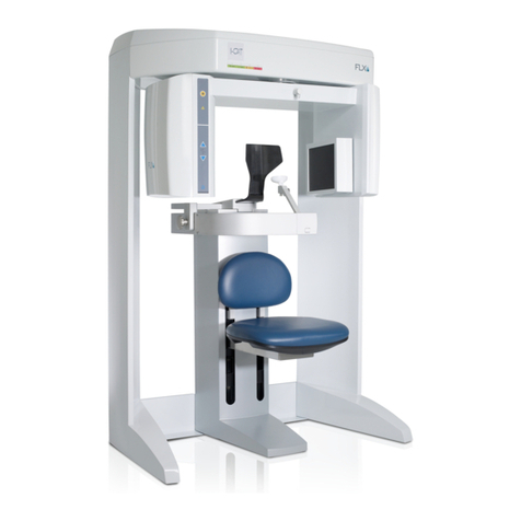
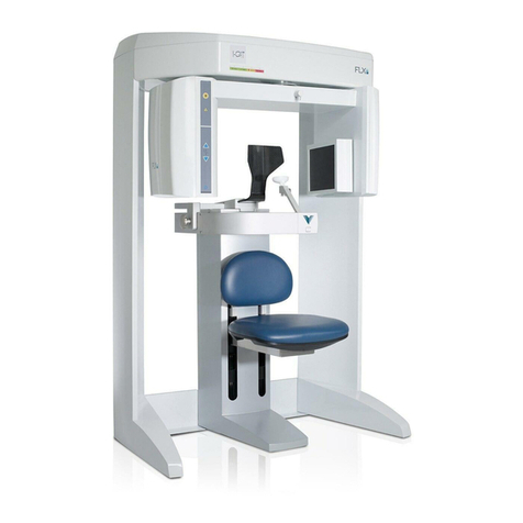
i-CAT FLX V Series Quick start guide

Technical Guide
Cone Beam 3D +
2D Panoramic Dental
Imaging System
TM
TM

Copyright © Dental Imaging Technologies Corporation 2013 - 2016
This manual contains original instructions by Dental Imaging Technologies Corporation for
the safe use of the i-CAT FLX imaging system and were originally drafted, approved and
supplied in English. Dental Imaging Technologies Corporation reserves the right to make
changes to both this manual and to the products it describes. Equipment specifications are
subject to change without notice. Nothing contained within this manual is intended as any
offer, warranty, promise or contractual condition, and must not be taken as such.
Thisdocumentmaynot,inwholeorinpart,becopied,photocopied,reproduced,translated,
or reduced to any electronic medium or machine-readable form without prior consent in
writing from Dental Imaging Technologies Corporation.
i-CATTM is a registered trademark of Imaging Sciences International. Other names may be
trademarks of their respective owners.
No part of this document may be reproduced or transmitted in any form or by any means,
electronic or mechanical, for any purpose, without prior written permission of Dental
Imaging Technologies Corporation. Names and data used in examples herein are fictitious
unless otherwise noted. The software program described in this document is provided to its
users pursuant to a license or nondisclosure agreement. Such software program may only
beused,copied, or reproducedpursuantto the termsofsuch agreement.Thismanual does
not contain or represent any commitment of any kind on the part of Dental Imaging
Technologies Corporation.

-iii
032-0328-EN Rev K
TABLE OF CONTENTS
Chapter 1 - Introduction
i-CAT FLX V-Series Imaging System Description .......................................................1-1
Operator Control Box ...................................................................................................... 1-2
Patient Emergency Stop Control ..................................................................................... 1-3
Software Description ...................................................................................................1-3
SmartScan STUDIO Software ......................................................................................... 1-3
TxSTUDIO Treatment Planning Software ....................................................................... 1-3
System Requirements .................................................................................................1-3
Chapter 2 - Startup and Shutdown
Scanner Startup ..........................................................................................................2-1
Power Up ......................................................................................................................... 2-1
Log in ............................................................................................................................... 2-1
Scanner Shutdown .....................................................................................................2-2
Log out ............................................................................................................................ 2-2
Power Off ........................................................................................................................ 2-2
Cycle Scanner Power ...................................................................................................... 2-2
Chapter 3 - Calibrations and Quality Assurance
Run Calibration and QA Tests ....................................................................................3-1
Panel Calibration .........................................................................................................3-2
Run Panel Calibration ..................................................................................................... 3-2
Panel Calibration Failure ................................................................................................. 3-2
Shutter Calibration ......................................................................................................3-3
Run Shutter Calibration ................................................................................................... 3-3
Shutter Calibration Failure ............................................................................................... 3-3
Geometric Calibration .................................................................................................3-4
Install Geometric Calibration Fixture ............................................................................... 3-4
Run Geometric Calibration .............................................................................................. 3-4

-iv
i-CAT FLX Technical Guide
032-0328-EN Rev K
QA Line Pair Test ....................................................................................................... 3-5
Setup QA Phantom ..........................................................................................................3-5
Run QA Line Pair Test .....................................................................................................3-6
QA Line Pair Evaluation ..................................................................................................3-7
Distance Measurement Test ............................................................................................3-9
QA Material Test ...................................................................................................... 3-10
Set Up QA Phantom ......................................................................................................3-10
Run QA Material Test ....................................................................................................3-10
QA Material Evaluation ..................................................................................................3-11
QA Air Water Test .................................................................................................... 3-14
Set Up QA Air Water Phantom ......................................................................................3-14
Run QA Air Water Test ..................................................................................................3-14
QA Air Water Test Evaluation ........................................................................................3-15
QA PAN Test ............................................................................................................ 3-20
Install PAN Phantom .....................................................................................................3-20
Run QA PAN Test .........................................................................................................3-20
QA PAN Test Evaluation ...............................................................................................3-21
Radiation Output Test .............................................................................................. 3-22
Measured Dose .............................................................................................................3-22
Interpretation .................................................................................................................3-23
Chapter 4 - Site Administration
Site Administrator Account ......................................................................................... 4-1
Configurator ................................................................................................................ 4-2
Accounts ..........................................................................................................................4-2
Institution .........................................................................................................................4-3
Network ...........................................................................................................................4-3
Maintenance ....................................................................................................................4-3
Dose LogBook .................................................................................................................4-4
Device Activity Log ..........................................................................................................4-4
Regular Backups of Image Data ................................................................................ 4-4

-v
Table of Contents
032-0328-EN Rev K
Chapter 5 - Data Utilities
Introduction .................................................................................................................5-1
Data Utility ..................................................................................................................5-1
Install and Configure Data Utility .....................................................................................5-2
Using the Data Utility .......................................................................................................5-3
Export Database to DEXIS Core .....................................................................................5-9
Patient Data Utility ......................................................................................................5-9
Install and Configure Patient Data Utility .......................................................................5-10
Using the Patient Data Utility .........................................................................................5-11
Appendix A - Safety Information
Important Safety Information ......................................................................................A-1
Electrical Hazards .......................................................................................................A-3
Explosion Hazard .......................................................................................................A-3
Mechanical Hazards ...................................................................................................A-3
Collision System ..............................................................................................................A-3
Tube Head Leakage ........................................................................................................A-4
Laser Beam Hazards ..................................................................................................A-4
Radiation Safety .........................................................................................................A-4
Radiation Protection Measures ........................................................................................A-5
Safety Devices ............................................................................................................A-5
Emergency Stops ............................................................................................................A-5
Warning System ..............................................................................................................A-5
Interlock System ..............................................................................................................A-6
Site Layout ..................................................................................................................A-6
Cabling Requirements ................................................................................................A-6
Appendix B - Product Information
Essential Performance ...............................................................................................B-1
User Proficiency .........................................................................................................B-1
Service ........................................................................................................................B-2
Technical Specifications .............................................................................................B-3
Power Requirements ..................................................................................................B-4
Apparent Resistance of Supply Mains .............................................................................B-4
Weight ........................................................................................................................B-5

-vi
i-CAT FLX Technical Guide
032-0328-EN Rev K
Patient Support Chair .................................................................................................B-5
Environmental Specifications .....................................................................................B-5
Operating .........................................................................................................................B-5
Transportation and Storage .............................................................................................B-5
Labels .........................................................................................................................B-6
Proper Disposal of Electronic Equipment .................................................................B-16
Product Disposal ...........................................................................................................B-16
Passing the Product on to Another User .......................................................................B-17
Scanner Dimensions ..............................................................................................B-18
Preventive Maintenance Schedule - for Owner / User .............................................B-19
Cleaning ...................................................................................................................B-19
Planned Maintenance - 12 Month Schedule ............................................................B-20
Planned Maintenance Checklist ....................................................................................B-20
Replaceable Parts ...................................................................................................B-21
Supplemental Components ......................................................................................B-22
PAN Scan Components ...........................................................................................B-24
Equipment Standards ...............................................................................................B-25
Equipment Class ......................................................................................................B-25
Equipment Cables ....................................................................................................B-25
Manufacturer’s Declaration ......................................................................................B-26
Acknowledgements ..................................................................................................B-33
Appendix C - Radiation Information
Recommended Operating Requirements ...................................................................C-1
Scan Times and Settings ...........................................................................................C-2
Scatter Radiation ........................................................................................................C-2
Conditions of Operation ...................................................................................................C-2
Dose and Sensitivity Profile ......................................................................................C-11
Patient Dose .............................................................................................................C-11
Detective Quantum Efficiency (DQE) .......................................................................C-13
X-ray Tube Assembly ...............................................................................................C-14
Appendix D - Symbol Glossary

1-1
032-0328-EN Rev K
Chapter
1 Introduction
i-CAT FLX V-Series Imaging System Description
The i-CAT FLX is a Cone Beam Volumetric Tomography and Panoramic imaging system used for
dental head and neck applications. It consists of a scanner, scanner controller, touch screen and
keyboard which is suitable for an in-office environment.
i-CAT FLX Imaging System with Touch Screen

1-2
i-CAT FLX Technical Guide
032-0328-EN Rev K
The scanner is an open design that allows patients to sit upright during a procedure. An
electric powered seat is built into the scanner for proper patient positioning. The scanner
captures data for 3D skull reconstruction for the following procedures:
•Implants
•TM Joints
•Reconstructed Panoramic
•Reconstructed Cephalometrics
•Airway / Sinus, etc.
•Nerve Canal
•PAN - Optional Conventional Digital Panoramic Feature
Cone Beam Volumetric Tomography is a medical imaging technique that uses X-rays to
obtaincross-sectionalimagesof the headorneck.Quality of theimagesdependson the level
and amount of X-ray energy delivered to the tissue. Imaging displays both high-density
tissue, such as bone, and soft tissue. When interpreted by a trained physician, these images
provide useful diagnostic information.
Operator Control Box
The operator control box must be located outside of the patient environment, and can be
placed on a desktop or wall-mounted. The site layout must provide a means for audio and
visual communication between the operator and patient during scanning.
ON powers the scanner and the POWER indicator lights to show that the scanner is ON.
OFF removes power from the scanner and the POWER indicator goes OFF.
SCAN initiates patient X-ray scanning.
EMERGENCY STOP immediately halts all X-ray and scanning activities.
NOTE: The following indicators are also located on the scanner overhead.
POWER indicator is lit when the scanner is ON.
READY indicator is lit when a scan is initiated and the scanner is ready to scan. If the
optional deadman handswitch is installed, this indicator will flash to alert the operator to
press the handswitch.
X-RAY indicator is lit during X-ray exposure.
FAULT indicator lights when a scanner error occurs, such as an X-ray exposure problem
or early release of the optional deadman handswitch.

1-3
Introduction
032-0328-EN Rev K
Patient Emergency Stop Control
The emergency stop control allows the patient to halt all X-ray and scanning
activities by pressing the button.
The emergency stop control can either be hung from the head support
mechanism or held in the patient’s hand as desired.
Software Description
NOTE: You represent and warrant that you will, at all times, comply with all laws, including the
HIPAA regulations directly or indirectly applicable to you or your organization that may now or
hereafter govern the gathering, use, transmission, processing, receipt, reporting, disclosure,
maintenance, and storage of patient information and use your best efforts to cause all persons or
entities under your direction or control to comply with such laws.
SmartScan STUDIO Software
SmartScan STUDIOTM software is used for taking scans on the i-CAT FLX imaging system
and runs on the scanner controller. SmartScan STUDIO Manager software is used to enter
patient data and access patient studies. It is loaded on a clinical workstation. Optionally, your
site may choose to use DEXISTM software, instead of SmartScan STUDIO Manager, for
patient administration.
TxSTUDIO Treatment Planning Software
TxSTUDIO treatment planning software reconstructs 3D volume rendering from images
acquired on the i-CAT FLX imaging system.TxSTUDIO is offered for exclusive use with the i-
CAT imaging system, which is manufactured by Imaging Sciences. TxSTUDIO may not be
available in all regions.
System Requirements
It is recommended that all computer systems meet the following specifications. Computer
systems not meeting the specifications may have performance impacts.
Item System Requirements
CPU Intel®Dual Core 2.0 GHz or higher
AMD Dual Core 2.0 GHz or higher

1-4
i-CAT FLX Technical Guide
032-0328-EN Rev K
Operating
System Server Only:
Windows®7 Professional, Ultimate, and Enterprise (64-bit) SP1
Windows®8.1 Pro and Enterprise (64-bit)
Windows®10 Pro and Enterprise (64-bit)
Windows®Server 2008 R2 SP1
Windows®Server 2012 (all versions)
Windows®Server 2012 R2 (all versions)
Client Workstation:
Windows®7 Professional, Ultimate, and Enterprise (64-bit) SP1
Windows®8.1 Pro and Enterprise (64-bit)
Windows®10 Pro and Enterprise (64-bit)
Note: Dedicated file servers above are recommended in networks with
more than 5 imaging workstations.
System Memory 4 GB or larger
Hard Disk Drive 1 TB or larger (server), 500 GB or larger (client workstation)
Graphics Card NVidia GeForce®GT-series or higher
AMD RadeonTM 6450 or higher
Monitor 17” high resolution widescreen LCD with a contrast ratio of 10,000:1 or
better
Note: LCD monitors should be used in native resolution, and must display
all shades of gray accurately.
USB USB 2.0
Network Card 1000 baseT network cards
Note: Wireless networks are not recommended.
DVD Drive 16x or higher
Internet
Connection High-speed internet connection required for software updates and remote
diagnostics (1 GB recommended)
Note: The scanner controller is a machine-control computer and is not
configurable. The 1 GB Ethernet port can be configured for use with a
server.
Supported
Viewers
TxSTUDIO 5.3.3 or greater
Dolphin Imaging 11.5 or greater
Note: For workstations running TxSTUDIO or Dolphin, refer to the
vendor’s documentation for additional system requirements.

2-1
032-0328-EN Rev K
Chapter
2 Startup and Shutdown
Scanner Startup
The scanner and scanner controller are powered independently, Both must be on to function
properly and are available for use immediately after startup. No warm up is required.
Power Up
1. Power up the scanner:presstheON button on the operator controlbox.
The POWER indicator on the operator control box and scanner should
light.
2. Power up scanner controller and touch screen: press the power
button on the front of the scanner controller. The log in screen is
displayed.
CAUTION
If the scanner or the scanner controller is powered off, at scanner power up or scanner
controller boot up, when the first scan is initiated (scout or full scan), the system
performs a reset procedure that may delay the start of first scan.
Log in
Two log in account types are available for site use. The site administrator will assign the
account type to site personnel.A typical user will log in directly to SmartScan STUDIO.A site
administrator log in account accesses an administration menu. Refer to Site Administration
for information.
To log in to SmartScan STUDIO on the scanner controller:
1. Enter your user name and password.
2. Press to log in.
NOTE: Refer to the i-CAT FLX User Manual for information about using SmartScan
STUDIO for the scanning workflow.

2-2
i-CAT FLX Technical Guide
032-0328-EN Rev K
Scanner Shutdown
Log out
1. Press . This button is accessible from Scheduled Exams or at the conclusion
of the scanning workflow.
2. On the logout confirmation dialog, press to close exam and log out.
3. Depending on your account type, either the User menu or the Administrator menu is
displayed.
4. Press to log out of SmartScan STUDIO. The log in screen is displayed.
Power Off
1. Power off scanner: Press the OFF button on the operator control box.
The scanner shuts down and the POWER indicators on the operator
control box and scanner go OFF.
2. Power off scanner controller and touch screen: Press power button
on the touch screen to power off both the touch screen and scanner
controller. On the shutdown confirmation dialog, press to
shutdown.
Cycle Scanner Power
If at any time the Ethernet cable connecting the scanner to the scanner controller becomes
disconnected,reconnectthecableandcyclethepowertothescannerfromthecircuitbreaker
at the rear of the scanner overhead.
Ethernet Cable Power Circuit Breaker

3-1
032-0328-EN Rev K
Chapter
3 Calibrations and Quality
Assurance
Run Calibration and QA Tests
Options for running scanner tests are available on the Utilities menu.
From SmartScan STUDIO scanning workflow, press to access the Utilities menu.
NOTE: Refer to the i-CAT FLX User Manual for information about using SmartScan STUDIO for
the scanning workflow.
Option Description
PanelCal Panel calibration should be performed once a week.
ShutterCal Shutter calibration should be performed once a week to ensure optimal
image quality.
ChairCal Chair calibration is to be performed by Service Technicians only.
GeoCal Geometric calibration should be performed once a year to ensure
optimal image quality. Run as needed if the image quality is degraded.
QA Line Pair QA Line Pair test checks the spatial resolution using the QA phantom.
Perform annually or when image quality is degraded.
QA Material QA Material test checks consistency of measurements in various
materials using the QA phantom. Perform annually or when image
quality is degraded.
QA Air Water
QA Air Water test is a noise level and uniformity test. HU
measurements are taken at five different regions within the water
volume of the water phantom. Perform annually or when image quality
is degraded.
QA Pan QA Pan test is used to validate the PAN scan data capture using the
PAN phantom. Perform annually or when image quality is degraded.
Reprocess Exam Refer to i-CAT FLX User Manual for information.
Favorites Manager Refer to i-CAT FLX User Manual for information.
Roll-off Roll-off is to be used by Service Technicians and other qualified
personnel only.

3-2
i-CAT FLX Technical Guide
032-0328-EN Rev K
CAUTION
If the optional deadman handswitch is installed on the scanner, press and hold
handswitch before pressing the Scan button, and continue to hold handswitch down for
the duration of the exposure (X-ray light on). Early release of the handswitch stops the
exposure and the Fault light turns on. The patient will have to be re-scanned.
Panel Calibration
It is recommended that Panel Calibration be performed once a week.
PanelCal is performed in both landscape and portrait (V17 systems only) positions for 4 x 4 and
2 x 2 resolutions. Several tests run as part of the panel calibration. A pie chart displays status.
Run Panel Calibration
1. From Utilities menu, select PanelCal.
2. Ensure the field of view on the scanner is clear.
3. Press . The scanner initializes.
4. When prompted, press the Scan button on the operator control box. An audible alarm is
sounded and the X-ray ON light is illuminated during radiation exposure.
5. You will be prompted to press the Scan button for each test.
NOTE: The panel will rotate to the portrait position at the start of the portrait tests (V17
systems only).
6. When Panel Cal is complete, Calibration Complete is displayed.
7. Press to display Complete screen and select another option.
Panel Calibration Failure
If the calibration fails, the following message is displayed:
Panel Calibration Processing Failure
Press to exit.
Checkthat the fieldof view isclear ofallobjects andthatthere areno obstacles tothe rotation
of the gantry. Re-run PanelCal. If failure persists, contact Technical Support.

3-3
Calibrations and Quality Assurance
032-0328-EN Rev K
Shutter Calibration
It is recommended that Shutter Calibration be performed once a week to ensure optimal image
quality. This calibration is also necessary if a mechanical adjustment is made to the beam limiter
or if image quality has degraded.
ShutterCal runs several tests in both landscape and portrait (V17 systems only) positions. A pie
chart displays status.
Run Shutter Calibration
1. From Utilities menu, select ShutterCal.
2. Ensure the field of view on the scanner is clear.
3. Press . The scanner initializes.
4. When prompted, press the Scan button on the operator control box. An audible alarm is
sounded and the X-ray ON light is illuminated during radiation exposure.
5. You will be prompted to press the Scan button for each test.
NOTE: The panel will rotate to the portrait position at the start of the portrait tests (V17
systems only).
6. When Shutter Cal is complete, Calibration Complete is displayed. Thumbnail images of
each Shutter Cal test are available to view.
7. If desired, select a thumbnail to view.
8. Press to display Complete screen and select another option.
Shutter Calibration Failure
If the calibration fails, the following message is displayed:
Shutter Calibration Processing Failure
Press to exit.
If prompted, re-run Panel Cal, then re-run Shutter Cal. Otherwise, check that the field of view
is clear of all objects and that there are no obstacles to the rotation of the gantry. Re-run
Shutter Cal. If failure persists, contact Technical Support.

3-4
i-CAT FLX Technical Guide
032-0328-EN Rev K
Geometric Calibration
It is recommended that Geometric Calibration be performed once a year to ensure optimal image
quality or if the image quality is degraded.
GeoCal runs in both portrait (V17 systems only) and landscape positions. A pie chart displays
status.
Install Geometric Calibration Fixture
1. Mount the phantom platform and center the GeoCal fixture on
the platform.
2. Ensure that the GeoCal fixture is level.
3. Using the Alignment Lasers, align the GeoCal fixture
crosshair slits with the laser cross beams. The laser beams
should roughly align with the fixture crosshair slits.
Run Geometric Calibration
NOTE: If you get the message “Geometric Calibration Processing Failure”during this
procedure, contact Technical Support.
1. From Utilities menu, select GeoCal.
2. Verify GeoCal fixture installation, then press . The scanner initializes.
3. When prompted, press the Scan button on the operator control box. An audible alarm is
sounded and the X-ray ON light is illuminated during radiation exposure.
4. When landscape calibration completes, the message Step 1 Complete is displayed.
NOTE: Perform steps 5 - 7 on V17 systems only.
5. Press to initiate portrait calibration. The panel rotates.
6. When prompted, press the Scan button on the operator control box. An audible alarm is
sounded and the X-ray ON light is illuminated during radiation exposure.
7. When portrait calibration completes, the message Step 2 Complete is displayed.

3-5
Calibrations and Quality Assurance
032-0328-EN Rev K
8. Press to display Complete screen and select another option.
QA Line Pair Test
Setup QA Phantom
1. Remove chin cup and insert phantom platform.
2. Place QA phantom on platform. Use a piece of foam beneath the phantom to elevate it.
Make sure phantom is level.
3. Center the QA phantom on the platform with the air hole positioned at the left rear of the
gantry. The embedded metal strips should align left to right.
4. Using the Alignment Lasers, adjust the platform height so that the horizontal laser is
positioned at the center of the QA phantom.
AIR HOLE ACRYLIC
TEFLON
LDPE

3-6
i-CAT FLX Technical Guide
032-0328-EN Rev K
Make sure the phantom is centered left to right and front to back. Use the lasers to
confirm.
Run QA Line Pair Test
1. From Utilities menu, select QA Line Pair.
2. Ensure phantom is set up properly, then press .
3. Select , then press . The scanner initializes.
4. When prompted, press the Scan button on the operator control box. An audible alarm is
sounded and the X-ray ON light is illuminated during radiation exposure.
5. Review the scout image. The phantom must be centered and level. Adjust the phantom
platform as needed to achieve the proper height.
6. To move the phantom to the right or left, use the Front/Back slider control.
If required, make adjustments, then press to run again. Repeat as
required until phantom is properly aligned.
7. When phantom is aligned, select and press .
Horizontal Laser Line
through Center of Phantom

3-7
Calibrations and Quality Assurance
032-0328-EN Rev K
8. When prompted, press the Scan button on the operator control box. An audible alarm is
sounded and the X-ray ON light is illuminated during radiation exposure.
The scanner acquires data and a status indicator shows acquisition and image creation
progress. When image processing is complete, image is displayed.
9. Reviewimagetoensureadequatequality.Press todisplayCompletescreenand
select option to go Back to Utility.
QA Line Pair Evaluation
1. At a clinical workstation, start SmartScan STUDIO Manager and select Exam List.
2. On Exam List, locate QA 3D_1 Line Pair exam with most current date. Double-click CT
entry to load study in TxSTUDIO.
NOTE: If a pop-up message displays stating “Tru-Pan failed to process”, click OK and
continue.
3. When exam is loaded, select Section tab at top of display.
4. In the upper right corner view, click where the vertical and horizontal cursor lines cross
and drag to the center of the line pairs, as shown.

3-8
i-CAT FLX Technical Guide
032-0328-EN Rev K
5. Zoom upper left line pair image. To zoom, move the mouse cursor in the center of the
image, hold down the Control key and press the left mouse button. Move the cursor up
or down to zoom in or out as needed. To pan, move the mouse cursor in the center of the
image, hold down the Shift key, press left mouse button and drag the image.
6. Select Hard from drop-down menu.
7. Adjust Brightness and Contrast levels for the best viewing of line pairs.
NOTE: To better view image, select to turn off cursor lines.
8. Evaluate the image. Line Pairs 10 through 16 are displayed in the image shown.
Other manuals for FLX V Series
1
Table of contents
Other i-CAT Dental Equipment manuals
Popular Dental Equipment manuals by other brands

Air Techniques
Air Techniques AirStar AS12INT Installation and operation manual

Morita
Morita Torqtech CA-4R-PP Series operating instructions

W&H
W&H Osstell Beacon user manual

Good Doctors
Good Doctors Dr's Light 2 user manual

RAM
RAM Microlab 350/450 instruction manual

Belmont
Belmont tbCompass operating instructions