Table of content:
Introduction . . . . . . . . . . . . . . . . . . . . . . . . . . . . . . . . . . . ..3
Basic functions . . . . . . . . . . . . . . . . . . . . . . . . . . . . . . . . ..4
Startup of heating system control . . . . . . . . . . . . . . . . ..4
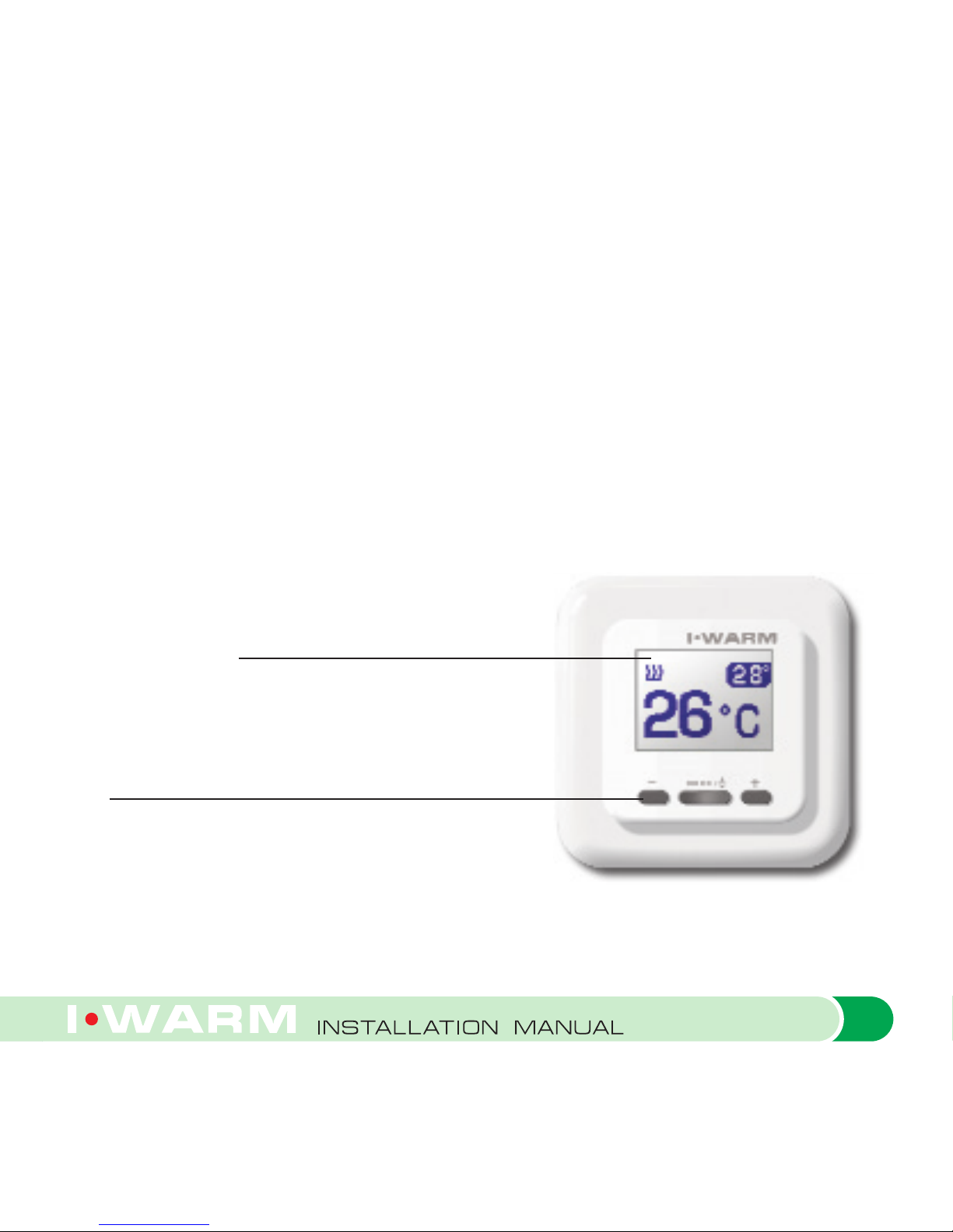
Controls and display . . . . . . . . . . . . . . . . . . . . . . . . . . . . ..7
Air temperature display mode . . . . . . . . . . . . . . . . . . . . . ..8
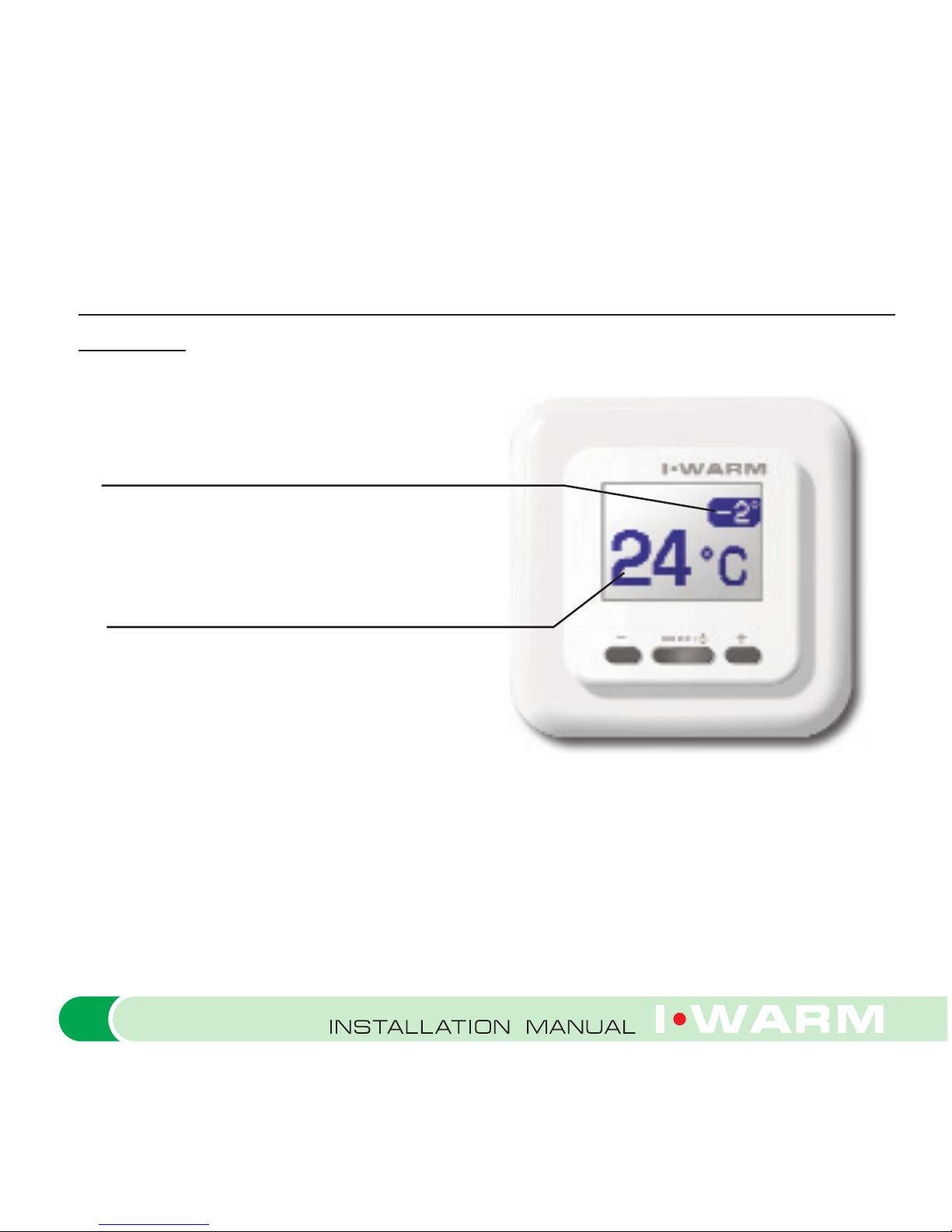
Adjustment of built-in ambient
temperature sensor indicator . . . . . . . . . . . . . . . . . . . . . . .9
Control of heating system operating conditions . . . . . . 11
Manual heating control mode . . . . . . . . . . . . . . . . . . . . . 13
Warranty policy . . . . . . . . . . . . . . . . . . . . . . . . . . . . . . . . 15
Appendix . . . . . . . . . . . . . . . . . . . . . . . . . . . . . . . . . . . . . 16
Delivery set . . . . . . . . . . . . . . . . . . . . . . . . . . . . . . . . . . . .16
Installation manual and wiring diagram . . . . . . . . . . . . . .16
Technical Specifications . . . . . . . . . . . . . . . . . . . . . . . . . .26
Important: The Manufacturer's guarantee does not cover mal-
functions caused by mechanical damage, improper installation,
or exploitation for purposes, or under conditions, not provided
by the user and Installation Manual. Please keep in mind that
2