manuals.online logo
Brands
  1. Home
  2. •
  3. Brands
  4. •
  5. I0JXX
  6. •
  7. Antenna
  8. •
  9. I0JXX 6JXX6 Yagi User manual

I0JXX 6JXX6 Yagi User manual

IØJXX di Donzello Rosanna
Via della Fattoria di Torrenova 3 - 00133 Roma - Italy
( & Fax +39 (0) 6 - 27858223 È+39 3282899664
VAT number: IT09527381009
www.i0jxx.com - [email protected]
Skype: i0jxx.com
6JXX6 Yagi
Item Q.ty Item Q.ty
Stainless steel nut M5 6 Stainless steel bolt M5x40 2
Stainless steel nut M6 1 Stainless steel bolt M5x45 2
Stainless steel nut M8 7 Stainless steel Eyescrew M5 2
Lock washer 8 mm Ø 7 Stainless steel bolt M8x35 2
Flat washer 8 mm Ø 7 Stainless steel bolt M8x90 2
Lock washer 5 mm Ø 6 Stainless steel Turnbuckle 2
Lock washer 6 mm Ø 1 Stainless steel bolt M6x35 1
Flat washer 6 mm Ø 1 Stainless steel bolt M4x20 6
Lock washer 4 mm Ø 6 Stainless steel parker screw 3.5x9.5 11
Stainless steel nut M4 6 Plate PIA40JXX 1
Section boom A 25 mm Ø 115 cm. 1 Plate PIA00JXX 1
Section boom A - B 30 mm Ø 115 cm. 1 Semi-element Ø 12 mm 12
Section boom B - C 35 mm Ø 115 cm. 1 Dipole Hairpin and balun ISO30D_12 1
Section boom C - D 40 mm Ø 115 cm. 1 Insulator ISO25_12 2
Section boom D - E 35 mm Ø 115 cm. 1 Insulator ISO30_12 1
Section boom E - F 30 mm Ø 115 cm. 1 Insulator ISO35_12 2
Section boom F 25 mm Ø 115 cm. 1 Inbuss key 3 mm 1
Dacron rope back 260 cm. 1
Dacron rope front 320 cm. 1 Hairpin 155 mm 1
IØJXX may vary them without any warning
Made in Italy
DL6WU 9 m VE7BQH 8.04 ÷ 7.82 m
E
+ +
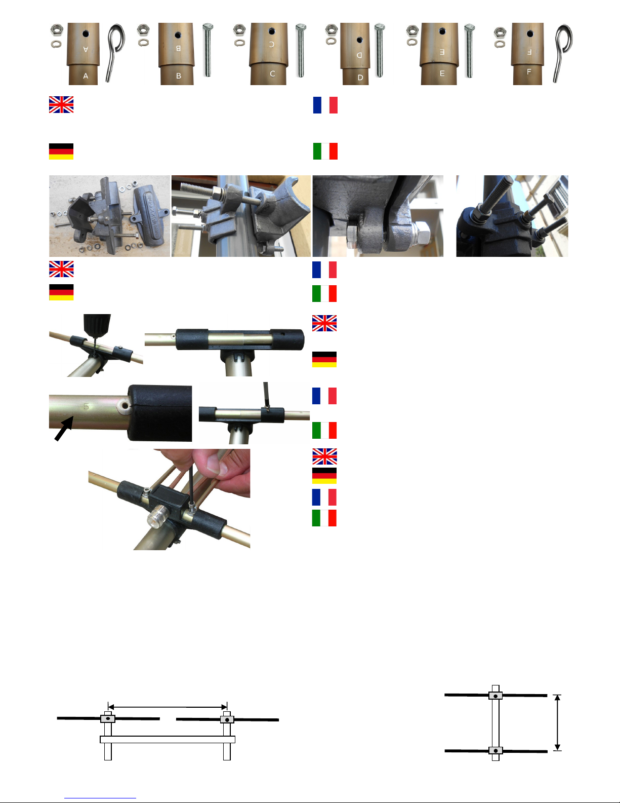
Combine the boom respecting the letters placed at the ends of each section
Insert the screws M5x35 mm washer and nut into the junction points A - A
and D - D then insert the screws M5x40 mm washer and nut, junction points
B - B and C – C
Kombinieren Sie den Boom und achten Sie dabei auf die Buchstaben am
Ende jeder Sektion
Fügen Sie die Schrauben M5x35 mm Unterlegscheibe und Mutter in die Ver-
bindungsstellen A - A und D - D, und die Schrauben M5x40 mm Unterleg-
scheibe und Mutter in den Knotenpunkte B - B und C – C
Unire il boom rispettando le lettere poste alle estremità di ogni singola sezio-
ne
Inserire le viti M5x35 mm rondella e dado, nei punti di giunzione A - A e D -
D, inserire le viti M5x40 mm rondella e dado, nei punti di giunzione B - B e
C - C
Combinez le boom sur les lettres placées aux extrémités de chaque section
Insérez les vis M5x35 mm rondelle et un écrou dans les points de jonction A
- A et D – D puis, insérer les vis M5x40 mm rondelle et un écrou, les points
de jonction B - B et C – C
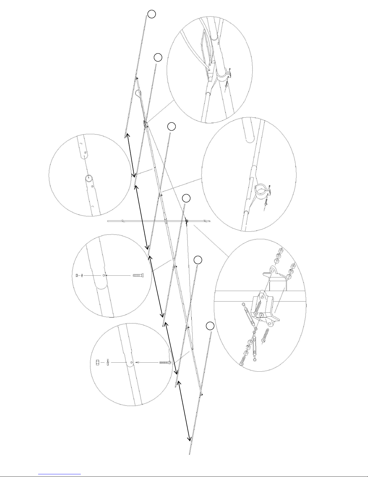
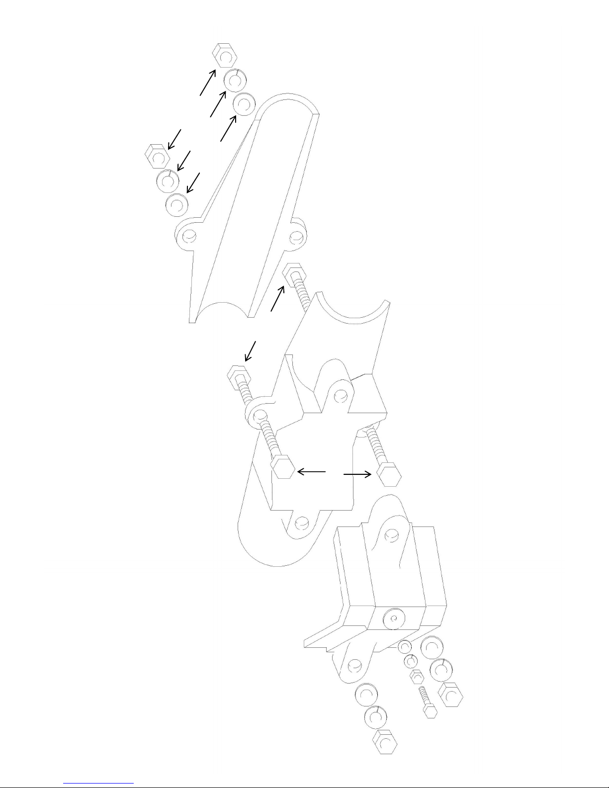
Fixez la plaque de montage entre la flèche et le mât PIA40JXX entre les
éléments 3 – 4
Montieren Sie die Montageplatte zwischen Ausleger und Mast PIA40JXX
zwischen den Elementen 3 – 4
Attach the mounting plate between boom and mast PIA40JXX between
elements 3 – 4
Montare la piastra di fissaggio tra boom e mast PIA40JXX dietro l’elemen-
to 3
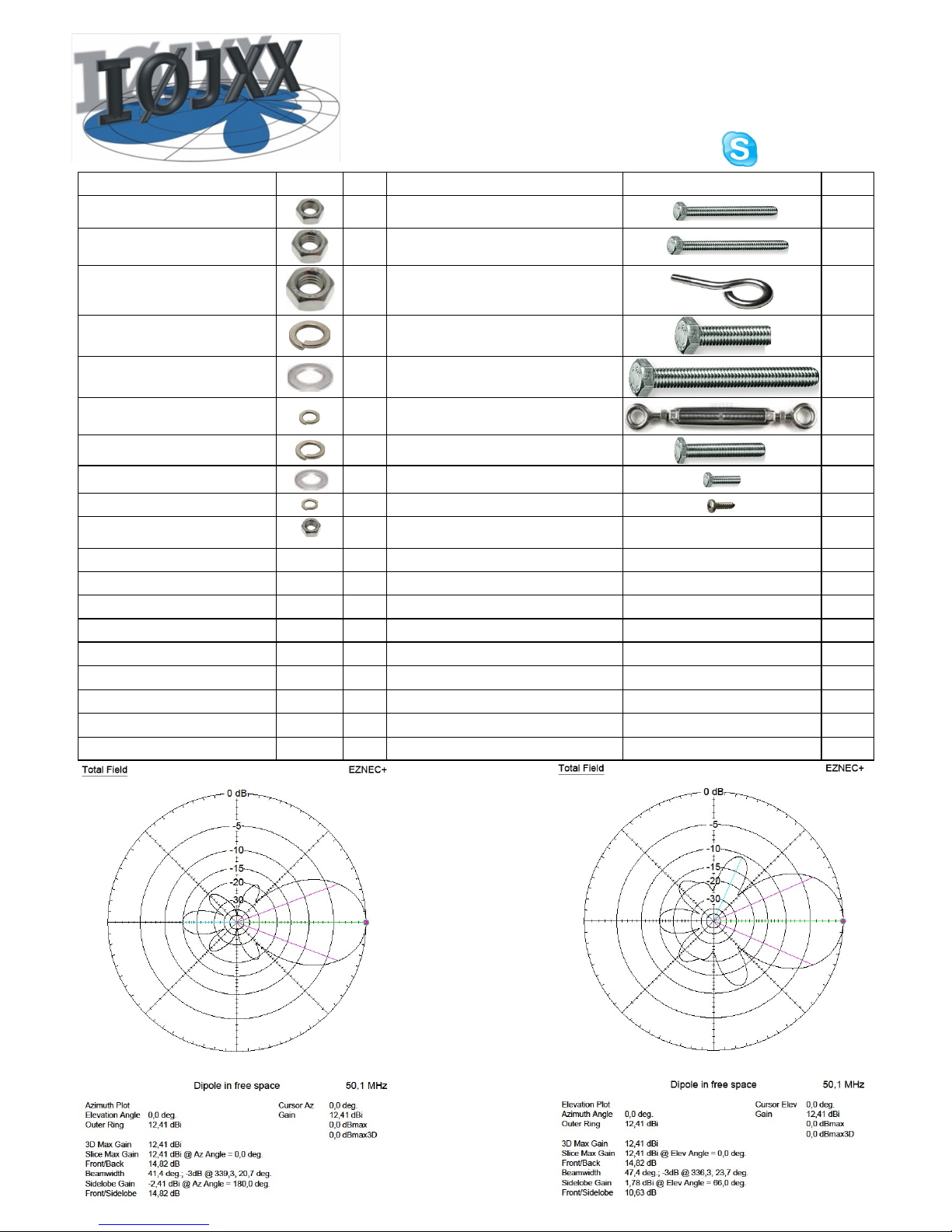
In order to obtain the best results in coupling the antennas, we warmly recommend an adequate antenna stacking calculation which
would allow the best forward gain together with low side lobes. The stacking distance may be calculated with the following formula
from Güenter Hoch DL6WU
On the basis of further studies conducted by Lionel VE7BQH over the antenna stacking argument, a reduction of 5÷10% may be
introduced on stacking distances without noticing significant overall worsening of the characteristics. Do respect the driven element
supplying simmetry to allow anti-phase coupling
5982 5982
Plane E = 38.8° = ——————— = ———— @ 8.46 m (with VE7BQH from 8.04 m to 7.62 m)
2 * sin (41.4 / 2) 0.7069
5982 5982
Plane H = 43.6° = ——————— = ———— @ 7.46 m (with VE7BQH from 7.07 m to 6.7 m)
2 * sin (47.4 / 2) 0.8039
DL6WU
8.05 m
VE7BQH
7.07 ÷ 6.7 m
+
+
H
Stacking
La IØJXX si riserva il diritto, senza alcun preavviso, di modificare
Made in Italy
L
d = ———————
2 * sin ( F / 2 )
Insertion d'éléments comme indiqué sur la figure (voir la figure) spatial et
centré avec les éléments placer sous le boom, comme ça on peut éviter
cumulus d’eau, de glace et de neige
Fügen Sie die Elemente räumig und zentriert hinein und fügen Sie sie mit
den Elementen unter dem Boom zusammen, wie in der Abbildung darge-
stellt (siehe Abbildung). Das sollte die Anhäufung von Wasser, Eis und
Schnee verhindern.
Insert elements as shown in the figure spaced apart and balanced (as
shown in the figure) with the elements standing under the boom, in order
to avoid ponding, ice accretion and snowdrift
Inserire gli elementi come riportato in foto e spaziati centro-centro (vedi
figura), con gli elementi sotto al boom, in modo da evitare l’accumulo di
acqua, ghiaccio e neve
Installez les dipôles comme représenter
Verbinden Sie die Dipole wie abgebildet
Match the dipoles as shown in the figure
Montare il dipolo come indicato in figura
3
IØJXX may vary them without any warning
Made in Italy
www.iØjxx.com
6JXX6
1428
1632
1530 1529
5
4
3
2
1
E
E
B
B
D
D
A
A
C
C
B
B
D
D
F
F
F
F
1224
6
Flat 8
Lock 8
Nut 8
M8 x 90
M8 x 35
M6 x 35
Nut 6
Flat 6
Lock 6
Nut 8
Flat 8
Lock 8
Nut 8 Flat 8
Lock 8
IØJXX may vary them without any warning
Made in Italy
www.iØjxx.com

Popular Antenna manuals by other brands

DIEX DXFS6 manual

DIEX

DIEX DXFS6 manual

Velleman ANTDVBT2 user manual

Velleman

Velleman ANTDVBT2 user manual

Linksys AS1SMA Product data

Linksys

Linksys AS1SMA Product data

Antop AT-500SBS manual

Antop

Antop AT-500SBS manual

Kathrein CAS 06 manual

Kathrein

Kathrein CAS 06 manual

GME AE1000 Information Leaflet

GME

GME AE1000 Information Leaflet

DX Engineering DXE-160VA-1 instructions

DX Engineering

DX Engineering DXE-160VA-1 instructions

Maxview CRANK UP B2590/50SNZ Installation & operating instructions

Maxview

Maxview CRANK UP B2590/50SNZ Installation & operating instructions

PSC PSC 941 Yagi Antenna manual

PSC

PSC PSC 941 Yagi Antenna manual

M2 Antenna Systems 11M5DX quick start guide

M2 Antenna Systems

M2 Antenna Systems 11M5DX quick start guide

CommScope CMAX-OMF-6-43-UWI53 Installation instruction

CommScope

CommScope CMAX-OMF-6-43-UWI53 Installation instruction

KVH Industries TracVision TV3 installation guide

KVH Industries

KVH Industries TracVision TV3 installation guide

Gotting HG G-71915ZA Device description

Gotting

Gotting HG G-71915ZA Device description

DX Engineering RF-PRO-1B manual

DX Engineering

DX Engineering RF-PRO-1B manual

COBHAM Sailor 150 FleetBroadband installation manual

COBHAM

COBHAM Sailor 150 FleetBroadband installation manual

Emos EM-9041 manual

Emos

Emos EM-9041 manual

Embention Veronte T28 manual

Embention

Embention Veronte T28 manual

Sangean ANT 60 instructions

Sangean

Sangean ANT 60 instructions

manuals.online logo
manuals.online logoBrands
  • About & Mission
  • Contact us
  • Privacy Policy
  • Terms and Conditions

Copyright 2025 Manuals.Online. All Rights Reserved.