To activate and secure access to your camera, you must first set the
password for the administrative user account (i3admin).
IMPORTANT: Your camera will remain inactive and inaccessible until
administrative password is set.
Activate your Annexxus 57/77R camera by setting administrative password:
1. Connect your Annexxus 57/77R camera to the Gigabit switch.
2. On your i3 NVR, launch i3 Annexxus Configuration Tool (ACT) v.1.5 or higher.
You can download and install the latest ACT installation package from i3 website:
https://i3international.com/download
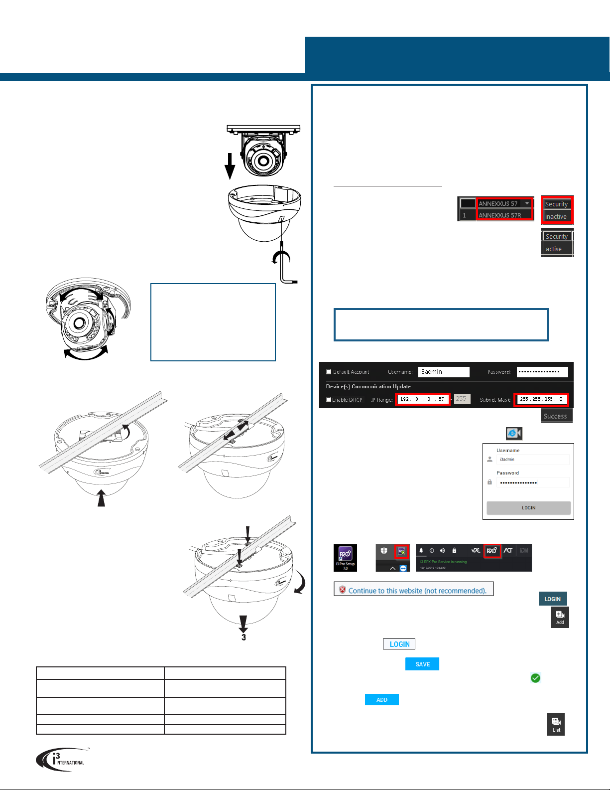
3. In the model drop-down list, select ANNEXXUS 57 or 77.
Security status will say “inactive”.
4. In the Global Camera Settings, click
Set Password
5. In the Set password window, enter the
new password in the Password and Confirm fields. Follow secure
password guidelines. Click OK.
The new administrative password will be assigned to the camera
and the Security status will change to “active”.
Change your Annexxus 57/77R camera’s default IP Address:
Note: Your i3 NVR must have a valid IP address (not APIPA)
6. In Annexxus Configuration Tool, select your Annexxus 57/77R camera in the list.
7. Uncheck “Default Account” and enter “i3admin” into Username field and the
new administrative password (set in Step 6) into Password field.
8. Enter the new IP address and Subnet Mask under Device(s) Communication
Update and click Update.
9. Wait a few moments for a “Success” message in the Result field.
10. Repeat Steps 7-9 for all detected Annexxus 57/77R cameras in the
ACT until each camera has a unique IP address.
11. To confirm your camera’s new IP address, click the IE icon next to each
camera . In the IE browser, enter administrative
Username (i3admin) and (new) Password and
click LOGIN. Annexxus camera interface will be
displayed in the Internet Explorer window. You
should be able to see the camera image on the
screen. If you do not see the camera image on
the screen, call i3 International technical support
team for troubleshooting tips: 1.877.877.7241
ADDING CAMERA TO i3 PRO SETUP v7
1. Launch the i3 Pro Setup from the Desktop or from the SRX-Pro Monitor.
2. In the IE browser, click Continue to this website.
3. Enter your administrator Username and Password and click LOGIN
4. Click on the Add tile.
5. All cameras recognized by i3’s GiPi and ONVIF will be shown in the
UNASSIGNED CAMERAS tab.
6. Select one or more Annexxus 57/77R cameras with the same login credentials
and click LOGIN
7. Enter camera’s Username and the Password (configured in the previous
section) and click SAVE
Login status for your device must now show the green checkmark .
Note: Devices with “Login failed” status will not be added.
8. Click ADD . Your IP devices have been added to i3 Pro Setup and are
recording based on Sensor + Motion schedule.
Change resolution and frame rate for each camera in the List section of the
i3 Pro Setup.
Ax57/77R IP Dome Camera
QUICK START GUIDE
DROP-CEILING INSTALLATION
Ax57/77R camera series comes with pre-installed T-bar ceiling clip (T-Grip) for easy one-
hand indoor installation onto most Standard 1” drop-ceiling grid types.
For easier installation, remove the ceiling tiles to expose the
Supported mounting options
See the table below for additional mounting
options supported by Ax57/77R camera series.
Compatible Mounting Accessories:
B7 - back box for pendant installations
DB60 - goose-neck bracket
DB60CPM - corner/pole mount kit (use with DB60)
Mounting Type Additional Accessories required
Drywall / block wall mount
Surface mount (E.g. drop ceiling tile) None
Pendant Mount
Electrical (Round/Hex, Single Gang) Box B7 / B7v2
Horizontal Wall Mount B7 / B7v2 + DB60
Pole Mount / Corner Mount B7 / B7v2 + DB60 + DB60CPM
i3 INTERNATIONAL INC. 1.866.840.0004
www.i3international.com
6. Cut the cable entry hole in the ceiling tile as required, then
pass the camera’s cable through.
Adjust the lens position for the preferred field of view by
panning, tilting and rotating the camera lens assembly.
Tip: Lift the inner liner for easier lens adjustment.
T-bar grid.
1. Loosen three screws securing the dome cover to camera
module with the Torx bit (provided). Do not completely
remove the screws from the dome cover.
2. Gently pull the dome cover downwards and set aside.
3. Hold the camera firmly against the T-bar grid with the
T-Grip clip on a slight angle, as shown in the
Diagram A.
4. Rotate the camera clockwise until the clip engages with
the T-bar and clicks into place.
5. Slide the camera on the T-bar to adjust the camera
position as shown in the Diagram B (Optional).
The rubberized T-Grip tips will prevent any scratches.
Important: Do not over-rotate the
camera lens assembly beyond the stop
point to prevent twisted, disconnected,
or broken internal cables/components.
3-axis Range Limitations:
Pan range: 355°
Rotate range: 355°
Tilt range: 67°
Diagram B
7. Attach the desiccant to the outside of the camera’s tilt bracket.
8. Replace the camera dome cover and re-tighten 3 silver screws securing the dome
cover to the camera base.
Diagram A
2
1
CAMERA REMOVAL
1. To disengage the T-Grip from the T-bar
grid, press down on both rubberized
T-Grip tips as shown in Diagram C.
2. Rotate the camera counter-clockwise
3. Gently pull the camera down to remove
it from the T-bar.
2
1
1
Diagram C
Camera’s default IP address: 192.0.0.16.
Camera’s default Subnet mask address: 255.255.255.0.
Default User name: i3admin
ACTIVATING CAMERA, CHANGING IP ADDRESS in ACT
Pan
Tilt
Rotate
Or


