PCON-CA/CFA/CB/CFB/CGB/CGFB
CBP/CGBP
,
ACON-CA/CB/CGB, DCON-CA/CB/CGB
First Step Guide Eleventh Edition
Thank you for purchasing our product.
Make sure to read the Safety Guide and detailed Instruction Manual (DVD) included with the product in addition to this
First Step Guide to ensure correct use. This First Step Guide is original manual written by only this product.
Using or copying all or part of this Instruction Manual without permission is prohibited.
The company names, names of products and trademarks of each company shown in the sentences are registered
trademarks.
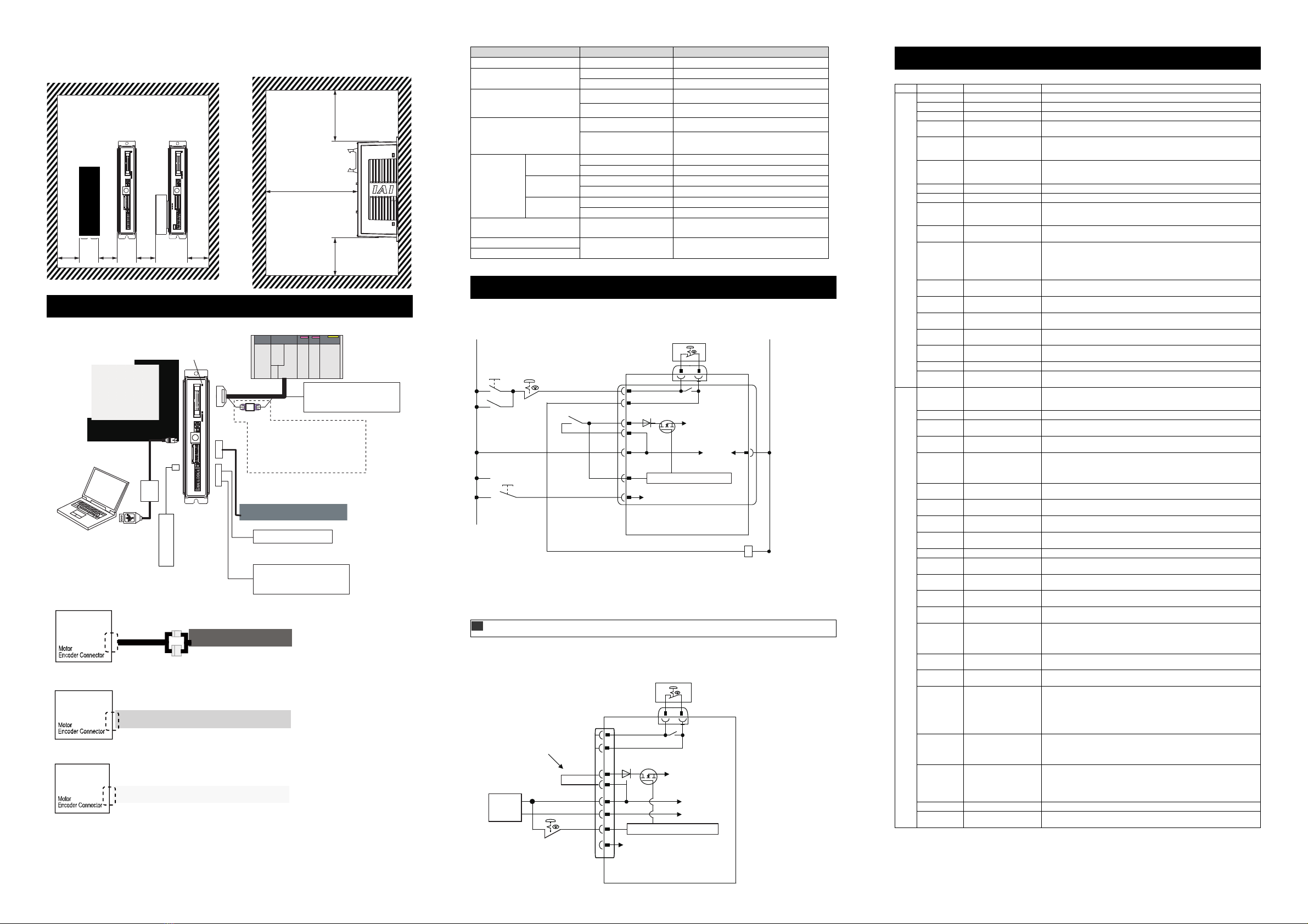
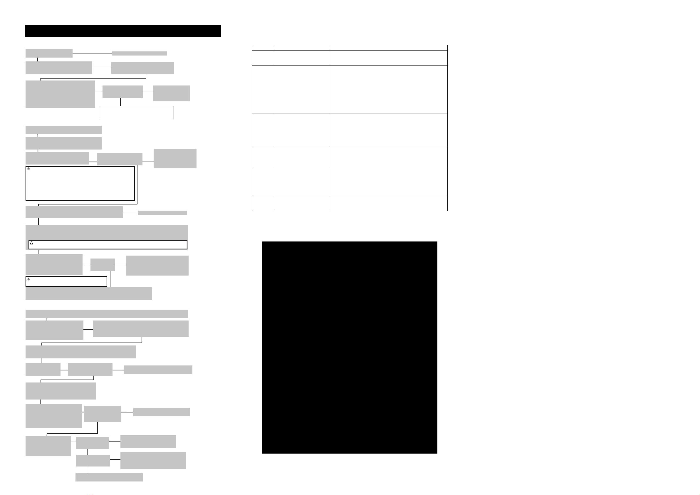
Product Check
The standard configuration of this product is comprised of the following parts.
If you find any fault with the product you have received, or any missing parts, contact us or our distributor.
1. Parts
No. Part Name Model Reference
1 Controller Main Body Refer to “How to read the model plate”,
“How to read the model of the controller”
Accessories
2 I/O Flat Cable CB-PAC-PIO□□□ □□□shows the cable length
3 Power Connector FMC1.5/8-ST-3.5 (Supplier : PHOENIX CONTACT) Recommended cable size
AWG16 to 20
1.25 to 0.5mm2
4 Dummy plug DP-5 For the safety category
compliant t
pe
5 Absolute Battery (Option) AB-7 or SEP-ABU* If applicable for Simple
Absolute T
pe
6 Serial Absolute Battery (Option) AB-5 If applicable for Serial Absolute
T
pe
for ACON onl
7 First Step Guide
8 Instruction Manual
DVD
9 Safet
Guide
2. Teaching Tool (to be purchased separately)
A teaching tool such as PC software is necessary when performing the setup for position setting, parameter
setting, etc. that can only be done on the teaching tool.
Please prepare either of the following teaching tools.
No. Part Name Model
1 PC teaching software (equipped with USB conversion adaptor + USB cable + external device
communication cable
IA-OS-C
2 PC teaching software (equipped with RS232C conversion adaptor + external device
communication cable
RCM-101-MW
3 PC teaching software (equipped with USB conversion adaptor + USB cable + external
device communication cable
RCM-101-USB
4 Touch Panel Teaching TB-01/D/DR
5 Touch Panel Teaching TB-02/D
6 Data Setter TB-03
3. Instruction Manuals related to this product, which are contained in the Instruction Manual (DVD).
No. Name Manual No.
1 PCON-CA/CFA Controller Instruction Manual ME0289
2 PCON-CB/CFB Controller Instruction Manual ME0342
3 ACON-CA, DCON-CA Controller Instruction Manual ME0326
4 ACON-CB Series Contoroller, DCON-CB Series Contorolle
Inst
uction Manual ME0343
5 PC Software RCM-101-MW/ RCM-101-USB Instruction Manual ME0155
6 Touch Panel Teachin
TB-01 Applicable for Position Controlle
Instruction Manual ME0324
7 Touch Panel Teachin
TB-02 Applicable for Position Controller Instruction Manual ME0355
8 Data Setter TB-03 Position Controller, Wired Link Instruction Manual ME0376
9 Instruction Manual for the Serial Communication [fo
Modbus] ME0162
10 CC-Link Instruction Manual ME0254
11 DeviceNet Instruction Manual ME0256
12 PROFIBUS-DP Instruction Manual ME0258
13 CompoNet Instruction Manual ME0220
14 MECHATROLINK-Ⅰ/ⅡInstruction Manual ME0221
15 EtherCAT Instruction Manual ME0273
16 EtherNet/IP Instruction Manual ME0278
17 PROFINET-IO Instruction Manual ME0333
18 MECHATROLINK-ⅢInstruction Manual ME0317
4. How to read the model plate
5. How to read the model of the controller
PCON
PCON-CA-56P WAI-NP-2-0-ABU-DN-**
ACON
ACON-CA-30 I-NP-2-0-AB-DN-**
DCON
DCON-CA-3 I-NP-2-0-DN-**
Basic Specifications
PCON List of Specifications
Item Description
PCON-CA/CB/CGB/CBP/CGBP PCON-CFA/CFB/CGFB
Number of controlled axes 1-axis
Power-supply Voltage 24V DC 10%
Load
Capacity
(including
control side
current
consumption)
(Note1)
RCP2
RCP3
Motor
Type
20P, 28P, 28SP MAX. 1A
42
, 56P MAX. 2.2A
60P, 86P MAX. 6A
RCP4
RCP5
RCP6
Motor
Type
28P, 35P, 42P,
56P
High-thrust function
is disabled MAX.2.2A
High-thrust function
is enabled
Rated 3.5A /
MAX. 4.2A
56SP, 60P, 86P MAX. 6A
Power Supply for Electromagnetic Brake
for actuator equipped with brake
24V DC 10% 0.15A (MAX.)
Heat Generation RCP2, RCP3 5W 26.4W
RCP4 to RCP6 3W
Rush Cur
en
(Note2) 8.3A 10A
Transient Power Cutoff Durability MAX. 500s
Motor Control S
stem Weak field-ma
net vector control
Corresponding
Encoder
RCP2 to RCP5 Incremental Encode
, Batter
-less Absolute Encode
Resolution 800 pulse/rev
RCP6 Batter
-less Encoder Resolution 8192 pulse/rev
Actuator Cable Len
th MAX. 20m
Serial Communication Interface
(SIO Port)
RS485 : 1 channel (based on Modbus Protocol RTU/ASCII)
Speed : 9.6 to 230.4Kbps
Control available with serial communication in the modes other than the pulse
train
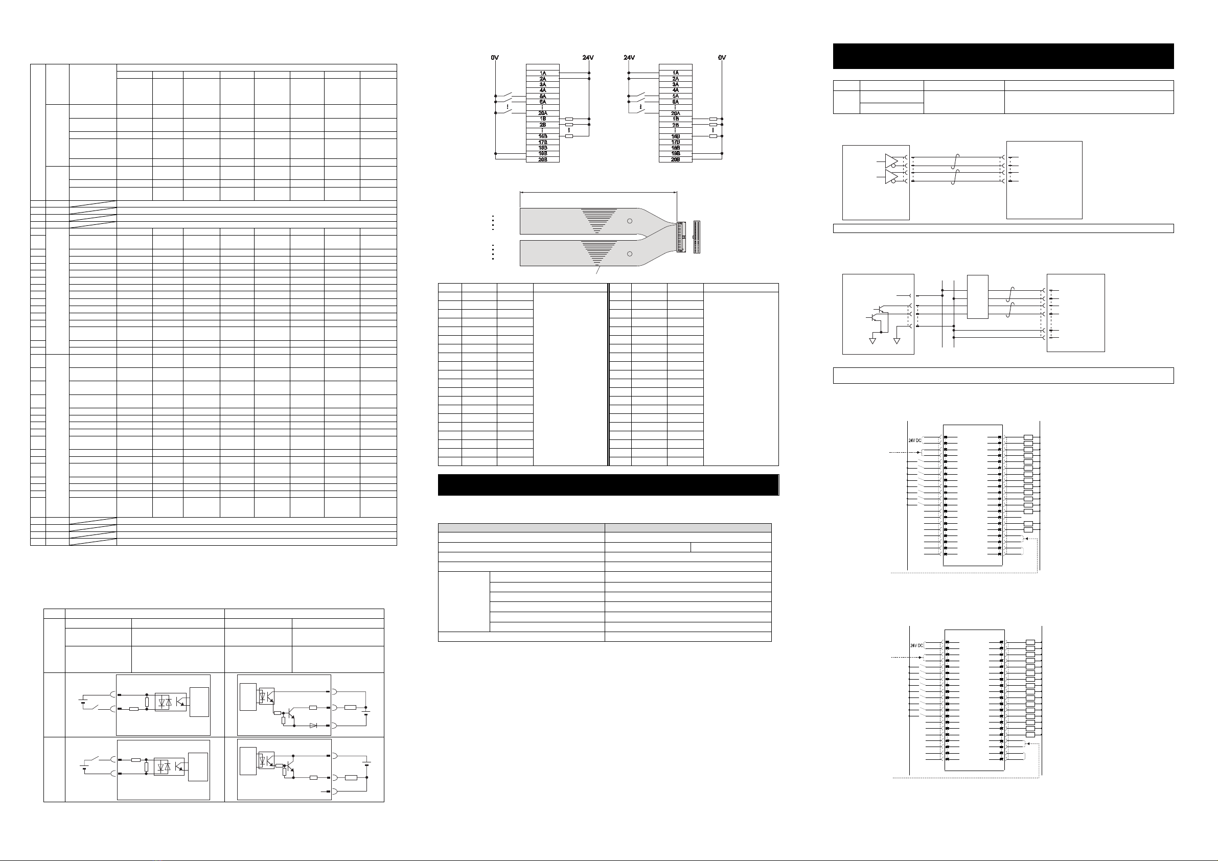
External Interface PIO Type Signal I/O dedicated for 24V DC (selected from NPN/PNP) … Input 16 points
max., output 16 points max.
Cable len
th MAX. 10m
Fieldbus Type DeviceNet, CC-Link, PROFIBUS-DP, CompoNet, MECHATROLINK-Ⅰ/Ⅱ,
EtherCAT, EtherNet/IP, PROFINET-IO, MECHATROLINK-Ⅲ(Except for
PCON-CA/CFA/CBP/CGBP
Loadcell Interface
dedicated for PCON-CBP/CGBP
RS485 Communication
Data Settin
and Inpu
PC Software, Touch Panel Teachin
, Teachin
Pendant, Data Sette
Data Retention Memory Saves position data and parameters to non-volatile memory
There is no limitation in number of writin
Operation Mode Positioner Mode/Pulse Train Control Mode
selected b
parameter settin
Number of Positions in Positioner Mode Standard 64 points, MAX. 512 points (PIO Specification)
(Note) Number of positions differs depending on the selection in PIO pattern
and fieldbus operation mode.
Pulse Train
Interface
Input Pulse Frequency Differential System (Line Driver System) : MAX. 200kpps
Cable len
th MAX. 10m
Open Collector System : Not applicable.
* If the host applies the open collector output, prepare AK-04 (option) separately
to convert to the differential t
pe.
Command Pulse
Multiplying Factor
Electrical Gear : A/B
1/50 A/B 50/1
Setting Range of A and B (set to parameter) : 1 to 4096
Feedback Pulse Output None
LED Display
(mounted on Front Panel)
SV (GN)/ALM (RD) : Servo ON/Alarm generated
STS0 to 3 : Status display
RDY (GN)/ALM (RD) : Absolute function in normal / absolute function error (for
the simple absolute type)
1, 0 (GN) (RD) : Absolute function status display (for the simple absolute
t
pe
Electromagnetic Brake Compulsory
Release Switch
mounted on Front Panel
Switching NOM (standard)/BK RLS (compulsory release)
Insulation Resistance 500V DC 10Mor more
Protection Function a
ainst Electric Shoc
Class I basic insulation
Weight
(Note3)
Incremental Type Screw fixed type : 250g or less
DIN rail fixed t
pe : 285
or less
Screw fixed type : 270g or less
DIN rail fixed t
pe : 305
or less
Simple Absolute Type
includin
190
for batter
Screw fixed type : 450g or less
DIN rail fixed t
pe : 485
or less
Coolin
Method Natural ai
-coolin
Forced ai
-coolin
External dimensions Screw fixed type : 35W×178.5H×69.6D
DIN rail fixed t
pe : 35W×185H×78.1D
Screw fixed type : 35W×190H×69.6D
DIN rail fixed t
pe : 35W×196.5H×78.1D
Environment
Surrounding Air
Temperature
0 to 40C
Surroundin
Humidit
5%RH to 85%RH or less
There should be no condensation or freeze
Surrounding
Environmen
[Refer to Installation Environment]
Surrounding Storage
Temperature
-20 to 70C (Excluding battery)
Usa
e Altitude 1000m or less
Protection Class IP20
Vibration Durability Frequency 10 to 57Hz / Swing width : 0.075mm
Frequency 57 to 150Hz / Acceleration 9.8m/s2
XYZ directions Sweep time : 10 minutes Number of sweep : 10 times
Note1 Value increases in 0.3A for Fieldbus Type
Note2 In-rush current will flow for approximately 5ms after the power is turned ON (at 40C).
Note that the value of in-rush current differs depending on the impedance of the power supply line.
Note3 Value increases in 30g for Fieldbus Type.
Warning : Operation of this equipment requires detailed installation and operation instructions which are
provided on the DVD Manual included in the box this device was packaged in. It should be retained
with this device at all times.
A hardcopy of the Manual can be requested by contacting your nearest IAI Sales Office listed at
the back cove
of the Instruction Manual or on the First Step Guide.
<Series>
<Type>
CA/CB : Standard Type
CFA/CFB : High-Thrust Actuator
Connection Type
CGB
:
Safety Categories Complied Type
CGFB
:High-Thrust Actuator
Connection Safety Categories
Complied Type
CBP
:Pulse Pressing Connection
Applicable Type
CGBP
:Pulse Pressing Connection
Safety Categories Complied Type
<Detail of Connected Axis>
[Motor Type]
20P : 20□pulse motor, 20SP : 20□pulse motor
28P : 28□pulse motor, 28SP : 28□pulse motor
35P : 35□pulse motor, 42P : 42□pulse motor
42SP : 42□pulse motor, 56P : 56□pulse motor
56SP : 56□pulse motor, 60P :60□pulse motor
86P : 86□pulse motor
[Encoder Type]
WAI : Incremental / Battery-less Absolute Shared
SA : Sim
le Absolute
<Identification for IAI use only>
* There is no identification in some cases.
<Type of Installation>
(Not Specified) : Screw Attachment Type
DN : DIN Rail Mounting Type
<Applicable to Simplified Absolute Unit>
(Not Specified): Incremental
/ Battery-less Absolute
AB : Simple Absolute Type
(With the Absolute Battery)
ABU : Simple Absolute Type
(With the Absolute Battery Unit
(SEP-ABU))
ABUN : Simple Absolute Type
(With no Absolute Battery)
<Power-supply Voltage>
0 : 24V DC
<I/O Cable Length>
0 : Equipped with no cable
2 : 2m (Standard)
3 : 3m
5 : 5m
<Series>
<Type>
CA/CB : Standard Type
CGB : Safety Categories Complied Type
<Detail of Connected Axis>
[Motor Type]
2 : 2W AC servo motor
5 : 5W AC servo motor
10 : 10W AC servo motor
20S : 20W AC servo motor
20 : 20W AC servo motor
30 : 30W AC servo motor
[Encoder Type]
WAI : Incremental / Battery-less Absolute
shared (CB only)
I : Incremental A : Absolute
[Option]
HA : High Acceleration/Deceleration Type
LA : Low Power Consumption Type
No description : Standard Type
<I/O Type>
NP : NPN Type (Sync. Type) (Standard),
PN : PNP Type (Source Type),
PLN : Pulse Train Control NPN Type (Sync. Type),
PLP : Pulse Train Control PNP Type (Source Type),
DV : DeviceNet Connection Type, CC : CC-Link Connection Type
PR : PROFIBUS-DP Connection Type, CN : CompoNet Connection Type
PRT : PROFINET-IO Connection Type, EC : EtherCAT Connection Type
EP : EtherNet/IP Connection Type ML : MECHATROLINK-Ⅰ/ⅡConnection Type
ML3 : MECHATROLINK-ⅢConnection Type (Except for ACON-CA)
<Identification for IAI use only>
* There is no identification in some cases.
<Type of Installation>
(Not Specified) : Screw Attachment Type
DN : DIN Rail Mounting Type
<Applicable to Simplified Absolute Unit>
AB : Simple Absolute Type
(With the Absolute Battery)
ABU : Simple Absolute Type
(With the Absolute Battery Unit
(SEP-ABU))
ABUN : Simple Absolute Type
(With no Absolute Battery)
<Power-supply Voltage>
0 : 24V DC
<I/O Cable Length>
0 : Equipped with no cable
2 : 2m (Standard)
3 : 3m
5 : 5m
<Series>
<Type>
CA/CB : Standard Type
CGB : Safety Categories Complied Type
<Detail of Connected Axis>
[Motor Type]
3 : 2.5W DC Brushless motor
[Encoder Type]
I : Incremental
<I/O Type>
NP : NPN Type (Sync. Type) (Standard),
PN : PNP Type (Source Type),
PLN : Pulse Train Control NPN Type (Sync. Type),
PLP : Pulse Train Control PNP Type (Source Type),
DV : DeviceNet Connection Type, CC : CC-Link Connection Type
PR : PROFIBUS-DP Connection Type, CN : CompoNet Connection Type
PRT : PROFINET-IO Connection Type, EC : EtherCAT Connection Type
EP : EtherNet/IP Connection Type, ML : MECHATROLINK-Ⅰ/ⅡConnection Type
ML3 : MECHATROLINK-ⅢConnection Type (Except for DCON-CA)
<Identification for IAI use only>
* There is no identification in some cases.
<Type of Installation>
(Not Specified) : Screw Attachment Type
DN : DIN Rail Mounting Type
<Power-supply Voltage>
0 : 24V DC
<I/O Cable Length>
0 : Equipped with no cable
2 : 2m (Standard)
3 : 3m
5 : 5m
Serial numbe
Model
Model
SER NO.
Input
Output
Actuator
**
CAUTION: Connect the wiring correctly and
properly, use IAI specified cables
or min 60°C Cu wire.
IP20
*********
*********
DC24V A
0-24Vac,3ph,0-333Hz, A
*****
<I/O Type>
NP : NPN Type (Sync. Type) (Standard),
PN : PNP Type (Source Type),
PLN : Pulse Train Control NPN Type (Sync. Type PCON-CBP/CGBP Except)
PLP : Pulse Train Control PNP Type (Source Type PCON-CBP/CGBP Except)
DV : DeviceNet Connection Type, CC : CC-Link Connection Type
PR : PROFIBUS-DP Connection Type, CN : CompoNet Connection Type
PRT : PROFINET-IO Connection Type, EC : EtherCAT Connection Type
EP : EtherNet/IP Connection Type, ML : MECHATROLINK-Ⅰ/ⅡConnection Type
ML3 : MECHATROLINK-ⅢConnection Type (Except for PCON-CA/CFA/CBP/CGBP)
*PCON-CBP/CGBP is not applicable for
the simple absolute type.