IAI Robo Cylinder CON-T User manual

Teaching Pendant
Instruction Manual Tenth Edition
CON-T, CON-TG,
CON-TGS
IAI Corporation


[Important]
•This Instruction Manual is original.
• TheproductcannotbeoperatedinanywayunlessexpresslyspeciedinthisInstructionManual.
IAIshallassumenoresponsibilityfortheoutcomeofanyoperationnotspeciedherein.
•Information contained in this Instruction Manual is subject to change without notice for the
purpose of product improvement.
•If you have any question or comment regarding the content of this manual, please contact the
IAIsalesofcenearyou.
•Using or copying all or part of this Instruction Manual without permission is prohibited.
•The company names, names of products and trademarks of each company shown in the
sentences are registered trademarks.
Please Read Before Use
Thank you for purchasing our product.
This Instruction Manual describes all necessary information items to operate this product safely such
as the operation procedure, structure and maintenance procedure.
Before the operation, read this manual carefully and fully understand it to operate this product safely.
The enclosed CD/DVD in this product package includes the Instruction Manual for this product.
For the operation of this product, print out the necessary sections in the Instruction Manual or display
them using the personal computer.
After reading through this manual, keep this Instruction Manual at hand so that the operator of this
product can read it whenever necessary.


CAUTION
Disconnection of the Teaching Pendant from the PCON /
ACON / SCON Controller / ERC2
* After disconnecting the Teaching Pendant from the PCON / ACON / SCON controller / ERC2 with the
AUTO/MANU switch, always turn the AUTO/MANU switch to AUTO.
* For the PCON / ACON controller / ERC2 without AUTO/MANU switch, always set the TP Operation
Mode to “MONIT 2” before disconnecting the Teaching Pendant from the controller.
(Refer to “6.10 TP Operation Mode.”)
(Note) When the controller is set by connecting the Teaching Pendant to the PCON / ACON /
controller without an AUTO/MANU switch, the conditions shown below occur.
When the controller is set by connecting the Teaching Pendant to the gateway unit/SIO
converter, the conditions shown below occur.
●IftheTeachingPendantisdisconnectedwhilethesettingof“TEACH1”or“TEACH2”
remains, I/O will become invalid and control from PLC will become impossible.
●IftheTeachingPendantisdisconnectedwhilethesettingof“MONIT1”remains,the
maximum speed will become the safety speed set for the parameter regardless of a
command from PLC.

5
CAUTION
Precautions in Teaching Pendant Connection
When the controller’s power input “+” terminal is grounded, the applicable teaching
pendant model cannot be connected.
When it is connected, the normal power is not supplied and it might cause the breakdown
of the teaching pendant.
Applicable Models: CON-T, RCM-T, RCM-TD
Teaching Pendant
Controller
+24VPower
DO NOT CONNECT

5
Support Models
The following are the versions to which we have started support:
Table 1 List 1 of Support Models
Model No. CON-T
Supported/Unsupported
CON-TG/TGS
Supported/Unsupported Support Started Version
RCP *1 ○× V1.00
RCS *1 ○× V1.00
E-Con *1 ○× V1.00
RCP2 *1 ○× V1.00
ERC *2 *2 V1.00
ERC2 *2 *2 V1.00
PCON ○ ○ V1.00
ACON ○ ○ V1.00
ACON-CA ○ ○ V1.20
DCON-CA ○ ○ V1.20
SCON-C ○ ○ V1.00
SCON-CA ○ ○ V1.10
PCON-CA ○ ○ V1.13
ERC3 (CON
Mode (CN)) ○ ○ V1.13
*1: CON-T Teaching Pendant also supports the RCP, RCS, E-Con and RCP2 controllers.
*2:ForthesupportfortheERC2andERC,conrmitusingthesealattachedontheleftside(viewedfrom
the rear) of the cover.
Description on ERC2 Seal
I/O Type Unsupported Supported
NP NP U5 M NP T1 4904
PN PN U3 M PN T1 4904
Description on ERC Seal
I/O Type Unsupported Supported
NP T1 T1 4904
PN EP T1 EP T1 4904
* Check the model to connect and the version of the Teaching Pendant. If any unsupported model is
connected, unexpected movement may occur.
* ERC2, PCON, ACON, SCON, or DCON cannot be used by linking to any model of those shown in
*1.


Table of Contents
Safety Guide.................................................................................................................1
1. Safety Precautions ..........................................................................................9
2. Warranty ..............................................................................................................10
2.1 Warranty Period .................................................................................................................10
2.2 Scope of the Warranty .......................................................................................................10
2.3 HonoringtheWarranty .......................................................................................................10
2.4 Limited Liability....................................................................................................................11
2.5 Conditions of Conformance with Applicable Standards/Regulations, Etc.,
and Applications..................................................................................................................11
2.6 Other Items Excluded from Warranty..................................................................................11
3. Application Environment .....................................................................................12
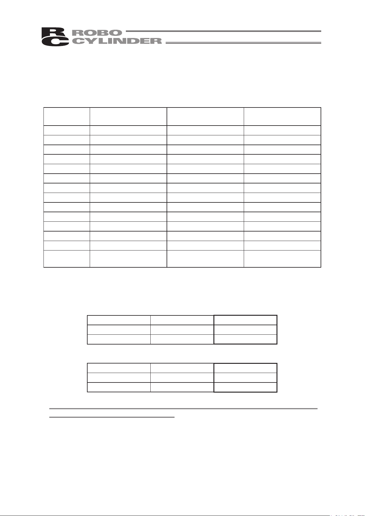
4. Functions and Specications of Teaching Pendant ..............................................13
4.1 Specications ......................................................................................................................13
4.2 External View .....................................................................................................................14
4.3 Description of Each Part .....................................................................................................15
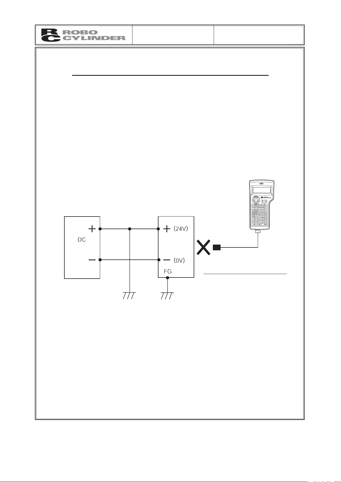
5. Connection With the Controller............................................................................20
5.1 Connection with the Teaching Pendant ..............................................................................20
5.2 HowtoDisengagetheTeachingPendant...........................................................................20
5.3 Connection between CON-TG/TGS and the Controller ......................................................21
6. Operation: Mode Flow Chart................................................................................27
(1) Positioner (PCON-PL/PO, ACON-PL/PO and SCON:
Mode other than the Pulse Train Mode).............................27
(2) Pulse Train (PCON-PL/PO, ACON-PL/PO and SCON: Pulse Train Mode) ............................28
6.1 Initial Screen and TP Operation Mode Screen During Power - UP ....................................29
6.2 Controller Selection (when using multiple units) ................................................................31
6.3 Operation Mode Selection ..................................................................................................32
6.4 Edit/Teaching .....................................................................................................................33
6.4.1 PCON, ACON, SCON, DCON, ERC2 or ERC3 ………………………………………… 33
6.4.2 RCP, RCS, E-Con or RCP2 ……………………………………………………………… 35
6.5 Position Data Table Contents ............................................................................................37
6.5.1 Position Data Table Contents for PCON, ACON, SCON, DCON, ERC2 or ERC3 … 37
6.5.2 Position Data Table Contents for RCP, RCS, E-Con and RCP2 …………………… 44
6.5.3 Data New Input……………………………………………………………………………… 46
6.5.4 DataModication …………………………………………………………………………… 64
6.5.5 Clear All Clear …………………………………………………………………………… 64

6.5.6 Move ………………………………………………………………………………………… 67
6.5.7 Servo ON/OFF …………………………………………………………………………… 74
6.5.8 Pulse Train (PCON-PL/PO, ACON-PL/PO, SCON: Pulse Train Mode,
ERC3: Pulse Train Mode) Based Jogging ……………………………………………… 75
6.6 Monitor ...............................................................................................................................76
6.7 Error List .............................................................................................................................84
6.8 User Parameters ................................................................................................................85
6.8.1 User Parameters …………………………………………………………………………… 85
6.8.2 Pause, Servo ON Input Enable and Disable Setting …………………………………… 91
6.9 User Adjustment .................................................................................................................92
6.9.1 HomingOperation,AxisNumberSetting,CalibrationandTimeSetting …………… 92
6.9.2 Software Reset……………………………………………………………………………… 94
6.9.3 Error List Clear ……………………………………………………………………………… 95
6.10 TP Operation Mode ............................................................................................................96
6.11 End .....................................................................................................................................98
7. Message Area .....................................................................................................99
7.1 Warning Label Error (Code No. 000h - 07Fh) ....................................................................99
7.2 Teaching Pendant Message Level Error ..........................................................................100
7.3 Controller Error .................................................................................................................100
* Appendix
Parameter (Shipment) Initialization Method .............................................................101
Teaching Pendant Error Messages..........................................................................102
ChangeHistory.........................................................................................................105

1
Safety Precautions for Our Products
The common safety precautions for the use of any of our robots in each operation.
No. Operation
Description Description
1 Model Selection ●Thisproducthasnotbeenplannedanddesignedfortheapplication
where high level of safety is required, so the guarantee of the protection of
human life is impossible. Accordingly, do not use it in any of the following
applications.
1) Medical equipment used to maintain, control or otherwise affect human
life or physical health.
2) Mechanisms and machinery designed for the purpose of moving or
transporting people (For vehicle, railway facility or air navigation facility)
3) Important safety parts of machinery (Safety device, etc.)
●Donotusetheproductoutsidethespecications.Failuretodosomay
considerably shorten the life of the product.
●Donotuseitinanyofthefollowingenvironments.
1) Locationwherethereisanyinammablegas,inammableobjector
explosive
2) Place with potential exposure to radiation
3) Location with the ambient temperature or relative humidity exceeding
thespecicationrange
4) Location where radiant heat is added from direct sunlight or other large
heat source
5) Location where condensation occurs due to abrupt temperature
changes
6) Location where there is any corrosive gas (sulfuric acid or hydrochloric
acid)
7) Locationexposedtosignicantamountofdust,saltorironpowder
8) Location subject to direct vibration or impact
●Foranactuatorusedinverticalorientation,selectamodelwhichis
equipped with a brake. If selecting a model with no brake, the moving part
may drop when the power is turned OFF and may cause an accident such
as an injury or damage on the work piece.
Safety Guide
“Safety Guide” has been written to use the machine safely and so prevent personal injury or property
damage beforehand. Make sure to read it before the operation of this product.

2
No. Operation
Description Description
2 Transportation ●Whencarryingaheavyobject,dotheworkwithtwoormorepersonsor
utilize equipment such as crane.
●Whentheworkiscarriedoutwith2ormorepersons,makeitclearwhois
to be the leader and who to be the follower(s) and communicate well with
each other to ensure the safety of the workers.
●Whenintransportation,considerwellaboutthepositionstohold,weight
and weight balance and pay special attention to the carried object so it
would not get hit or dropped.
●Transportitusinganappropriatetransportationmeasure.
The actuators available for transportation with a crane have eyebolts
attached or there are tapped holes to attach bolts. Follow the instructions
in the instruction manual for each model.
●Donotsteporsitonthepackage.
●Donotputanyheavythingthatcandeformthepackage,onit.
●Whenusingacranecapableof1tormoreofweight,haveanoperator
whohasqualicationsforcraneoperationandslingwork.
●Whenusingacraneorequivalentequipments,makesurenottohanga
load that weighs more than the equipment’s capability limit.
●Useahookthatissuitablefortheload.Considerthesafetyfactorofthe
hook in such factors as shear strength.
●Donotgetontheloadthatishungonacrane.
●Donotleavealoadhungupwithacrane.
●Donotstandundertheloadthatishungupwithacrane.
3 Storage and
Preservation
●Thestorageandpreservationenvironmentconformstotheinstallation
environment.However,especiallygiveconsiderationtothepreventionof
condensation.
●Storetheproductswithaconsiderationnottofallthemoverordropdueto
an act of God such as earthquake.
4 Installation and
Start
(1) Installation of Robot Main Body and Controller, etc.
●Makesuretosecurelyholdandxtheproduct(includingtheworkpart).A
fall, drop or abnormal motion of the product may cause a damage or injury.
Also, be equipped for a fall-over or drop due to an act of God such as
earthquake.
●Donotgetonorputanythingontheproduct.Failuretodosomay
cause an accidental fall, injury or damage to the product due to a drop
of anything, malfunction of the product, performance degradation, or
shortening of its life.
●Whenusingtheproductinanyoftheplacesspeciedbelow,providea
sufcientshield.
1) Location where electric noise is generated
2) Locationwherehighelectricalormagneticeldispresent
3) Location with the mains or power lines passing nearby
4) Location where the product may come in contact with water, oil or
chemical droplets

3
No. Operation
Description Description
4 Installation and
Start
(2) Cable Wiring
●Useourcompany’sgenuinecablesforconnectingbetweentheactuator
and controller, and for the teaching tool.
●Donotscratchonthecable.Donotbenditforcibly.Donotpullit.Donot
coil it around. Do not insert it. Do not put any heavy thing on it. Failure to
dosomaycauseare,electricshockormalfunctionduetoleakageor
continuity error.
●Performthewiringfortheproduct,afterturningOFFthepowertotheunit,
so that there is no wiring error.
●Whenthedirectcurrentpower(+24V)isconnected,takethegreatcareof
the directions of positive and negative poles. If the connection direction is
notcorrect,itmightcauseare,productbreakdownormalfunction.
●Connectthecableconnectorsecurelysothatthereisnodisconnectionor
looseness.Failuretodosomaycauseare,electricshockormalfunction
of the product.
●Nevercutand/orreconnectthecablessuppliedwiththeproductforthe
purpose of extending or shortening the cable length. Failure to do so may
causetheproducttomalfunctionorcausere.
(3) Grounding
●Thegroundingoperationshouldbeperformedtopreventanelectricshock
or electrostatic charge, enhance the noise-resistance ability and control
the unnecessary electromagnetic radiation.
●ForthegroundterminalontheACpowercableofthecontrollerandthe
grounding plate in the control panel, make sure to use a twisted pair cable
with wire thickness 0.5mm2(AWG20 or equivalent) or more for grounding
work. For security grounding, it is necessary to select an appropriate
wirethicknesssuitablefortheload.Performwiringthatsatisesthe
specications(electricalequipmenttechnicalstandards).
●PerformClassDGrounding(formerClass3Groundingwithground
resistance 100Wor below).

4
No. Operation
Description Description
4 Installation and
Start
(4) Safety Measures
●Whentheworkiscarriedoutwith2ormorepersons,makeitclearwhois
to be the leader and who to be the follower(s) and communicate well with
each other to ensure the safety of the workers.
●Whentheproductisunderoperationorinthereadymode,takethesafety
measures (such as the installation of safety and protection fence) so that
nobody can enter the area within the robot’s movable range. When the
robot under operation is touched, it may result in death or serious injury.
●Makesuretoinstalltheemergencystopcircuitsothattheunitcanbe
stopped immediately in an emergency during the unit operation.
●Takethesafetymeasurenottostartuptheunitonlywiththepowerturning
ON. Failure to do so may start up the machine suddenly and cause an
injury or damage to the product.
●Takethesafetymeasurenottostartupthemachineonlywiththe
emergency stop cancellation or recovery after the power failure. Failure
to do so may result in an electric shock or injury due to unexpected power
input.
●Whentheinstallationoradjustmentoperationistobeperformed,give
clear warnings such as “Under Operation; Do not turn ON the power!” etc.
Sudden power input may cause an electric shock or injury.
●Takethemeasuresothattheworkpartisnotdroppedinpowerfailureor
emergency stop.
●Wearprotectiongloves,goggleorsafetyshoes,asnecessary,tosecure
safety.
●Donotinsertangerorobjectintheopeningsintheproduct.Failuretodo
somaycauseaninjury,electricshock,damagetotheproductorre.
●Whenreleasingthebrakeonaverticallyorientedactuator,exercise
precaution not to pinch your hand or damage the work parts with the
actuator dropped by gravity.
5 Teaching ●Whentheworkiscarriedoutwith2ormorepersons,makeitclearwhois
to be the leader and who to be the follower(s) and communicate well with
each other to ensure the safety of the workers.
●Performtheteachingoperationfromoutsidethesafetyprotection
fence, if possible. In the case that the operation is to be performed
unavoidably inside the safety protection fence, prepare the “Stipulations
for the Operation” and make sure that all the workers acknowledge and
understand them well.
●Whentheoperationistobeperformedinsidethesafetyprotectionfence,
the worker should have an emergency stop switch at hand with him so that
the unit can be stopped any time in an emergency.
●Whentheoperationistobeperformedinsidethesafetyprotectionfence,
in addition to the workers, arrange a watchman so that the machine can
be stopped any time in an emergency. Also, keep watch on the operation
so that any third person can not operate the switches carelessly.
●Placeasign“UnderOperation”atthepositioneasytosee.
●Whenreleasingthebrakeonaverticallyorientedactuator,exercise
precaution not to pinch your hand or damage the work parts with the
actuator dropped by gravity.
* Safety protection Fence : In the case that there is no safety protection
fence, the movable range should be indicated.

5
No. Operation
Description Description
6 Trial Operation ●Whentheworkiscarriedoutwith2ormorepersons,makeitclearwhois
to be the leader and who to be the follower(s) and communicate well with
each other to ensure the safety of the workers.
●Aftertheteachingorprogrammingoperation,performthecheckoperation
one step by one step and then shift to the automatic operation.
●Whenthecheckoperationistobeperformedinsidethesafetyprotection
fence,performthecheckoperationusingthepreviouslyspeciedwork
procedure like the teaching operation.
●Makesuretoperformtheprogrammedoperationcheckatthesafety
speed. Failure to do so may result in an accident due to unexpected
motion caused by a program error, etc.
●Donottouchtheterminalblockoranyofthevarioussettingswitchesin
the power ON mode. Failure to do so may result in an electric shock or
malfunction.
7 Automatic
Operation
●Checkbeforestartingtheautomaticoperationorrebootingafteroperation
stop that there is nobody in the safety protection fence.
●Beforestartingautomaticoperation,makesurethatallperipheral
equipment is in an automatic-operation-ready state and there is no alarm
indication.
●Makesuretooperateautomaticoperationstartfromoutsideofthesafety
protection fence.
●Inthecasethatthereisanyabnormalheating,smoke,offensivesmell,
or abnormal noise in the product, immediately stop the machine and turn
OFFthepowerswitch.Failuretodosomayresultinareordamageto
the product.
●Whenapowerfailureoccurs,turnOFFthepowerswitch.Failuretodoso
may cause an injury or damage to the product, due to a sudden motion of
the product in the recovery operation from the power failure.

6
No. Operation
Description Description
8 Maintenance
and Inspection
●Whentheworkiscarriedoutwith2ormorepersons,makeitclearwhois
to be the leader and who to be the follower(s) and communicate well with
each other to ensure the safety of the workers.
●Performtheworkoutofthesafetyprotectionfence,ifpossible.Inthe
case that the operation is to be performed unavoidably inside the safety
protection fence, prepare the “Stipulations for the Operation” and make
sure that all the workers acknowledge and understand them well.
●Whentheworkistobeperformedinsidethesafetyprotectionfence,
basically turn OFF the power switch.
●Whentheoperationistobeperformedinsidethesafetyprotectionfence,
the worker should have an emergency stop switch at hand with him so that
the unit can be stopped any time in an emergency.
●Whentheoperationistobeperformedinsidethesafetyprotectionfence,
in addition to the workers, arrange a watchman so that the machine can
be stopped any time in an emergency. Also, keep watch on the operation
so that any third person can not operate the switches carelessly.
●Placeasign“UnderOperation”atthepositioneasytosee.
●Forthegreasefortheguideorballscrew,useappropriategrease
according to the Instruction Manual for each model.
●Donotperformthedielectricstrengthtest.Failuretodosomayresultina
damage to the product.
●Whenreleasingthebrakeonaverticallyorientedactuator,exercise
precaution not to pinch your hand or damage the work parts with the
actuator dropped by gravity.
●ThesliderorrodmaygetmisalignedOFFthestoppositioniftheservo
is turned OFF. Be careful not to get injured or damaged due to an
unnecessary operation.
●Payattentionnottolosethecoveroruntightenedscrews,andmakesure
to put the product back to the original condition after maintenance and
inspection works.
Use in incomplete condition may cause damage to the product or an injury.
* Safety protection Fence : In the case that there is no safety protection
fence, the movable range should be indicated.
9Modicationand
Dismantle
●Donotmodify,disassemble,assembleoruseofmaintenancepartsnot
speciedbasedatyourowndiscretion.
10 Disposal ●Whentheproductbecomesnolongerusableornecessary,disposeofit
properly as an industrial waste.
●Whenremovingtheactuatorfordisposal,payattentiontodropof
components when detaching screws.
●Donotputtheproductinarewhendisposingofit.
The product may burst or generate toxic gases.
11 Other ●Donotcomeclosetotheproductortheharnessesifyouareapersonwho
requires a support of medical devices such as a pacemaker. Doing so may
affect the performance of your medical device.
●SeeOverseasSpecicationsComplianceManualtocheckwhether
complies if necessary.
●Forthehandlingofactuatorsandcontrollers,followthededicated
instruction manual of each unit to ensure the safety.

7
Alert Indication
The safety precautions are divided into “Danger”, “Warning”, “Caution” and “Notice” according to the
warning level, as follows, and described in the Instruction Manual for each model.
Level Degree of Danger and Damage Symbol
Danger
This indicates an imminently hazardous situation which, if the
product is not handled correctly, will result in death or serious
injury.
Danger
Warning
This indicates a potentially hazardous situation which, if the
product is not handled correctly, could result in death or serious
injury.
Warning
Caution
This indicates a potentially hazardous situation which, if the
product is not handled correctly, may result in minor injury or
property damage.
Caution
Notice This indicates lower possibility for the injury, but should be kept to
use this product properly. Notice

8

9
1. Safety Precautions
(1) UseagenuineproductspeciedbyusforwiringbetweentheactuatorandtheController.
(2) Keep out of the operating range of a machine such as an actuator while it is operating or in a
ready state (condition in which the controller’s power is ON). When using it in places where
persons may approach, fence it off.
(3) Before carrying out assembly and adjustment work or maintenance and inspection work of
themachine,besuretodisconnectthepowercord.Whileworking,displaytheplatespecied
as such at an easy-to-read location. In addition, give special consideration to prevent third
parties from turning on the power carelessly by hauling in the power cord to the operator.
Alternatively, lock the power plug or receptacle and direct the operator to keep the key or
prepare a safety plug.
(4) When more than one operator works, advance work by determining the signal method and
checking each other’s safety. Especially, for work associated with axial movement regardless
ofpowerON/OFFormotor-driven/manualoperation,besuretoconrmsafetybycallingout
to other(s) in advance.
(5) When the user (customer) extends wiring, malfunction may occur due to faulty wiring. In this
case, inspect wiring thoroughly and check it for properness before turning on the power.

10
2. Warranty
11
2. Warranty
2.1 Warranty Period
One of the following periods, whichever is shorter:
▪18monthsafterourshipment
▪12monthsafterdeliverytotheplacedesignatedbyyou
2.2 Scope of the Warranty
Our products are covered by warranty when all of the following conditions are met. Faulty products
covered by warranty will be replaced or repaired free of charge:
(1) The breakdown or problem in question pertains to our product as delivered by us or our
authorized dealer.
(2) The breakdown or problem in question occurred during the warranty period.
(3) The breakdown or problem in question occurred while the product was in use for an
appropriatepurposeundertheconditionsandenvironmentofusespeciedintheinstruction
manual and catalog.
(4) Thebreakdownorprobleminquestionwascausedbyaspecicationdefectorproblem,orby
the poor quality of our product.
Note that breakdowns due to any of the following reasons are excluded from the scope of
warranty:
[1] Anything other than our product
[2] Modicationorrepairperformedbyapartyotherthanus(unlesswehaveapprovedsuch
modicationorrepair)
[3] Anything that could not be easily predicted with the level of science and technology
available at the time of shipment from our company
[4] A natural disaster, man-made disaster, incident or accident for which we are not liable
[5] Natural fading of paint or other symptoms of aging
[6] Wear, depletion or other expected result of use
[7] Operation noise, vibration or other subjective sensation not affecting function or
maintenance
Note that the warranty only covers our product as delivered and that any secondary loss arising
from a breakdown of our product is excluded from the scope of warranty.
2.3 Honoring the Warranty
As a rule, the product must be brought to us for repair under warranty.
This manual suits for next models
2
Table of contents
Other IAI Telephone Accessories manuals
Popular Telephone Accessories manuals by other brands

Grandstream Networks
Grandstream Networks HandyTone-286 Rev 3.0 user manual

Chamberlain
Chamberlain OTIU quick guide

Aristel
Aristel DV-96 installation manual

TransTel Communications
TransTel Communications SuperKey SK-824 installation quick reference guide

J-3 International Holding Co.
J-3 International Holding Co. BT002001 user guide

Philips
Philips SWL6170 Specifications