Sonic Alert DB200 User manual
WIRELESS DOORBELL & TELEPHONE SIGNALER
MODEL DB200
SONIC ALERT’S 5 YEAR LIMITED WARRANTY
The Wireless Doorbell & Telephone Signaler Model
DB200 is warranted against manufacturing defects in
materials and workmanship for five(5) years from the
date of purchase. Within this period Sonic Alert will
repair or replace at our option the DB200 without charge
for parts and labor. Simply send the DB200 (postpaid)
and a copy of your sales slip as proof of purchase to:
Sonic Alert Inc., 1050 E. Maple Road, Troy MI 48083
Operation
The state-of-the-art, Doorbell & Telephone Signaler will alert
you when someone comes to visit. The DB200 is the only
doorbell and intercom signaler that requires no wires and can
be installed in seconds. DB200 will alert you that someone is
at your door by flashing a light plugged into it and any Sonic
Alert receiver anywhere in your home.
The DB200 is designed to work in homes with or without an
existing doorbell or chime and most existing buzzer and
intercom systems.
Other features include selectable number of flashes (5 or 10),
different flash code for front door, rear door, or intercom.
Additional sensors (DB100T, sold separately) are required for
2nd door or intercom. There is also a built-in chime for hearing
members of the family (can be turned off by using the switch
on the right side of the DB200). The DB200 receives an RF
radio signal from the DB sensor, and flashes the light plugged
into the built-in outlet of the DB200. Use a 300-watt or less
incandescent lamp only. The DB200 can send a signal to all
Sonic Alert remote receivers. Note: Must be used only with
Sonic Alert receivers for proper operation, other
manufacturers products are not reliable with our products.
This device complies with Part 15 of the FCC Rules and with
RSS-210 of Industry Canada. Operation is subject to the
following two conditions:
(1) This device may not cause harmful interference, and
(2) this device must accept any interference received, including
interference that may cause undesired operation.
WARNING: Changes or modifications not expressly approved
by the party responsible for compliance could void user’s
authority to operate the equipment
DB200 Signaler DB Sensor
INSTALLATION
To install the DB200, follow the diagrams and instructions on the
following page that match the type of installation you need for
your home. If the installation follows diagrams 1-4, a 9-volt
alkaline battery is required in the DB sensor.
Please check the switches on your DB Sensor before installing.
Do not change switches 1-6. These are pre set.
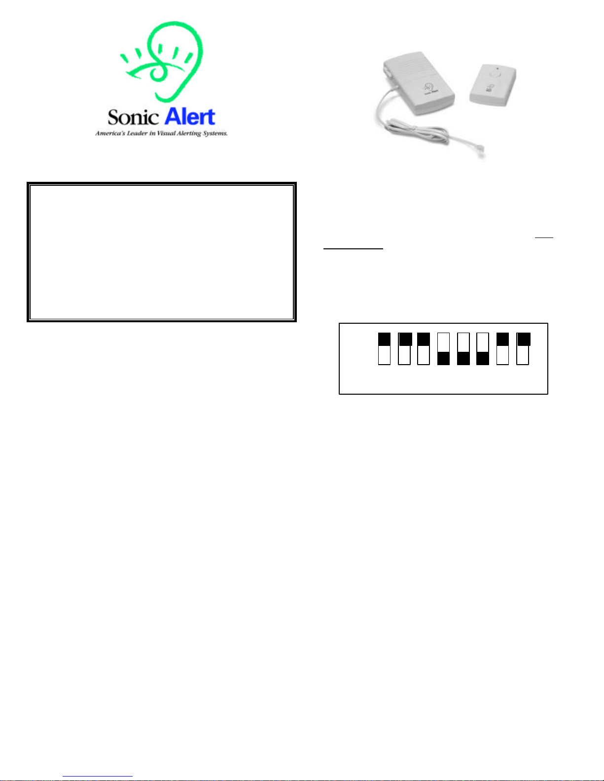
Setting The Dip Switches:
DB Sensor settings (smaller unit) dip switches 1 thru 6 are set at
the factory and only need to be changed if your neighbor has a
DB200 or DB100. The 8 dip switches should be set as follows:
a) 1 thru 3 dip switches are set in the ON position and 4 thru 6
are set in the OFF position. If you need to change the dip switch
settings to avoid interference with your neighbors make sure you
change both the DB200 Signaler to match the DB Sensor.
b) The 7th switch is for use when using 2 sensors; this switch
determines the settings for front or back door. If using for one
door only set this switch in the ON position. At this setting your
unit will flash at a fast rate and will make a ding/dong sound. If
using 2 sensors one for the front door and one for the back door
the setting for the 2nd sensor would be in the OFF position. In this
position the front door will flashat a different flash rate than the
back door. In the OFF position your back door sensor will flash
at a slow rate with a dong/dong sound.
c) The 8th switch determines the number of flashes when
someone is at your door. In the ON position your unit will flash 5
times and in the OFF position your unit will flash 10 times. This
feature is wonderful when you have an extra sensor for the back
door. One sensor would be set in the ON position and the other
would be set in the OFF position
Directions continuedon back
ON
OFF
1 2 3 4 5 6 7 8

Multi-Function-Input Jack:
Located on the left side of the DB Sensor, this input jack is for
installations as shown below in diagram 2 & 5. .
Setting The Speaker Switch:
Top -OFF
Bottom -ON
Located on the DB200 Signaler, larger of the 2 units:
The speaker switch allows you to turn the Audio Alarm ON or
OFF. ON is down and OFF is up
DB200 INSTALLATION DIAGRAMS
Battery free
installation: Use wire
Provided, plug into
jack outlet on side of
Transmitter. Remove
chime cover and
connect the red and
white wires to chime
box terminal screws
common and front.
Setting The Function Switch:
Top position -Intercom/Buzzer System/ Wireless Chime
box Installation see (3&4).
Center -Doorbell Button only see
diagram 1 & 2.
Bottom -Hard Wired to Existing
Doorbell Chime Box Installation see (5).
The function switch on the back of DB sensor (smaller unit)
should be set depending on which installation application you
need. See diagram on back.
Telephone Signaler Installation:
See figure 4 for telephone ringer cord installation. It
is necessary to use a 2 to 1 telephone adapter (can
be purchased at Radio Shack or hardware stores) if
plugging in a telephone or tty in same modular outlet.
Troubleshooting & Help:
If you’ve followed the directions and are still having problems please try the
following suggestions:
1) Check battery in the sensor must be a 9-volt alkaline type.
2) Check dip switch settings both the sensor and the signaler must match as
shown in figure 1.1 above.
3) Check outlet for power.
4) Move the Signaler to an outlet closer to the sensor unit.
5) If using the Multi-Function input jack make sure that the wires are not
touching each other. See diagram number 2 & 5 for proper installation.
6) Check Function setting switch for proper position.
7) Check that sensor is not further than 40 feet from the receiver.
8) For intercom installation, its important to line up the speaker icon on back of
sensor located just above the battery cover to the right of the small screw. This
must be centered over the speaker of the intercom. Check function switch must be
set in the top position (Intercom/Buzzer System).
9) For Technical help call 1-248-577-5400, M-F 7:30 a.m.-6:00 p.m. Eastern
time. Or e-mail us with your questions at
sonic-[email protected]
Warranty:
Thank you for purchasing this high quality Sonic Alert product. We hope you
will have many years of satisfied use. This Sonic Alert product comes with a
limited 5-year warranty so please retain your receipt in safe place for possible
future reference; you will need in the event of warranty service.
Sonic Alert, Inc.
1050 East Maple Rd.
Troy, MI 48083
V/TTY 1-248-577-5400 fax 248-577-5433
Web Site: www.SonicAlert.com
See all our product offerings at:
www.SonicAlert.com
Or call for a free catalogue 1-248-577-5400 V/TTY
REV 1.3
Table of contents
Other Sonic Alert Telephone Accessories manuals


