IBA ibaRackline-PC CAM User manual

ibaRackline-PC CAM/HD
iba Industrial Computer
Manual
Issue 1.1

Manufacturer
iba AG
Königswarterstr. 44
90762 Fürth
Germany
Contacts
Main office +49 911 97282-0
Fax +49 911 97282-33
Support +49 911 97282-14
Engineering +49 911 97282-13
E-Mail: iba@iba-ag.com
Web: www.iba-ag.com
This manual must not be circulated or copied, or its contents utilized and disseminated,
without our express written permission. Any breach or infringement of this provision will
result in liability for damages.
©iba AG 2020, All Rights Reserved
The content of this publication has been checked for compliance with the described
hardware and software. Nevertheless, deviations cannot be excluded completely so
that the full compliance is not guaranteed. However, the information in this publication
is updated regularly. Required corrections are contained in the following regulations or
can be downloaded on the Internet.
The current version is available for download on our web site http://www.iba-ag.com.
Windows® is a label and registered trademark of the Microsoft Corporation. Other
product and company names mentioned in this manual can be labels or registered
trademarks of the corresponding owners.
Certification
The device is certified according to the European standards and directives. This device
corresponds to the general safety and health requirements. Further international cus-
tomary standards and directives have been observed.
This equipment has been tested and found to comply with the limits for a Class A digital device, pursuant to part 15 of
the FCC Rules. These limits are designed to provide reasonable protection against harmful interference when the
equipment is operated in a commercial environment. This equipment generates, uses, and can radiate radio frequency
energy and, if not installed and used in accordance with the instruction manual may cause harmful interference to radio
communications. Operation of this equipment in residential area is likely to cause harmfulinterference in which case the
user will be required to correct the interference at his own expense.
Issue
Date
Revision
Chapter
Author
Version HW /
FW
V 1.1
08/05/2020
New motherboard

ibaRackline-PC CAM/HD Manual
Issue 1.1 3
Table of contents
1About this manual...........................................................................................5
1.1 Targ et group.................................................................................................. 5
1.2 Designations ................................................................................................. 5
1.3 Symbols used................................................................................................ 6
2Scope of delivery.............................................................................................7
3Versions ...........................................................................................................8
3.1 Factory setting............................................................................................... 8
4Safety instructions ..........................................................................................9
4.1 Designated use ............................................................................................. 9
4.2 Proper installation site ................................................................................... 9
5Description ....................................................................................................10
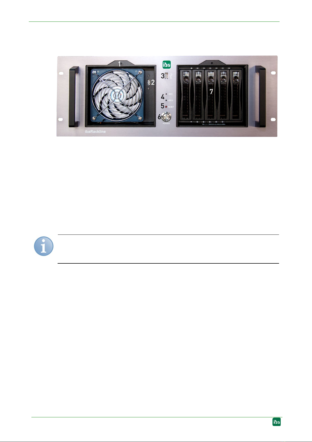
5.1 Front view ................................................................................................... 10
5.2 Rear view .................................................................................................... 11
5.3 Internal view ................................................................................................ 12
5.4 Error monitoring .......................................................................................... 13
5.4.1 ibaOut-Tem p................................................................................................ 13
5.4.2 ibaOut-State................................................................................................ 14
5.5 Default installation position for cards ........................................................... 15
6Installation, connection and first switching on ..........................................16
6.1 Safety instructions....................................................................................... 16
6.2 lnstallation ................................................................................................... 16
6.3 Connection and first switching on ................................................................ 16
7Installation of measuring or additional boards ..........................................17
7.1 Safety instructions and notes ...................................................................... 17
7.2 Basic procedure .......................................................................................... 17
7.3 Opening the device ..................................................................................... 18
7.4 Installing ibaOut-Temp/ibaOut-State............................................................ 19
8Maintenance work .........................................................................................23
8.1 Basic procedure .......................................................................................... 23
8.2 Cleaning or replacing the dust filter ............................................................. 23
8.3 Cleaning and replacing the fan.................................................................... 24
8.4 Replacing the power supply unit.................................................................. 24
8.4.1 Power supply slide-in module for replacement of
redundant power supply unit........................................................................ 25
8.4.2 Replacing the complete redundant power supply unit.................................. 25
8.5 Restoring of a RAID system during operation.............................................. 28
8.5.1 System with Onboard RAID......................................................................... 28
8.5.2 System with RAID controller plugged in....................................................... 30
9Installing operating system and iba software.............................................35
9.1 Installation................................................................................................... 35
9.2 Installing Windows with the Recovery medium ............................................ 35
9.2.1 General ....................................................................................................... 35

Manual ibaRackline-PC CAM/HD
4 Issue 1.1
9.2.2 Select the language .................................................................................... 36
9.2.3 Enter the product key .................................................................................. 36
9.2.4 Partitioning.................................................................................................. 37
9.2.5 Completing installation ................................................................................ 39
9.3 Windows Updates ....................................................................................... 39
9.4 Antivirus Software ....................................................................................... 39
9.5 Installing iba software.................................................................................. 39
10 Technical data ............................................................................................... 40
10.1 Main data .................................................................................................... 40
10.2 Electronic components and interfaces......................................................... 40
10.3 Products...................................................................................................... 41
10.4 Device dimensions ...................................................................................... 42
11 Support and contact ..................................................................................... 43

ibaRackline-PC CAM/HD Manual
Issue 1.1 5
1 About this manual
This manual describes operation of the industrial PCs ibaRackline-PC CAM and
ibaRackline-PC HD.
1.1 Target group
This manual addresses in particular the qualified professionals who are familiar with han-
dling electrical and electronic modules as well as communication and measurement tech-
nology. A person is regarded to as professional if he/she is capable of assessing safety
and recognizing possible consequences and risks on the basis of his/her specialist train-
ing, knowledge and experience and knowledge of the standard regulations.
1.2 Designations
The following designations are used in this manual:
Action Designations
Menu command Menu Logic diagram
Call of menu command Step 1 – Step 2 – Step 3 – Step x
Example:
Select menu „Logic diagram – Add –
New logic
diagram
Keys <Key name>
Example: <Alt>; <F1>
Press keys simultaneously <Key name> + <Key name>
Example:
<Alt> + <Ctrl>
Buttons <Button name>
Example:
<OK>; <Cancel>
File names, Paths „File name“, „Path”
Example:
„Test.doc“

Manual ibaRackline-PC CAM/HD
6 Issue 1.1
1.3 Symbols used
If safety instructions or other information are used in this manual, they mean:
The non
-observance of this
safety information may result in an imminent risk of death or
severe injury:
-
By an electric shock!
-
Due to the improper handling of iba software products which are coupled to input and
output procedures with control function!
If you do not observe the safety instructions regarding the process and the system or
machine to be controlled, there is a risk of death or severe injury!
The non
-
observance of this safety information may result in a potential risk of death or
severe injury!
The
non-observance of this safety information may result in a potential risk of injury or
material damage!
Note
An information indicates special requirements or actions to be observed.
Important Note
Information that a special indication has to be observed, e.g. exceptions from the general
rule.
Tip
Tip or example which serves as helpful information or a trick to facilitate the work.
Other documentation
Reference to supplementary documentation or further literature.

ibaRackline-PC CAM/HD Manual
Issue 1.1 7
2 Scope of delivery
After unpacking check the completeness and intactness of the delivery.
The scope of delivery includes:
Industrial computer ibaRackline-PC CAM or ibaRackline-PC HD
Keyboard
Mouse
Mains cable
Documentation (on DVD)
External DVD drive
The documentation contains:
Manual (pdf)
Third party documentation (pdf)
Windows 10 Enterprise Long-Term-Servicing Version or Windows Server Version
Recovery medium (for the respective Windows version and all associated operating
system settings)
iba software, optional order
Hardware driver (motherboard, graphics card)
1 iba software license key (dongle), optional with iba software product and installed
inside of the device on request of the client
Serial number (iba-S/N)

Manual ibaRackline-PC CAM/HD
8 Issue 1.1
3 Versions
ibaRackline-PC CAM: RAID 5 system with 5 3,5“ SAS hard disks, 1 redundant
power supply unit, 1 RAID controller, external DVD drive
ibaRackline-PC HD: RAID 5 system with 5 3,5“ SAS hard disks, 1 NVMe-SSD, 1 re-
dundant power supply unit, 1 RAID controller, external DVD drive
Upgrade options:
Server system with Windows Server 2016 or higher
Hard disc extension from 5x 4 TB to 5x 8 TB SAS or to 5x 12 TB SAS
Additional graphics card
3.1 Factory setting
In delivery state, 2 users with or without password are configured:
User Password
pda -
Administrator xadmin
Important note
Change the default passwords after you have put the PC into operation!
This way, unau-
thorized usage will be impeded.

ibaRackline-PC CAM/HD Manual
Issue 1.1 9
4 Safety instructions
4.1 Designated use
The device may be used only for the following applications:
Machine test and commissioning of industrial systems
Measurement data logging and analysis
Applications of iba software products (ibaPDA, ibaLogic etc.)
4.2 Proper installation site
The device can be installed only according to manufacturer's specifications:
19“ cabinet
19“ rack line
Electric Shock!
Before opening the device disconnect it from the mains and pull out the mains plug from
t
he socket equipped with earth contact!
Never use the device with a damaged mains cable!
Before opening the device disconnect it from the mains by unplugging the
mains
cable
from the
socket equipped with an earth
contact and wait for several minutes until the
components have cooled down!
This will prevent injuries
due to the electric shock or
burns!
Connect the device to one supply voltage only according to specifications on the built-
in power supply unit!
Always use
a socket equipped with earth
contact! Use a terminal strip with overvoltage
protection or an uninterruptible power supply (UPS)!
Always connect the device to earthed power networks (TN
-
networks according to VDE
0100 Part 300 and IEC 60364
-
3)! The operation via ungrounded networks or networks
(IT networks) earthed via impedance is not permitted!
In case of faults, a defective device or a possible defect pull out the mains plug from the
socket equi
pped with earth contact!
Never put a damaged device into operation!
Pay attention to sharp edges in the housing!
Never switch off the device by means of the mains switch
before you have shu
t down
the
device.
Electrostatic discharge!
Touch the components only in electrostatically discharged state!

Manual ibaRackline-PC CAM/HD
10 Issue 1.1
5 Description
5.1 Front view
(Image without cover panels)
1 Fan, can be replaced from the front
2 USB interface for hidden dongle mounting
3 USB interface
4 LEDs (hard disk indicators)
5 Reset button
6 Power button
7 Plug-in slots for hard disks
Note
On delivery of the device the iba
s
oftware license key is in the documentation or on
client's request plugged
-in in the device.
Display elements
The display consists of 2 LEDs:
LED 1: HDD1 (hard disk 1)
LED 2: HDD2 (hard disk 2)
The hard disk controller is connected to the LED 1 and lights up green in case of hard
disk activity.

ibaRackline-PC CAM/HD Manual
Issue 1.1 11
5.2 Rear view
1 2x Power supply with switch and plug for non-heating appliances, replaceable
2 Slots X20 to X26 (iba-cards for rackline slot)
3 Connections for external devices (keyboard, mouse, network etc.)
4 Slot for controller
5 Free slots X3 to X7 (PCIe), X8 (PCI)

Manual ibaRackline-PC CAM/HD
12 Issue 1.1
5.3 Internal view
1 PCI Express slots
2 Controller
3 Slots for iba-cards for rackline slot
4 Power supply unit (for RAID systems redundant)
5 Drive frame
6 Fan ( Ø 12 cm), mounting angle for redundant power supply unit
7 Additional fan (as option)
8 Hold-down clamp

ibaRackline-PC CAM/HD Manual
Issue 1.1 13
5.4 Error monitoring
ibaOut-Temp card installed illustrated by ibaRackline-PC
The temperature and the status of the power supply unit can be monitored with the slot
cards ibaOut-Temp and ibaOut-State. The cards can be ordered separately. If one of the
cards is ordered with a PC, it is installed by default in slot X20. If you want to install the
card later on, refer to chapter 7.4.
The status of temperature and power supply unit are indicated each with a bicolored LED
on the cards.
LED Status Description
TEMP green
red
Temperature OK
Overtemperature
POWER green
red
Power supply OK
Power supply error
Redundant power supply: error in one of the two power
supply units
5.4.1 ibaOut-Temp
ibaOut-Temp provides two relay outputs for temperature and power supply (2-pin con-
nector), which can be used to indicate errors. Both error types are indicated separately.
The switch position of the outputs is as follows:
Status Switch POWER Switch TEMP
Power off or power error closed open
Power OK, temperature OK open open
Power OK, overtemperature open closed
Contact loading capacity
Nominal current: 400 mA
Nominal voltage: 60 V
Compatibility to previous models
ibaRackline computers of older series only provide one relay output for error indication.
The relay contact is closed when an error occurs, without differentiating between over-
temperature or a power supply error.

Manual ibaRackline-PC CAM/HD
14 Issue 1.1
ibaOut-Temp can be used in the same way, when both outputs are connected to one
output (parallel circuit).
Wiring diagram of the parallel circuit:
5.4.2 ibaOut-State
ibaOut-State provides an output (6-pin connector) which can be used to indicate errors.
Both error types are indicated separately.
These are the switch positions:
Switch state switch state
Power OK,
temperature OK
Power off or
Power error and
overtemperature
Power error,
temperature OK
Power OK,
overtemperature
Contact loading capacity
Nominal current: 300 mA
Nominal voltage: 220 V DC
Compatibility to previous models
The behavior of ibaOut-State is identical with the previous models with a relay output, if
pin 5 and 6 are used. The relay contact of the previous ibaRackline models is closed
when an error occurs, without differentiating between overtemperature or a power supply
error.

ibaRackline-PC CAM/HD Manual
Issue 1.1 15
5.5 Default installation position for cards
On delivery, the data acquisition cards and additional cards are installed by default in the
slots described below.
Backview ibaRackline-PC CAM/HD
Specfic slots for the mainboards
Slot X2: controller
Installation slots for data acquisition cards (X3 - X7)
The cards are installed starting with slot X7 to slot X3
(X7 corresponds to the first card, card no. 0)
Installation slots for cards with rackline slots (X20 - X26)
ibaOut-Temp or ibaOut-State is installed in slot X20
ibaFOB-4o-D rackline-slot is installed starting with X25 and connected to X7 down-
wards.
ibaFOB-4o-D rackline-slot as sync-out (mirroring output ) is installed in X26 and
connected to X7
Connections of ibaFOB-4o-D with ibaFOB-D input cards:
X25 - X7
X24 - X6
X23 - X5
X22 - X4
X21 - X3
Installation slots for additional network cards
Additional network cards are installed starting with slot X3
GigE cards are installed in the slots X4 and X6
A PCI card is installed in slot X8 (e.g. CP1616)

Manual ibaRackline-PC CAM/HD
16 Issue 1.1
6 Installation, connection and first switching on
6.1 Safety instructions
Electric Shock!
Never use the device with a damaged mains cable!
Connect the device to one supply voltage only according to specifications on the built-
in
power supply unit!
Always use a socket equipped with earthing contact! Use a terminal strip with overvolt-
age protection or an uninterruptible power supply (UPS)!
Connect the device only to earthed power networks (TN
-
networks according to
VDE
0100 Part 300 or IEC 60364-3)!
The operation via ungrounded networks or networks (IT networks) earthed via imped-
ance is not permitted!
Never put a damaged device into operation!
6.2 lnstallation
Note
If you install the device into a 19" cabinet with rotating rack, consider the depth of the
device. Observe the minimum bending radii of the cables.
1. Place the device from the front onto the 19" rack line.
2. Fasten the device using 4 screws at the 19" rack line.
3. Plug in the mains cable of the device into a socket.
6.3 Connection and first switching on
Note
Before switching on the device
for the first time check if the power supply is
properly
connected and the connecting cable (fiber optic and copper data cable) are plugged
in
.
The device is delivered
pre-installed and configured.
Refer to the relevant manuals or
online help for the settings of the operating system and the iba software
.
1. Connect all cables.
2. Switch on the device using the mains switch.
3. Boot the device. Press the power button.
The computer is booted automatically with Windows.
4. Finally, start all iba software applications.

ibaRackline-PC CAM/HD Manual
Issue 1.1 17
7 Installation of measuring or additional boards
7.1 Safety instructions and notes
Electric Shock!
Before opening shut down the device! After that disconnect it from the mains and pull
out the mains plug from the socket equipped with earthing contact!
Wait for several minutes after switching off until the components have cooled down!
Thus you will
avoid injuries due to the electric shock or burns!
Pay attention to sharp edges in the housing!
Electrostatic discharge!
Touch the components only in electrostatically discharged state!
Note
If you upgrade the device, observe the instructions in the
third party documentation.
Back up all data on an external storage medium.
7.2 Basic procedure
If you carry out any work at the device, always proceed in the following way:
1. Remove all mobile data carriers (DVD, memory cards and so on).
2. Shut down the device.
3. Switch off the device.
4. Unplug the mains cable from the socket.
5. Remove the cover.
6. Carry out upgrade operations.
7. Attach the cover again.
8. Put the device into operation again.

Manual ibaRackline-PC CAM/HD
18 Issue 1.1
7.3 Opening the device
1. Turn the screws located on the upper side of the cover a quarter of a turn counter-
clockwise.
2. Lift the housing cover.

ibaRackline-PC CAM/HD Manual
Issue 1.1 19
7.4 Installing ibaOut-Temp/ibaOut-State
The temperature and the status of the power supply unit can be monitored with the slot
cards ibaOut-Tem p and ibaOut-State, see also chapter 5.4.
The installation procedure is identical for both cards. The installation is described below
using the example of ibaOut-Temp in an ibaRackline system.
ibaOut-Temp
Order no. 11.110001
ibaOut-State
Order no. 11.110002
After having opened the housing cover proceed as follows:
1. ibaOut-Temp can be installed in one of the slots X20 to X26 (X20 is recommended).
2. Break out the cover plate of the intended slot on the back of the device using a screw-
driver.
3. Above the slot, there is a screw in an opening, which is used to fix the card later.
Loosen the screw and remove it.

Manual ibaRackline-PC CAM/HD
20 Issue 1.1
Electrostatic discharge!
Touch the compon
ents only in electrostatically discharged state! Hold the card cautious
ly at
the
edges and at the slot bracket.
4. Insert the card in the respective slot. The bar at the bottom is used to fix the card.
5. Fasten the card with the previously loosened screw.
6. Connect the cables as follows:
This manual suits for next models
1
Table of contents
Other IBA Desktop manuals